Table of Contents
Advertisement
Advertisement
Chapters
Table of Contents

Related Manuals for GSE 250


Summary of Contents for GSE 250
- Page 1 GSE Model 250 Digital Indicator Series Technical Reference Manual Issue AC...
- Page 3 Information in this Technical Reference Manual is subject to change without notice due to correction or enhancement. The information described in this manual is solely the property of GSE. This manual may not be distributed without written permission of GSE. GSE Locations...
-
Page 5: Table Of Contents
Selections and Options ____________________________________________________________ 23 Numeric Entry __________________________________________________________________ 23 Keypad ________________________________________________________________________ 23 Update Model 250 Firmware _________________________________________________________ 26 Chapter 4: Setup ______________________________________________________ 27 Accessing the Setup Mode __________________________________________________________ 27 Full Setup ______________________________________________________________________ 27 ... - Page 6 Physical Seal _____________________________________________________________________ 46 Chapter 7: Setpoints ___________________________________________________ 49 Setpoint Connection _______________________________________________________________ 49 Setpoint Operation (250 and 250SS) __________________________________________________ 49 Checkweigh Operation (250X) ________________________________________________________ 49 Chapter 8: Communications _____________________________________________ 50 Automatic Weight Output ___________________________________________________________ 51 ...
- Page 7 Master Serial Output _______________________________________________________________ 53 Advanced Communication __________________________________________________________ 53 Using GSE View Software ________________________________________________________ 53 Protocol Summary _______________________________________________________________ 54 Example: Reading a Weight or Setpoint Value ________________________________________ 55 Example: Remote Keypress _______________________________________________________ 57 Example: Reading a Value in Hexadecimal ___________________________________________ 58 ...
- Page 8 This page is intentionally left blank Page 8 250 Technical Reference...
-
Page 9: Chapter 1: Introduction
Standard Model 250 The ABS plastic version of the Model 250 is available in wall/desktop and can be panel mounted. It may be operated from either 4 AA batteries or a DC power source from 12V to 24V. -
Page 10: Manual Set
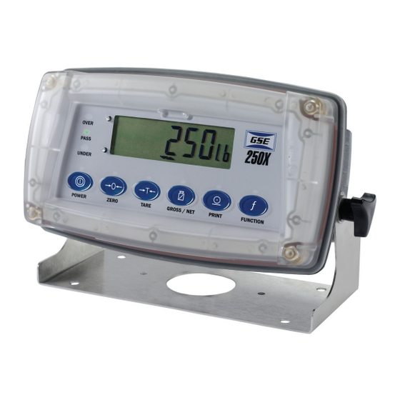
The Model 250X enclosure is rated as IP69K for severe washdown applications. The Model 250X may be operated from 9.6V, 12V or 24V batteries or a DC power source from 12V to 24V. This version of the Model 250 is only available in wall/desktop. Figure 3: Model 250X Indicator •... -
Page 11: Specifications
Keypad 6 key silicon rubber 6 key membrane 6-key capacitive GSE Link Infra-red connector for optional GSE-Link PC cable (to RS-232 PC port) RS-232 RS-232 automatic transmit, network or printer outputs. Communication Transmission rate: 2400, 4800, or 9600 baud 2 isolated transistor drive... - Page 12 This page is intentionally left blank Page 12 250 Technical Reference...
-
Page 13: Chapter 2: Installation
• Make sure all AC powered equipment is installed near an easily accessible power socket outlet. • To avoid the possibility of electric shock or damage to the Model 250, always switch OFF or isolate the indicator from the power supply before maintenance is carried out. -
Page 14: Cable Connections
To install wires in the Model 250 and Model 250SS, depress the lever located beside the terminal required and push wire into the hole. Release the lever and pull gently on the wire to ensure it is secure in the terminal. -
Page 15: Load Cell Connection
For more information, refer to SCALE (Scale Base Test Display) page 36. The Model 250 will accept either 4-wire or 6-wire load cell cable connection. To correspond with the actual cabling installation the indicator must be configured in setup to the correct setting. For more information, refer to CABLE (4-Wire or 6-Wire) page 30. -
Page 16: Communication Port Connection
RS-232 S ERIAL Connection between the indicator and computer DB9 or DB25 serial port (RXD, TXD, GND) DB9 RS-232 - Indicator to PC (250/250SS) DB9 RS-232 - Indicator to PC (250X) DB25 RS-232 - Indicator to PC (250X) DB25 RS-232 - Indicator to PC (250/250SS) -
Page 17: Printer Connection
SPEC:REM.FN parameter must be set. Refer to page 34 for configuration details. NOTE: The remote input will not function when in setup or when using the Opto-Link. Remote Key Input Connection (250/250SS) Remote Key Input Connection (250X) WARNING Do not connect voltage to the remote key input switch or connection terminals. -
Page 18: Setpoint Output Connection
250SS ODEL The output drivers for the Model 250 are isolated open emitter transistor drives that are capable of driving up to a total of 300mA. This configuration allows for the direct connection of the indicator outputs to most PLC types. -
Page 19: Gse-Link Option Connection (Opto-Link)
Model 250 display. To facilitate a quick and simple connection, the infrared transceiver is secured in place by a permanent magnet located within the head of the GSE-LINK. -
Page 20: Connecting Shields
The ground lug of the indicator must be separately connected to ground potential via a reliable link. The Model 250 should only be connected to ground via a single reliable link to avoid ground loops. Where each indicator is separately grounded, interconnecting cable shields should be connected at one end only. -
Page 21: Chapter 3: Configuration
The units display shows the units of the weight reading as either grams (g), kilograms (kg), pounds (lb), tons (t), none ( ) or ounces (o) (250X only). If the Model 250 is set up for counting, the units display will show pieces (p). -
Page 22: Status Annunciators
ETUP NNUNCIATORS When in Setup Mode, the Model 250 displays editing annunciators. Figure 7 identifies each of the editing annunciators. While in the Setup Mode, press the corresponding key below the annunciator. Figure 7: Editing Annunciators (Setup Mode) -
Page 23: Selections And Options
EYPAD All Models of the 250 utilize the same six keys in the same configuration. The material used for each model keypad is different however. Each key performs a different function in the weigh mode and setup mode. - Page 24 30 for more information. POWER Key The [POWER] key is used to turn the Model 250 on and off. To initially turn the indicator on, press and hold the [POWER] key. The display will show the following: Display segments will light and then clear.
- Page 25 [TARE] key. GSE-LINK Activation This feature is used to temporarily connect a PC to the Model 250 for calibration and setup purposes. A long press of the [GROSS/NET] key from the weigh mode will toggle the GSE-LINK infrared communications On/Off.
-
Page 26: Update Model 250 Firmware
Refer to the WD.LOC parameter on page 34 for details on setup and use. The Model 250 has flash memory on the main board. It is possible to update the firmware simply by using a computer. The firmware is loaded into a flash memory IC via the RS-232 port or GSE- Link. -
Page 27: Chapter 4: Setup
Full Setup. Refer to FULL.PC (Full Security Access code for Digital Setup) page To access the Full Setup mode, first ensure the indicator is on. • For the 250 and 250SS press and hold both the [POWER] and [f ] keys together for two seconds. -
Page 28: Setup Display Prompts
(allowing the user to enter the correct access code). To save settings, exit setup, and return to the normal weighing mode use one of the following methods. The Model 250 and 250SS can use any of the three examples. The Model 250X only allows Method 3. -
Page 29: Groups And Items
All keypad setup options in the Model 250 are organized in a tree structure made up of Groups and Items. To simplify this manual, Groups and Items will be notated as follows (GROUP:ITEM). Refer to Setup Menu Quick Reference page 69 for a list of all Groups and Items. -
Page 30: Res (Count-By Resolution)
Default: INDUST FILTER (Reading Average) The Model 250 can average a number of consecutive readings when calculating the displayed weight. This is used to reduce unwanted weight fluctuations caused by vibrations or dynamic forces. High settings will stabilize the display at the expense of rapid response to sudden weight changes. -
Page 31: Cal
Default: 0.5-1.0 (0.5 graduations per second) INIT.Z (Initial-Zero on Startup) This function can be used to automatically ZERO the indicator during power-up. The amount of weight that can be zeroed is limited to +/- 10% of full scale. Options are: ON or OFF Default: OFF Z.TRAC (Zero Tracking Sensitivity) Zero tracking allows the display to adjust for minor changes in the zero balance of the scale. -
Page 32: Spec
Select to enter the mV/V value of the full scale capacity of the scale build. This feature enables the Model 250 to be calibrated based on the rated output capacity of the load cells rather than using test weights. The accuracy of this method is limited to the accuracy of the published load cell ratings. -
Page 33: Full.pc (Full Security Passcode For Digital Setup)
AUT.OFF (Auto Power Off / Battery Operation) The Model 250 can be set up to automatically power down after a period of no activity. Weight motion, network communications or any press of the keypad is enough to keep the indicator powered up. -
Page 34: Serial
Options are: PWR: Never powered off battery 4.8 (250 & 250SS only), 9.6 (250X only),12, 24 (Battery Voltage) Default: PWR WD.LOC (Washdown Front Panel Key Locking) (250X only) This feature locks the keypad during washdown. Enable this feature and save the change. Turn the Model 250X off. -
Page 35: Set.pts Or Checkw
-, D: DTR handshake disabled or enabled Default: n81-. (For most applications the default setting is applicable.) ADDRES (Indicator Address) Use this option to set the Model 250 address when operating with network communications. Range 01 to 31 Default: 31 RST.CON (Reset Printed Consecutive Number) -
Page 36: Clock
MINUTE (Set Minute) Range: 00 to 59 Items within this Group allow access to the testing routines for the Model 250. With these routines the scale base output can be monitored and the inputs and outputs can be tested. SCALE (Scale Base Test Display) Verifies the correct load cell capacity and/or load cell wiring is used. -
Page 37: Factory
The parameter can be used for exiting the setup mode. Refer to page 28 for details. The Model 250 has a special function key on the front panel. The function of this key can be configured to any of the key functions detailed below. -
Page 38: Units
5. Press the [LIVE WT] key to force the sample to be re-calculated. 6. Once the weight is returned to the zero 'dead' band, the cycle can be repeated. Page 38 250 Technical Reference... -
Page 39: Show Total (Accumulation)
OTAL CCUMULATION The SHOW.T function is used for product accumulation. The function key will be labeled [TOTAL]. The [PRINT] key is used not only to print the current weight but also to add that weight to the current total. Press the [TOTAL] key to display count followed by the number of items in the total. Performing an Accumulation If the total weight is too large to display in six digits, the weight is shown in two sections labeled with the upper six digits displayed before the lower six digits. - Page 40 This page is intentionally left blank Page 40 250 Technical Reference...
-
Page 41: Chapter 5: Calibration
Chapter 5: Calibration The calibration results are stored in permanent memory for use each time the Model 250 is powered up. Note: Some of the parameters in the setup mode can affect calibration. The BUILD and OPTION settings MUST be configured before calibration is attempted. -
Page 42: Zero
<SEL>, <EDT> or <OK> to re-edit the calibration weight and repeat the operation. In applications where test weights are not easily available, it is possible to calibrate the Model 250 directly by entering the mV/V readings at Zero and full scale Span. -
Page 43: Dir.spn (Direct Span Calibration Entry)
DIR.SPN (D IRECT ALIBRATION NTRY Press the <OK> key to start. The display will show the current weight. Press the <OK> key to enter the Direct Span setting. Change the mV/V setting to the correct full scale value using the <SEL> and <EDT> keys. Press the <OK>... -
Page 44: Clr.lin (Clear Linearization)
To reset the calibration to factory condition, access the CAL parameter. Refer to FAC.CAL (Restore Default Factory Calibration) page 32. The menu choice will only be available when the Full Setup mode is accessed. Page 44 250 Technical Reference... -
Page 45: Chapter 6: Approvals
Chapter 6: Approvals The Model 250 may be operated in Industrial, OIML or NTEP mode. (Note: For NSC requirements, use the OIML setting.) The industrial mode operates without an reference to trade regulations. The OIML and NTEP modes restrict certain aspects of indicator operation to ensure compliance with the respective trade certified standards. -
Page 46: Oiml Requirements
The calibration mode is enabled or disabled by pushing a button marked “setup” located on the rear of the indicator. To seal the Model 250, the R.ENTRY parameter must be set to “ON”. Refer to page 31 for more details. Follow the steps below to access and set the R.ENTRY parameter and place the lead seal. - Page 47 10. Place the physical seal plastic cover over the load cell and comm port connectors, and then install the drill head screw. 11. Thread the wire security seal through the indentations in the plastic cover and the drill head screw. Figure 8: Model 250 and Model 250SS Panel Mount Physical Seal Version 2.4 Page 47...
- Page 48 Figure 9: Model 250X Physical Seal Page 48 250 Technical Reference...
-
Page 49: Chapter 7: Setpoints
Chapter 7: Setpoints The Model 250 is capable of working with two internal setpoints. The status of these setpoints is displayed on the LCD. Each setpoint is associated with a physical output driver which allows control of an external light or buzzer. - Page 50 This page is intentionally left blank Page 50 250 Technical Reference...
-
Page 51: Chapter 8: Communications
The Model 250 offers one bi-directional RS-232 communication port or an optional fiberoptic link (GSE-Link) for seamless communication. This provides a number of serial output options allowing communications with external devices such as printers, computers, PLCs or remote displays. For wiring connections and pinouts, refer to Communication Port Connection page 16. -
Page 52: Printing
The Model 250 comes standard with a single fixed printing format that is as follows: 000048 12/05/2006 15:10 121.4 lb G 5.3 lb T 116.1 lb N The first line contains a six digit sequential ID number that is automatically incremented with each printing, up to a maximum of 999999. -
Page 53: Master Serial Output
(RS-232 or GSE-link) and then set the protocol. If a GSE Link is being used, be sure to press and hold the [GROSS/NET] button on the Model 250 until all annunciators are flashing. -
Page 54: Protocol Summary
The Model 250 indicator contains a number of registers. The indicator is configured by reading and writing the information stored in these registers. Information such as gross weight is obtained by reading the register. The Model 250 has registers of different types to hold weights, menu options, etc. -
Page 55: Example: Reading A Weight Or Setpoint Value
Codes for Read Literal Value Registers Register Description Code Example Version of the protocol 0001 V1.0 Copyright message 0002 © GSE 2006 Model of indicator 0003 Software version 0004 V1.20 Indicator serial number 0005 3123456 Contents of LCD display memory... - Page 56 Network address 0143 0000001F Reset printer sequence command 0144 Full date/time string 0150 10/16/2005 10:32 Date format selection 0151 00000000 Date 0152 00000011 Month 0153 0000000A Year 0154 000007D3 Hour 0155 0000000A Minute 0156 00000020 Page 56 250 Technical Reference...
-
Page 57: Example: Remote Keypress
This example shows how to perform a keypress remotely. It is possible to simulate keypad keypress via RS-232 or GSE-link. Refer to the chart below for the hexadecimal code for each key. The entered value is always preceded with 20 and is followed with the code for the type of transaction and then the register of the stored data. -
Page 58: Example: Reading A Value In Hexadecimal
20 and is followed with the code for the type of transaction and then the register of the stored data. Enter 20110026: Then enter one of the following commands: Command Program Send GSE View <Alt> 013 <Alt> 010 Communication Plus <CR><LF> Other terminal program Page 58 250 Technical Reference... - Page 59 In decimal, this value is 295. Register Description Code Example Version of the protocol 0001 V1.0 Copyright message 0002 © GSE 2006 Model of indicator 0003 Software version 0004 V1.20 Indicator serial number 0005 3123456 Contents of LCD display memory...
- Page 60 Special function setting 0161 00000000 Auto power off setting 0162 00000000 Backlight options 0163 00000000 Remote key function setting 0164 00000000 Setpoint target high 0171 000007D0 Setpoint target low 0172 000003E8 Counting sample quantity 0180 0000000A Page 60 250 Technical Reference...
-
Page 61: Example: Setting A Value
For example, set the Target High value to 500 lb. Make sure the units are configured for lb at the BUILD:UNITS parameter. Enter 20120171:1F4 (1F4 in hexadecimal = 500 decimal) Then enter one of the following commands: Command Program Send GSE View <Alt> 013 <Alt> 010 Communication Plus <CR><LF> Other terminal program 0171 Read Literal... -
Page 62: Error Codes (Registers)
Cannot modify register values while SETUP menus are active REG_ERR_RESERVED_4 0010H Reserved for future use REG_ERR_RESERVED_3 0008H Reserved for future use REG_ERR_RESERVED_2 0004H Reserved for future use REG_ERR_RESERVED_1 0002H Reserved for future use REG_ERR_DATA_ERROR 0001H Internal data error Page 62 250 Technical Reference... -
Page 63: Chapter 9: Troubleshooting
(DENIED) information. More than three attempts have been made to access the setup mode with the incorrect access Turn the Model 250 off. When the indicator is code. turned back on, enter the correct access code to access setup. Entered linearization point must be between zero (LIN.PT) -
Page 64: Diagnostic Errors
Remove all weight from scale. Scale wiring (HIGH) +2mV/V. incorrect. IAGNOSTIC RRORS The Model 250 will display specific codes for faults or out of tolerance conditions. These errors will be displayed as an E type error message. Error Description Solution Message (E0001) The power supply voltage is too low. -
Page 65: Appendix
Appendix Model 250 (Plastic Enclosure) Panel Mount Version Dimensions shown in mm 3D View Front View Side View Back View Version 2.4 Page 65... - Page 66 Model 250 (Plastic Enclosure) Desk Mount with Battery Compartment Version Dimensions shown in mm 3D View Front View Side View Back View Page 66 250 Technical Reference...
- Page 67 Model 250 (Stainless Steel Enclosure) Panel Mount Version Dimensions shown in mm Version 2.4 Page 67...
- Page 68 Model 250X IP69K version Dimensions shown in mm Wall Mount Indicator with Swivel Bracket 3D View Front View Side View Bottom View Page 68 250 Technical Reference...
-
Page 69: Setup Menu Quick Reference
Note: ⊗ Full Setup only. Changing this setting will increment the Calibration Counter. Full Setup only. Changing this setting will not increment the Calibration Counter. Group (GRP) Item (ITM) Page ⊗ DP (Decimal Point Position) ⊗ CAP (Maximum Capacity) ⊗ RES (Count-by Resolution) BUILD ⊗... - Page 70 This page is intentionally left blank Page 70 250 Technical Reference...
-
Page 71: Index
NDEX NTEP, 47 OIML, 47 CAP, 21, 62 Capacity, 21 4-Wire Connection, 7 Cleaning, 5 CLOCK, 28, 62 CLR.LIN, 24, 36, 62 Connecting shields, 12 6-Wire Connection, 7 Consecutive number reset, 27 Count, 29 Count by resolution, 22, 62 Access codes, 19 full setup, 25 safe setup, 24 Accessing the setup mode, 19... - Page 72 Gross/net Master serial output, 45 GSE-link activation, 17 MINUTE, 28, 62 Gross/net key, 15, 17 MONTH, 28, 62 gse view communication, 45 MOTION, 14, 22, 62 Group, 21 Motion detection, 14, 22 Groups and items, 21 GRP, 21 GSE view software, 45...
- Page 73 S.in P, 24 Tare Safe setup access code, 19, 24 legal for trade, 37 SAFE.PC, 24, 62 Tare key, 16 Scale setup mode, 15 setting capacity, 15 weigh mode, 15 SCALE, 28, 62 TARG.HI, 62 Scale base test display, 28, 62 TARG.LO, 62 Scale Build, 23 Target...
-
Page 75: Version
Model 250 Series Technical Reference Manual Version 2.4 Part Number: 39-10-42438...
Need help?
Do you have a question about the 250 and is the answer not in the manual?
Questions and answers