
Subscribe to Our Youtube Channel
Related Manuals for GSE 350


Summary of Contents for GSE 350
- Page 1 Model 350/355 Digital Weight Indicator User Instructions AWT35-500349 Issue AA June 2009...
- Page 2 © Avery Weigh-Tronix group of companies 2009. All rights reserved. No part of this publication may be reproduced, stored in an electronic retrieval system, or transmitted in any form or by any means, electronic, mechanical, photocopying, recording or otherwise without the prior written consent of the copyright owner, or as permitted by law or under license.
-
Page 3: Table Of Contents
2.2.1 LED ................................ 8 2.2.2 LCD ................................ 8 .............................. 9 EMOTE ISPLAY OPERATION .............................. 10 350) ........................ 10 NTERING A ARE ALUE ODEL 355) ........................ 10 NTERING A ARE ALUE ODEL ............................. 10 NTER AN ... - Page 4 3.9.4 Discharge Example ........................... 20 3.10 ............................ 21 ILL AND ISCHARGE 3.10.1 Enter a Target ............................ 21 3.10.2 Pre‐acts .............................. 21 3.10.3 Activation Method .......................... 22 3.10.4 Pause .............................. 22 3.10.5 Fill and Discharge Example ........................ 22 3.11 ............................ 23 BSOLUTE ...
-
Page 5: Installation
Installation The standard Model 350 zinc die cast enclosure is a NEMA1 (IP 20) equivalent. The Model 350/355 stainless steel enclosure meets NEMA 4X/IP65 type specifications. WARNING: Risk of electrical shock! Service of the indicator should only be performed by authorized service personnel. -
Page 6: Outline Drawings
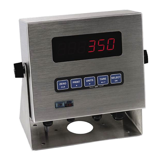
Outline Drawings 1.3.1 350 Die Cast Figure 1: Model 350 Die Cast Dimensions 1.3.2 350 Stainless Steel Figure 2: Model 350 Stainless Steel Dimensions AWT35‐500349 | June 2009 Page 4 ... -
Page 7: 355 Stainless Steel
1.4.1.1 ON/OFF Switch The on/off switch for the Model 350 die cast is a rocker-type switch that is located on the rear of the enclosure. The on/off switch for the Model 350/355 stainless is a toggle-type (washdown type) switch replaces one of the available strain reliefs on the bottom or rear of the enclosure. -
Page 8: Keypad And Display
2.1.1 Model 350 Keypad The Model 350 offers a sealed 5-button elastomer keypad which is used for operator input. Each key is assigned two distinct functions. Various key combinations are also used. Each key has secondary functions; allowing an operator to enter target values, perform piece samples, access setup parameters, etc. -
Page 9: Model 355 Keypad
2.1.2 Model 355 Keypad The Model 355 keypad performs different functions in the Weigh Mode and the Count Mode. The numeric keys make entering values such as tare or average piece weight easier. TARGET ZERO PRINT SELECT TARE START UNITS SAMPLE STOP ENTER... -
Page 10: Weigh Mode Functions
2.2 Displays The Model 350 is available with a LED or LCD while the Model 355 is only available with a LED. The Model 350 and Model 355 will display alphanumeric data, but due to the nature of 7-segment LEDs/LCD and the limitation of six digits, some information is abbreviated. -
Page 11: 2.3 Remote Display
The remote display function allows a master indicator (Model 350 or Model 355) to be echoed to another indicator (350 Series or 60 Series) and be used in a remote location. There are certain parameters that must be set in order to have the master and slave indicators communicate together. If the remote display mode is enabled, r-dsp will be shown on the display. -
Page 12: Operation
Operation The Model 350 and 355 can operate in a variety of modes such as check-weighing, parts counting and filling etc. The functions described in this section are not available until enabled within the setup parameters. Contact your GSE distributor to configure the indicator for a specific operation. -
Page 13: Set Time & Date
The time and date can be accessed from the weigh mode with the key if the time/date parameter has been enabled. Time and date can be accessed via the communication port by sending 11%s. 3.4.1 Model 350 To enter the date from the Enter~date~01.01.70 prompt EXAMPLE: 01.09.09 (January 9, 2009) 1. Press to toggle through the numbers to enter the month. -
Page 14: Parts Counting
A new sample must be performed for each unique part being counted. The indicator will not store the average piece weight. 3.5.1 Model 350 3.5.1.1 Sample selectable fixed counts from the weigh mode 1. From the weigh mode, press until the QTY annunciator is lit. -
Page 15: Model 355
3.5.2 Model 355 3.5.2.1 To sample using selectable fixed counts from the weigh mode 1. From the weigh mode press Add 10 will be displayed. If 10 is the desired sample size, go to step 3. Otherwise go to step 2. 2. -
Page 16: Percentage Checkweigh
(if counting is enabled). 3.6.1 Enter a Target Value 3.6.1.1 Model 350 1. Press until tArG1 is displayed. If the target value shown is correct, press to go to the PctLo value. -
Page 17: Start Checkweighing
3.7.1 Enter a Target Value Pressing alone allows access to the subsets. PA1 and PA2 are the subsets for Targ 1. 3.7.1.1 Model 350 1. Press until tArG1 is displayed. 2. Press until the first digit of the new target is displayed. Press to accept the number displayed. -
Page 18: Start Fill
If no value is to be entered or PA1 is not displayed, press to go to the next screen. 4. If PA2 is displayed, enter the value in the same manner as the target weight was entered above and press to accept or press to return to the weigh mode. -
Page 19: Batch
3.8.1 Enter a Target Pressing alone allows access to the subsets. PA 1 and PA 2 are the subsets for Targ 1. 3.8.1.1 Model 350 1. Press until tArG1 is displayed. 2. Press until the first digit of the new target is displayed. Press to accept the number displayed. -
Page 20: Start Batch
3.8.2 Start Batch 3.8.2.1 Activation Method The batch begins with the selected activation method. The method is determined by the parameters in the setup mode. The deactivation of the setpoints is automatic. The desired target may be based on net or quantity (if counting is enabled). -
Page 21: Discharge
(PA1 – PA3). This feature must be enabled before attempting to use. 3.9.1 Enter a Target 3.9.1.1 Model 350 1. Press until tArG1 is displayed. 2. Press until the first digit of the new target is displayed. Press to accept the number displayed. -
Page 22: Pre-Acts
3.9.2 Pre-acts Pre-act 1 is used for dual-speed dispensing. Pre-act 1 specifies when the system should switch from fast- discharge to slow-discharge. When using a single-speed device, pre-act 1 should be set to 0 from the Setup Mode. Pre-act 2 specifies the point where the final cutoff should occur, regardless of a single-speed or dual- speed operation. -
Page 23: Fill And Discharge
(PA1 and PA2). This feature must be enabled before attempting to use. 3.10.1 Enter a Target 3.10.1.1 Model 350 1. Press until tArG1 is displayed. 2. Press until the first digit of the new target is displayed. Press to accept the number displayed. -
Page 24: Activation Method
3.10.4 Pause The 350/355 can pause setpoint operations. This is useful as a safety device, for mid-cycle operator breaks, mechanical adjustments, etc. This feature must be enabled before attempting to use. When invoked, Pause deactivates all setpoints. The display will show: Tare= ~ Abort. Pressing will abort the current cycle;... -
Page 25: Absolute Checkweigh
This feature must be enabled before attempting to use. 3.11.1 Enter a Target Value 3.11.1.1 Model 350 1. Press until tArGL is displayed. The low target value will need to be entered. Go to step 2. 2. Press until the first digit of the new target is displayed. -
Page 26: Absolute Checkweighing Example
This feature must be enabled before attempting to use. 3.12.1 Enter a Target Value 3.12.1.1 Model 350 1. Press until tArG1 is displayed. The target value will need to be entered. Go to step 2. 2. Press until the first digit of the new target is displayed. Press to accept the number displayed. -
Page 27: Start Checkweighing
3. Press Once the tare key is pressed, Lo will be displayed. This is where the lower tolerance value will be entered. Enter this value in the same manner as the target weight was entered above. If the displayed value is correct, press 4. -
Page 28: Batch 2
“No Targ” will be displayed. This feature must be enabled before attempting to use. 3.13.1 Enter a Target 3.13.1.1 Model 350 1. Press until tArG1 is displayed. 2. Press until the first digit of the new target is displayed. Press to accept the number displayed. -
Page 29: Batch2 Example
3.13.2.1 Annunciators Status Annunciator Status Annunciator Color (LED) Relay 1 Contacts Closed, Fill 1 SP 1 Illuminated Relay 2 and 3 Contacts Open Relay 2 Contacts Closed, Fill 2 SP 2 Illuminated Relay 1 and 3 Contacts Open Relay 3 Contacts Closed, Fill 3 SP 3 Illuminated Relay 1 and 2 Contacts Open... -
Page 30: Troubleshooting
Troubleshooting The Model 350/355 utilizes the following types of error messages: Operational Errors, Hardware Errors, Calibration Errors, Communication Errors, and Miscellaneous Errors. Operational Errors Under Load. Input signal is less than negative full scale. Check load cell wiring. Code02 Code03 Over load input signal is greater than positive full scale. -
Page 31: 4.3 Hardware Errors
4.3 Hardware Errors An EPROM problem detected during power up. Code00 A-D ~ Bad! Problem with A/D chip detected. Disconnect any options installed and re-power the unit. Options are connected to the same serial lines as the A/D so they may prevent Or Code17 it from working properly. -
Page 32: Specifications
Input (J3): 12 – 36VDC, minimum 0.8A w/no options or 1.25A w/options installed (internal power supply version) Excitation Voltage 10 VDC Excitation Current 180 mA max. / (6) 350Ω bridge F.S. Signal Input 0.1 mV/V min – 20 mV/V max Signal Connection 4 lead or 6 lead with sense... - Page 33 Enables the communication port to be a digital 20 mA current loop port. Fiber Optic Transceiver Model 350/355 stainless steel, installs in the safe area and connects to a Model 350/355. Allows setpoints and/or analog output options. Communicates with hazardous area indicator via fiber-optic cable.
- Page 34 Avery Weigh-Tronix USA 1000 Armstrong Dr. Fairmont MN 56031 USA Tel:507-238-4461 Fax:507-238-4195 Email: usinfo@awtxglobal.com www.wtxweb.com Avery Weigh-Tronix UK Foundry Lane, Smethwick, West Midlands, England B66 2LP Tel:+44 (0) 8453 66 77 88 Fax: +44 (0)121 224 8183 Email: info@awtxglobal.com www.averyweigh-tronix.com...
Need help?
Do you have a question about the 350 and is the answer not in the manual?
Questions and answers