
Related Manuals for GSE 350


Summary of Contents for GSE 350
- Page 1 GSE Model 350/355 IGITAL EIGH NDICATOR Technical Reference Manual Flash Version...
- Page 3 Model 350/355 Technical Reference Manual Flash Version...
- Page 4 Information in this Technical Manual is subject to change without notice due to correction or enhancement. The information described in this manual is solely the property of GSE. No part of this manual may be reproduced or transmitted in any form or by any means, electronic or mechanical, including photocopying and recording and sold for any monetary figure without the express written permission of GSE.
-
Page 5: Table Of Contents
............................ 4 EYPAD 355 K ............................ 6 EYPAD Weigh Mode Functions ....................... 7 Entering a Tare Value (Model 350).................... 8 Entering a Tare Value (Model 355).................... 8 CHAPTER 2: INDICATOR INSTALLATION................9 ............................9 OUNTING Desktop Mounting........................9 Panel Mounting (Die Cast Only) ....................9 Permanent Mounting ........................ - Page 6 RANSFORMER Specifications ..........................39 Transformers Available ......................39 IEC line cords Available......................39 ........................ 40 IBER PTIC NTERFACE CHAPTER 4: CONFIGURATION....................43 350) ................... 43 NTERING THE ETUP ODEL 355) ................... 44 NTERING THE ETUP ODEL ......................44 ELECTING A ARAMETER ....................
- Page 7 Activation Methods (General)....................70 Pre-acts (General) ........................71 Learn Feature (General)......................71 Pause Feature (General) ......................71 Changing Targets from the Weigh Mode (General) ..............72 Example (General)........................72 Bargraph (General) ........................73 ....................75 ERCENTAGE HECK EIGHING Setpoint Activation (ChecP)...................... 75 Changing Targets from the Weigh Mode (Percentage Check-Weighing) ........
- Page 8 Example (Batch2)........................93 ........................ 93 ETPOINT RROR ODES ........................94 EMOTE ETUP ......................94 EMOTE ERIAL PERATION Display Capture Utility......................95 350).................... 96 IME AND ETUP ODEL 355).................... 97 IME AND ETUP ODEL RS-485 M ............. 98 ULTI ETWORK ETUP AND PERATION Setup............................
- Page 9 NTEP P ..................123 ANEL OUNT EQUIREMENTS OMIL R ......................... 124 EQUIREMENTS ........................ 124 THER EQUIREMENTS ....................... 125 EALING AND UDIT RAILS Physical Seal........................... 125 Audit Trails ..........................126 CHAPTER 7: TROUBLESHOOTING ..................129 ........................129 RROR ESSAGES Operational Errors ......................... 129 Setup Mode Errors........................
-
Page 11: Chapter 1: Introduction
HAPTER NTRODUCTION Thank you for selecting the GSE Model 350/355 Indicator. The Model 350 and Model 355 continue the GSE tradition of Excellence in Weighing and Counting Technology. A properly installed and maintained Model 350 or Model 355 will provide many years of reliable, accurate performance. - Page 12 Input (J3): 10 – 36VDC, minimum 0.8A w/no options or 1.25A w/options installed (internal power supply version) Excitation Voltage 10 VDC Excitation Current 180 mA max. / (6) 350Ω bridge F.S. Signal Input 0.1 mV/V min – 20 mV/V max Signal Connection 4 lead or 6 lead with sense...
-
Page 13: Display
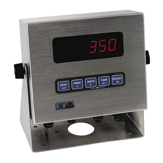
The Model 350 and Model 355 indicators are available with either a six digit, 7-segment green LED display, a six digit, 7-segment black LCD display or a 7-segment backlit LCD display. The Model 350 and Model 355 will display alphanumeric data, but due to the nature of 7-segment LEDs/LCD and the limitation of six digits, some information is abbreviated. -
Page 14: Lcd Display
Illuminates when the battery reaches a low tolerance. LCD only 350 Keypad The Model 350 offers a sealed 5-button elastomer keypad is used for operator input. Each key is assigned two distinct functions. Various key combinations are also used. Each key has secondary functions; allowing an operator to enter target values, perform piece samples, access setup parameters, etc. - Page 15 The Model 350 keypad performs different functions in the Weigh Mode, the Setup Mode, and the Calibration Mode. Secondary functions for each key allow you to perform additional tasks. Key Press Weigh Mode Count Mode Setup Mode Performs a gross zero function and/or clears an entry in progress.
-
Page 16: 355 Keypad
Chapter 1 355 Keypad The Model 355 keypad performs different functions in the Weigh Mode, the Setup Mode, and the Calibration Mode. The number keys make entering a tare value or average piece weight easier. TARGET ZERO PRINT SELECT TARE START UNITS SAMPLE... -
Page 17: Weigh Mode Functions
EIGH UNCTIONS The Model 350 and Model 355 keypads have five primary Weigh Mode functions: Performs a gross zero and selects the gross mode Initiates data transmission out the communication port Toggles the units of measure between lb, kg, g, lb oz, oz... -
Page 18: Entering A Tare Value (Model 350)
Chapter 1 350) NTERING A ALUE ODEL If a tare value is known, it is possible to enter that value into the tare register. Follow the steps below. P167 must be enabled to use this feature. From the gross or net mode press the key until tare is displayed. -
Page 19: Chapter 2: Indicator Installation
The standard Model 350 zinc die cast enclosure is a NEMA1 (IP 20) equivalent. The Model 350/355 stainless steel enclosure meets NEMA 4X type specifications. When choosing a mounting location for the Model 350 die cast, ensure that the unit is not installed in a washdown area or conductive dust environment. -
Page 20: Permanent Mounting
The optional mounting bracket allows the zinc die cast enclosure to be securely fastened to another surface. The bracket is attached to the indicator with two thumbscrews and can be swiveled to an optimal viewing angle. Figure 5: Model 350 Zinc Die Cast with Optional Mounting Bracket UTLINE RAWINGS... - Page 21 350/355 Technical Reference Figure 7: Model 350 Stainless Steel Dimensions Figure 8: Model 355 Stainless Steel Dimensions...
-
Page 22: Wiring
A description of all wiring terminals is included on the bottom label of the zinc die cast enclosure as shown in Figure 11. Figure 11: Model 350 Zinc Die Cast Enclosure Wiring Label ONNECTIONS A high quality braided shield cable with 16 to 24 AWG stranded wire is recommended for load cell or summing box connections. -
Page 23: Serial Port Connections
Excitation) must be connected together with (- Sense) on the Model 350 die cast. Sense jumpers are standard on the Model 350/355 Stainless Steel (E3 and E4). Utilizing the (+) and (-) Sense leads of six conductor cables provides compensation for variations in the excitation voltage due to resistance changes in the cable. -
Page 24: Remote Key Connection
EMOTE ONNECTION A remote key may be connected to the Model 350/355 communication port to provide remote activation of print, tare, or zero functions. The connection for the remote key input is between pin 1 and pin 6 of the DB9 communication port connector (see Figure 15 for die cast, Figure 14 for stainless). -
Page 25: Remote Display Connections
OUNT RANSFORMER An external wall mount transformer is supplied with the die cast Model 350 for connection to 120VAC, 60Hz power and is plugged into J4 of the 350 die cast main board. Do not cut the ground prong off the wall mount transformer! To connect the transformer: 1. - Page 26 OWER UPPLY The Model 350 die cast may be powered by an external 12-36 VDC or 12-26 VAC power source. The power supply should have a minimum current rating of 800mA with no options installed, a minimum current rating of 1.25A with options installed. Recommended plugs are AMP MTA .156” or MOLEX .156”.
-
Page 27: Chapter 3: Option Installation
350/355 Technical Reference Chapter 3: Option Installation The capabilities of the Model 350 can be expanded with the use of one or more option kits. This chapter provides installation procedures for these options. Model 350/355 Options The following options are available for the Model 350: •... -
Page 28: Panel Mount Kit
The Panel Mount Kit provides an easy way to mount the indicator into new or existing cabinetry. See Figure 21 for detailed instructions on panel mounting the Model 350 die cast. See also NTEP Panel Mount Requirements on page 123 for additional panel mounting NTEP requirements. -
Page 29: Analog Card Connections
High voltages may exist within the enclosure! To prevent the risk of electrical shock, ALWAYS unplug the Model 350/355 when opening the enclosure. Installation and servicing of the Model 350/355 should be performed by authorized and qualified service personnel only. - Page 30 Be sure to avoid ‘pinching’ the cable between the housing halves. Affix all appropriate labels to the back of the indicator. To install the Analog Output Module without mounting bracket (Model 350/355 Stainless): If only one option is being installed in a fiber-optic hub indicator use the following instructions. If two options are being installed along with a fiber-optic option an option mounting plate is required.
- Page 31 7. Reinstall the back cover. Tighten the eight screws securely to create a good seal. Be sure to avoid ‘pinching’ the cable between the housing halves. To install the Analog Output Model with Option Mounting Bracket (Model 350/355 Stainless): 1. Open the indicator.
-
Page 32: Analog Connections
Provides an isolated ground connection. Iout Used for 4-20 or 0-20 mA analog signal output. 350 D Place this label on the rear of the indicator above the analog option knockout. Wire the option connector in accordance with the label (left to right). -
Page 33: Analog Board Diagnostic And Test Procedures
350/355 Technical Reference 350/355 S TAINLESS TEEL Cut off the text “ANALOG OUTPUTS” from the label and place it on the connector shown below (apply to the area just under the field external wire terminals). NALOG OARD IAGNOSTIC AND ROCEDURES The following test procedures affect the analog output signal levels. - Page 34 Chapter 3 To test the 0-20mA output mode: Voltmeter readings are based on the use of a 500 ohm precision resistor. Caution! Do not exceed 500 ohms. 1. Enter the Setup Mode (see Setup Mode on page 43). Chngs Poss! P110.-- ~ F.S.= ~ 100.00 2.
- Page 35 350/355 Technical Reference 5. Key in (see Setup Mode on page 43). Test ~ 4-20A Per P176 6. Press to set the output to 0%. 4-20A ~ 0P 7. Press to increase the output to 25%. 4-20A ~ 25P 8. Press to increase the output to 50%.
-
Page 36: Setpoint Card Connections
Setpoint Card Connections Using one of the software setpoint configurations (see General Setpoint Setup on page 70) in conjunction with the setpoint option board gives the Model 350/355 the ability to directly control external devices such as valves, relays, actuators, etc. - Page 37 2. Locate the three studs and one thru-hole on the main board that the option mounting bracket will be attached to. See Figure 27. Remove the nuts from the three studs on the main board. It may help to position the option mounting bracket over the 350 main board to locate the three studs and one thru-hole.
-
Page 38: Setpoint Connections
Chapter 3 3. Install the nylon stand-off supplied with the option bracket kit into the thru-hole on the option bracket. See Figure 27. The thru-hole is located on the option bracket, towards the center of the board, on the irregular flanged section (a smaller hole than the others on the bracket) that would be positioned towards the power supply regulator (U11) with a flanged heat sink on it. -
Page 39: Setpoint Board Diagnostic And Test Procedures
350/355 Technical Reference 350 D Place this label above the setpoint card knockout. 350/355 S TAINLESS TEEL Cut off the text “SETPOINT OUTPUTS” from the label and place it on the connector shown in Figure 23 (apply to the area just under the field external wire terminals). -
Page 40: Rs-485 Networking
High voltages may exist within the enclosure! To prevent the risk of electrical shock, ALWAYS unplug the Model 350/355 when opening the enclosure. Installation and servicing of the Model 350/355 should be performed by authorized and qualified service personnel only. -
Page 41: Network Connections
The new label will redefine all of the other pin designations. On the die cast enclosure, apply the label marked Model 350 STD to the outside of the enclosure. The supplied label RS485 COMM should completely cover the RS232 COMM portion of the factory installed label. - Page 42 Chapter 3...
-
Page 43: Bi-Directional
350/355 Technical Reference 20 mA Current Loop Option The 20mA option will convert the communication port of the indicator from RS-232 to 20 mA current loop. This is a digital communication signal and should not be confused with a 4 to 20-mA (or 0-20 mA) which is an analog output signal. -
Page 44: Max Voltage
The field connections to the 20 mA circuitry will be made at the main board’s comm connector, i.e. the lever connector on the Model 350/355 Stainless Steel version and at the ‘D’ connector on the Model 350 Zinc Die Cast unit. -
Page 45: Battery Power Supply
The Battery Module gives the Model 350/355 portability, providing an Model 350/355 with an LCD display and one loadcell 20 hours minimum battery life, or an Model 350/355 with an LED display and one loadcell 8 hours minimum battery life. -
Page 46: Connection
Chapter 3 Figure 31: Battery Option Installation (350 die cast) ONNECTION See Figure 32 for main board battery connections (J3). DESCRIPTION Positive terminal (VDC signal input) Negative terminal (VDC signal input) Low battery indicator terminal (TTL output - +5V OK, 0V Lo Bat) Shutdown NOTE: Earlier die cast model’s main board may have only 2 or 3 pins... -
Page 47: On/Off Switch
ON/OFF S WITCH The on/off switch for the Model 350 die cast is a rocker-type switch that mounts in the center rectangular hole punch-out. The on/off switch for the Model 350/355 stainless is a toggle-type (washdown type) switch that replaces one of the available enclosure strain reliefs. The switch is soldered to the board (die cast) or on a cable (stainless). -
Page 48: Temperature Sensing
ISPLAY NDICATION A Model 350/355 with LED display will flash “LoBat” on the display as a warning when the battery is low. A Model 350/355 with LCD display will turn on the square indicator between the MOTION and GROSS indicators on the bottom of the display. LOBAT is written above the indicator on the LCD lens. -
Page 49: International Transformer - Iec
All of the other features listed above will function with this version. International Transformer - IEC The Model 350 zinc die cast transformer (GSE P/N 20-20-35190) allows the 350 to run on overseas current. Mounting tabs and line cords provide installation flexibility, allowing easy mounting to walls, tables, shelves, etc. -
Page 50: Fiber-Optic Interface
Model 350 or 355 indicator. A fiber-optic communication kit (24350B-420B0) is necessary for connecting the hazardous area and safe area indicator. The fiber-optic communication kit provides all hardware necessary to link the hazardous and safe area indicators. Refer to the Model 350/355 I.S. manual for hazardous indicator installation instructions. - Page 51 350/355 Technical Reference 7. Terminate plastic fiber conductors by using snap-on connectors (GSE p/n 26-20-4531) and polishing kit (GSE p/n 31-80-0225) according to termination instructions (GSE p/n 39-10-42119). 8. Plug fiber connectors into connectors on fiber-optic board. Make sure that RX goes to TX and TX goes to 9.
- Page 52 HCS fiber-optic cable is not easily fabricated on site and tooling is too expensive for on time use. Prefabricated cables in 100 feet increments can be purchased from GSE. The cable comes ready to install with connecting ends and a strain relief for the enclosure.
-
Page 53: Chapter 4: Configuration
Setup ~ Enter Code 2. Press DISPLAY READS No ~ Chgs P110.— — ~ F.S.= ~ 100 When exiting the Setup Mode, the Model 350/355 prompts whether to enter the Calibration Mode. The display will then prompt to save any changes. -
Page 54: Entering The Setup Mode (Model 355)
P111.09 ~ 1Grad ~ 0.01 2. Press DISPLAY READS P112.05 ~ Ztrac ~ 0.5 d 3. Continue pressing to advance through all setup parameters. To access the previous parameter (Model 350): 1. Press DISPLAY READS 2. Press DISPLAY READS P111.09 ~ 1Grad ~ 0.01... - Page 55 When accessing a parameter, the parameter number appears briefly. The display then toggles between the parameter name and selection. Pressing will again briefly display the parameter number. To access a specific parameter (for example P200) (Model 350): 1. Press four times to select the first digit. DISPLAY READS 2.
-
Page 56: Changing A Parameter Value
P 110.-- Indicates Parameter Parameter Number Denotes “Key In” To enter a Key-In Parameter (350): 1. Press . A decimal point is used to represent the entry position. 2. Press until the desired character appears. -
Page 57: Saving Parameters
To enter a Key-In Parameter (355): 1. Key in the number by using the numeric keys. 2. Press to accept the entry. To setup a full scale value of 250 lbs (350): 1. Access the setup mode. DISPLAY READS P110.— — ~ F.S.= ~ 100 2. - Page 58 DISPLAY READS Enter ~ =End 4. Press to complete exit. DISPLAY READS 0.00 To exit the Setup Mode from the view-only mode (350): 1. Press to begin exiting Setup Mode. DISPLAY READS Enter ~ =End 2. Press to complete exit.
-
Page 59: Factory Default
DISPLAY READS 0.00 Factory Default Parameter 65001 and 65002 are available to return the Model 350/355 to factory settings. Parameter 65001 will reset parameters including the calibration, while parameter 65002 resets all parameters except the calibration. Return to factory default (350): 1. -
Page 60: List Of Parameters
List of Parameters The Model 350 and Model 355 have several parameters that can be configured to your specific application. Below is a table of the available parameters. Also refer to page 52 for explanations of each parameter. The parameters shaded in gray have been added to the flash version main board. - Page 61 Disable Network Option (Toggle) Disabled and 4 – 254 (Key P251.00 Addr Disable Network Address P260.00 350 (or 355) – Cntrl Type 350 or 355 Remote Display Type (4 Selection) P290.00 None – Port 2 Echo None Remote Display – Master Echo (3 Selections) P291.02...
-
Page 62: Parameter Map Details
Denotes the full scale capacity. This value should not exceed the rated capacity of the weighing device. P111 Division Size (Selection) Indicates the count-by and decimal point. Pressing (Model 350) or (Model 355) will automatically select the choice closest to 10,000 divisions without exceeding 10,000 divisions. P112 Zero Track Aperture (Selection) Set in terms of number of divisions. - Page 63 350/355 Technical Reference P115 Stability Delay (Selection) Selects the stability (motion) time delay to a resolution of 0.1 seconds. For example, an entry of 25 will be accepted as 2.5 seconds. P116 Filter (Selection) Sets the indicator response time in terms of seconds. Filtering determines how quickly the indicator will respond to changing input signals.
- Page 64 When P167 is on, the user can view tare using the select key (tare will follow Net). The unit will accept numeric tare. On the Model 355, users can use the numeric keypad. On the Model 350, users can use to scroll in an entry.
- Page 65 350/355 Technical Reference Choice Number Selection Name Description P210.00 All transmissions disabled. P210.01 Press Sends transmission with key. P210.02 Cont. Sends transmissions continuously. Send single transmission after weight is reached and motion ceases. P210.03 Cycle Must return display value below 0.1% of F.S. to reset for next transmission.
- Page 66 Set the style of indicator the display will be echoed to. Choose from 300 or 60. The 300 choice is for 350, 355, 350 I.S., 355 I.S., 351, ABS 4100. The 60 choice is for 460 series, 560 series and 660 series indicators.
- Page 67 350/355 Technical Reference P423 Back Light (on/off) Toggle the backlight on a 350/355 LCD P426 Low Battery Indication (Toggle) Press to enable or disable this option. Low battery will be indicated continuously if this feature is enabled without the battery option installed. Otherwise, an annnunciator will be lit when the battery voltage is low.
- Page 68 See Bargraph (General) on page 73. P5011 Setpoint Bargraph (Toggle) Enables or disables the bargraph display on the LCD version of the Model 350/355 display. This setup parameter only appears if an LCD display is installed. See Bargraph (General) on page 73.
-
Page 69: Preset Transmit Selections
350/355 Technical Reference Preset Transmit Selections The Model 350 and Model 355 provide 16 preset formats for printing tickets or sending data to a computer. Only one format or custom transmit may be enabled at a time. Choice 0 Custom Transmit: User-defined serial data string (see Custom Transmit Setup on page 60). - Page 70 Chapter 4 Choice 11: <STX><Unsigned Displayed Weight><SPS><CR> Choice 12: <STX><Unsigned DATA><sp><lb/kg><sp><Gross/Net/Qty><STAT><CR> Use choice 12 to send to a 450/455/550 remote display that is set to text mode and a <CR> terminator. Choice 13: <STX><Unsigned DATA><sp><lb/kg><sp><Gross/Net/Qty><STAT> <CR><LF> Choice 14 (Simulates NCI 3835): <LF>Signed DATA<CR><LF><STAT><CR><ETX>...
-
Page 71: Custom Transmit
350/355 Technical Reference Custom Transmit The serial output of the Model 350/355 can be configured for a custom application such as a remote display format, a customized computer program format, or a customized ticket format. The custom transmit must be designed in a computer-transmittable ASCII text file and is loaded into the indicator’s serial port via a... -
Page 72: Entering Ascii Text
Chapter 4 Access Setup and Clear Old Custom Transmit ASCII Text ASCII Control Codes Gross, Tare and Net Parameters Exit Setup and Save Changes Figure 37: Custom Transmit File ASCII T NTERING ASCII text is defined as printable characters, including alpha-numerics as well as punctuation and symbols. See Table 8 for a complete listing of ASCII characters. - Page 73 350/355 Technical Reference Table 6: ASCII / HEXADECIMAL CONVERSION CHART CHAR “ < > & ‘ ‘ Most printers require a carriage return (.013) and/or a line feed (.010) to print preceding data and avoid leaving data in the printer buffer. See Table 6 for a list of ASCII codes.
-
Page 74: Parameter Selection Numbers
Chapter 4 ARAMETER ELECTION UMBERS The following sequence enters parameters into a custom transmit: %e , the parameter number, %e%e , a format code, and then %e%e with no intervening spaces. %e 0 %e%e 0 %e%e Initiates Parameter Enters Parameter Format Enters Parameter... -
Page 75: Exiting Setup Mode And Saving Changes
350/355 Technical Reference Time/Date Format Codes Includes seconds with time. “10:07:40 am 01/26/01 24 hour time format. “10:08 01/26/01” “10:11 am Jan 26, 2001” Print date spelled out. “10:12 am Fri 01/26/01” Print day of the week. “10:12 am 26/01/01”... -
Page 76: Parts Counting
The counting parameter must be enabled at parameter 179 (P179) before the quantity mode is available. Refer to page 54 for details on the counting parameter and page 43 to enter the setup mode, make changes and save the change. To sample using selectable fixed counts (350): 1. From the Weigh Mode, Press to view the current net weight. -
Page 77: Analog Output Setup
8,000 lbs. 10 V (Max Output) Reset state – Specifies analog signal level when P176.01 AnRst 0 V (Min Output) Model 350 and Model 355 enters Setup Mode. No Change* 0 –10 volts*, P177.00 AType Specifies output type: voltage or current. -
Page 78: Analog Output Calibration
NTERING NALOG ALIBRATION ALUES An example of the printout included with each analog option kit follows below: 100%s23640%i%e Access Setup Modes, Allowing Changes 60100%s%e P60100. c1998-GSE- 60101%s%e P60101. 0350p01009 60102%s%e P60102. 06-30-2000 60200%s%e P60200. BrdSn573192 60201%s%e P60201. -
Page 79: Analog Output Example
Srl n 123456 Exit Setup Mode Analog calibration values can be entered into the Model 350/355 by keying in the data in the left-hand column, beginning at the line starting with “61200…”, replacing the “%s” character pairs with the and “%e” with the key. -
Page 80: Setpoint Setup
Remote or Auto. Check-weigh operations have no start function. Independent setpoint operations are limited to Above or Below activation. The Model 350 and Model 355 setpoint option board may be connected in- series with a larger automated control system or a manually activated switching device. A foot switch, a two- hand safety station, or other permissive-start devices may be used for safety or system compatibility. -
Page 81: Pre-Acts (General)
For instance, after repeated tests, a system consistently over-fills by .5 lbs. This is the value that should be entered as the pre-act. The 350/355 would then deactivate the setpoint .5 lbs. less than the desired final target value. -
Page 82: Changing Targets From The Weigh Mode (General)
(Model 355). A negative sign will be displayed. Press to continue with the entry Programs that involve a discharge cycle are loss-in-weight type applications. Any target or pre-act values for these programs should be entered as positive numbers. The 350/355 will automatically interpret these values as negative. XAMPLE ENERAL The target for the fill setpoint operation is Targ 1. -
Page 83: Bargraph (General)
350/355 Technical Reference To change targets from the Weigh Mode (355): 1. Press DISPLAY READS 0.00 2. Press to view the current fill target. DISPLAY READS Targ1 ~ 250 ARGRAPH ENERAL A bargraph display is available for the ChecP, Fill, Batch, Dschg, Both and ChecA setpoint modes of operation. - Page 84 Chapter 4 Bars ON Weight Range (Lower Tolerance Limit) < 10 10.00 to 15.00 15.00 to 20.00 20.00 to 25.00 25.00 to 30.00 30.00 to 35.00 35.00 to 40.00 40.00 to 45.00 45.00 to 50.00 Figure 39: Example #2 Bargraph Segments (Weighted Value) Figure 40: Examples of the Bargraph "Below, Within and Above Tolerance"...
-
Page 85: Percentage Check-Weighing
350/355 Technical Reference Percentage Check-Weighing This feature is commonly used in check-weigh applications. After a target weight is entered, upper and lower tolerances are entered as a percentage of the target. Over and under tolerance values are automatically calculated according to the percentages entered. The desired target may be based on gross weight, net weight or quantity (if counting is enabled). -
Page 86: Example (Checp)
Chapter 4 Example of how to change targets from the Weigh Mode: 1. Press to view the current net weight. DISPLAY READS 0.00 2. Press to view the current fill target. DISPLAY READS Targ1 ~ 250 3. Press to set a new fill target of 400 lbs. DISPLAY READS Targ1 ~ 400 4. -
Page 87: Fill
350/355 Technical Reference Fill The fill program is used for single-speed or dual-speed filling operations. The dual-speed fill operation allows for both a fast and a slow fill mode. During a fast-fill, setpoints 1 and 2 are activated. During a slow-fill or single-speed fill, only setpoint 1 is activated. -
Page 88: Learn Feature (Fill)
Chapter 4 EARN EATURE Pre-act 2 has a learn feature available which allows the indicator to adjust the final cutoff based on changing environmental conditions. See Learn Feature (General) on page 71 for ‘learn’ feature details. AUSE EATURE The standard pause feature (keypress, remote key closure or both) is available for the fill operation. See Pause Feature (General) on page 71 for ‘pause’... -
Page 89: Batch
350/355 Technical Reference Batch The standard batch program is used for batching up to three separate items. Ingredients 1 through 3 use setpoints and pre-acts 1 through 3 respectively. Ingredients are batched one at a time. Table 14: Setpoint Setup (Batch) -
Page 90: Pause Feature (Batch)
Chapter 4 AUSE EATURE ATCH The standard pause feature (keypress, remote key closure or both) is available for the batch operation. See Pause Feature (General) on page 71 for ‘pause’ details. HANGING ARGETS FROM THE EIGH ATCH When Batch is configured in the setpoint setup, Targ 1 automatically becomes an available mode for the key. -
Page 91: Discharge
350/355 Technical Reference Discharge The discharge program is designed for single-speed or dual-speed dispensing of product from a larger weigh vessel. Discharge is a loss-in-weight application similar in operation to the fill program. When a discharge is initiated, the scale automatically tares and comes to a net zero weight. The appropriate setpoints are activated and material is discharged until the decreasing net weight reaches the desired target value. -
Page 92: Learn Feature (Discharge)
Chapter 4 EARN EATURE ISCHARGE Pre-act 2 has the learn feature available which allows the indicator to automatically adjust the final cutoff based on changing environmental conditions. See Learn Feature (General) on page 71 for learn feature details. AUSE EATURE ISCHARGE The standard pause feature (keypress, remote key closure or both) is available for the discharge operation. -
Page 93: Both
350/355 Technical Reference Both The ‘Both’ program combines a fill operation with a discharge operation. This automates a single-speed vessel filling operation with a single-speed multiple dispensing function. Setpoint 1 is used for filling the vessel and Setpoint 2 is used for product discharge. The ‘both’ program uses values for two targets and two pre-acts. -
Page 94: Pause Feature (Both)
Chapter 4 AUSE EATURE The standard pause feature (keypress, remote key closure or both) is available for the Both operation. See Pause Feature (General) on page 71 for ‘pause’ functions details. ARGET HANGES FROM THE EIGH When Both is configured in the setpoint setup, Targ 1 and Targ 2 automatically become available modes for key. -
Page 95: Absolute Check-Weighing
In order for the annunciators or setpoints to activate, the displayed value must be at least five graduations above zero. A setpoint option board may be installed to allow the Model 350 to directly control lights, buzzers, drop-gates, or reject devices. -
Page 96: Example (Checa)
Chapter 4 2. Key in the desired target weight with no weight applied or add desired target weight to scale and press to set a new target weight. 3. Press to accept the target value. 4. Press to select the Lo target value. 5. -
Page 97: Independent Setpoint Operation
350/355 Technical Reference Independent Setpoint Operation Independent Setpoints allow controlling setpoints when the gross, net or quantity (if counting is enabled) is above or below a target value. The reset (deactivation) choice of each setpoint is selectable from Tare, Remote Key, Auto, Non-latching or Absolute. See Key-In Parameters on page 46 for instructions on using front panel keys for data entry. -
Page 98: Changing Targets From The Weigh Mode (Independent)
Chapter 4 Independent Setpoint Reset (deactivation) choices: Parameter Setting Reset Choice Description P51x5.0 Tare Setpoint deactivates with P51x5.1 Remote Key Setpoint deactivates with Remote Key closure. Setpoint deactivates when weight returns to +/- 5 graduations of zero and P51x5.2 Auto stabilizes. -
Page 99: Target Deviation Check-Weighing
Instead of keying in the target value from Targ 1, press [TARE] (350) or [ENTER] (355). Press [TARE] (350) or [ENTER] (355) again to accept the target. Lo and Hi are the subsets for Targ 1. Lo and Hi are entered as actual values. -
Page 100: Example (Checb)
Chapter 4 3. Press to access the low tolerance parameter. This parameter does not have to be changed. Go to step 4 to change the low tolerance or press to go to the weigh mode or press to view the high tolerance, go to step 6. - Page 101 350/355 Technical Reference Parameter Setting Acceptable Check-weigh Values Comments Target = 10.00 Desired container weight. Lo Value = 0.5 10.00 - 0.5 = 9.50 Low acceptable range = 9.50 to 10.00 Hi Value = 0.25 10.00 + 0.25 = 10.25...
-
Page 102: Batch 2
Chapter 4 Batch 2 The batch 2 program is used for batching up to three separate items without using preact values. Ingredients 1 through 3 use setpoints 1 through 3 respectively. Ingredients are batched one at a time. The target values can only be set from the weigh mode by pressing the [SELECT] key. -
Page 103: Example (Batch2)
350/355 Technical Reference XAMPLE ATCH With a system set up a system to make a 50,000 lb batch with water (30,000 lbs.), corn syrup (15,000 lbs.) and caramel color (5,000 lbs.), ingredient 1 should start with [TARE] and subsequent ingredients should auto-start. -
Page 104: Remote Key Setup
Chapter 4 Remote Key Setup The Model 350 and Model 355 have four selectable remote key operations to choose from: Print, Tare, Zero and Print/Tare. Only one of these operations may be assigned to the remote key input. Table 22 describes the available remote key operations. -
Page 105: Display Capture Utility
350/355 Technical Reference ISPLAY APTURE TILITY The Display Capture Utility sends the current display information out of the one of the available comm ports when the one of the two extended ASCII character represented by decimal 149 (hex: 95h) or decimal 150 (hex: 96h) are received through the comm port. -
Page 106: Time And Date Setup (Model 350)
Chapter 4 Time and Date Setup (Model 350) The time and date feature is stored as non-volatile (time/date setting will not be lost when the unit power is reset). The time/date parameter is available in the first two fixed transmits (See Transmit Selection on page 55) and can be included in a custom transmit (See Custom Transmit Setup on page 60). -
Page 107: Time And Date Setup (Model 355)
350/355 Technical Reference DISPLAY READS 4. Press to toggle through the numbers to enter the minutes. DISPLAY READS 16.3 5. Press once to move the cursor. Press to select the next digit. DISPLAY READS 16.32 6. Press twice to move the decimal point over to separate the minutes from the seconds. -
Page 108: Rs-485 Multi-Drop Network Setup And Operation
(i.e. networking). PERATION When P251 is enabled by choosing a valid address, the Model 350/355 will ignore all data it receives until an <STX> character is followed immediately by a character that matches the address defined by setup parameter P251. If these two conditions are met then the Model 350/355 will process all subsequent data until the end of block character, <ETX>, is received, signaling the end of the transmission. -
Page 109: Upgrade Indicator Firmware
Upgrade Indicator Firmware The Model 350 and Model 355 have flash memory on the main board where the parameters are stored. It is possible to update the firmware simply by using a computer. The firmware is loaded into a flash memory IC. -
Page 110: Remote Display Configuration
Remote Display Configuration The remote display function allows a master indicator (350 or 355) to be echoed to another indicator (350 Series or 60 Series) and be used in a remote location. There are certain parameters that must be set in order to have the master and slave indicators communicate together. -
Page 111: Setup Remote Indicator
350/355 Technical Reference • P292 - Transmit any ASCII character or control code to the remote indicator as an ending character after echoing unit’s display. Make sure this parameter matches P275 on the remote indicator. • P296 – Choose the remote indicator type, a 300 series or 60 series. - Page 112 Enables or disables the use of the keys on the master indicator (350). When this parameter is enabled and the keys are pressed, the Print and Units Enable* / P283.01...
- Page 113 350/355 Technical Reference Set P271 for Display and configure all other remote display parameters (refer to Table 27). Configure the parameters in the master indicator (refer to Setup Master Indicator on page 100). Make sure that the wiring connections between the master and remote indicators are correct (refer to on page 15.
-
Page 114: Control (Hazardous Area) To Hub (Safe Area) Configuration
Chapter 4 Table 28: Annunciator Choices ASCII Code Annunciator 1 Good2 Gross Other Annunciator 2 Spt 1 Spt 2 Spt 3 Motion The start character and end character can be any ASCII character 1 - 255. Refer to Table 28 for the annunciator codes to be entered in the custom transmit. -
Page 115: 300 Series Command Codes
350/355 Technical Reference Parameter Setting Control / Hub P280 Remote zero key – enabled P281 Remote units key – enabled P282 Remote select key – enabled P283 Remote ID key – enabled P284 Remote print key – enabled P285 Remote tare key – enabled P286 Remote enter key –... - Page 116 Remote Key 2 %’ Backward Select Clear Key (clears user input or can initiate an action Enter Key ID Key (Print & Units on 350) Turn off 350 Print Key/ Arrow Up Key Remote Key 1 Select Key Tare Key...
-
Page 117: Id Number Entry
350/355 Technical Reference ID Number Entry It is possible to enter an ID number and have it print out on a ticket. • P210 or P230 must be set to ID. • P213 or P233 must be set to cust. -
Page 119: Chapter 5: Calibration
DISPLAY READS First ~ Zero? ~ -0.26 Fast Calibration Fast Calibration allows calibration of the Model 350/355 scale system without accessing the Setup Mode. To access Fast Calibration from the Weigh Mode (350): 1. From the Weigh Mode, press DISPLAY READS Setup~Enter ~ Code! 2. -
Page 120: Performing Calibration
Establishing Zero The Model 350/355 provides five methods for obtaining a zero (no load) calibration reference, First Zero, Last Zero, False Zero, Only Zero, and Cal Reset. To select a calibration method (350): 1. - Page 121 350/355 Technical Reference 3. Remove any load on the scale. DISPLAY READS First ~ Zero? ~ -0.42 4. Press to establish zero. DISPLAY READS 0.00 5. Pause for motion delay. DISPLAY READS Enter ~ Load ~ 0.00 6. Place a 100lb test weight on scale.
-
Page 122: Last Zero
Establish gross zero before entering setup or calibration! Last Zero Calibration With Weight Already Applied Example (350): 1. Remove any load on the scale. DISPLAY READS 2. - Page 123 350/355 Technical Reference 6. Press DISPLAY READS Last ~ Zero? ~9930. 7. Press to use last zero. DISPLAY READS Enter ~ Load? ~ 9970. 8. Enter DISPLAY READS 10000 9. Press to establish span. DISPLAY READS 10000. 10. Pause for motion delay.
-
Page 124: False Zero
DISPLAY READS ALSE False Zero calibrates the Model 350/355 without removing the current gross weight. This is particularly useful in tank weighing applications where it may be both time consuming and costly to completely empty the tank. This operation is achieved by establishing a false (temporary zero) zero reference. - Page 125 350/355 Technical Reference DISPLAY READS Enter ~ Load? ~ 2510. 7. Enter DISPLAY READS 2500 8. Press to establish span. DISPLAY READS 2500. 9. Pause for motion delay. DISPLAY READS Cal ~ Good? ~ 2500. 10. Press to accept calibration.
-
Page 126: Only Zero
Only Zero is used to establish a new calibration zero without affecting the span. This is useful for correcting changes to the scale’s dead load, for example adding safety rails to a truck scale platform. Only Zero Calibration Example (350): 1. From the Weigh Mode, press... -
Page 127: Reset Calibration
After performing a calibration reset, a complete recalibration is required. The effects of a calibration reset do not take effect until the Model 350/355 recalibrated and calibration information has been saved. If Code 02 (under-load) or Code 03 (over-load) is displayed during calibration, press perform a calibration reset. - Page 128 Chapter 5 3. Remove any load on the scale. DISPLAY READS First ~ Zero? ~ xx.xx 4. Press to establish zero. DISPLAY READS Enter ~ Load? ~ 0.00 5. Place a 100lb test weight on scale. DISPLAY READS Code03 6. Press DISPLAY READS First ~ Zero? ~ -0.26 7.
- Page 129 350/355 Technical Reference DISPLAY READS Fast ~ Cal~First ~ Zero? ~ xx.xx 3. Remove any load on the scale. DISPLAY READS First ~ Zero? ~ xx.xx 4. Press to establish zero. DISPLAY READS Enter ~ Load? ~ 0.00 5. Place a 100lb test weight on scale.
-
Page 130: Multi-Point Linearization
Chapter 5 Multi-Point Linearization If the load cell signal input to the indicator has good repeatability and stability, then using multi-point linearization during calibration may significantly improve the ultimate accuracy of the data displayed by the indicator. Parameter 119 (P119) enables or disables this feature. Initially, the same basic procedures as a normal calibration are used to perform a multi-point linearization. -
Page 131: Examining Calibration Results
Establishing a Span Once a zero reference has been established, the Model 350/355 displays Enter ~ Load and awaits the entry of a span (test load) value. This value may be entered before or after the test load has been applied. -
Page 132: Exiting Calibration
Chapter 5 3. Press to establish span. DISPLAY READS 100.00 4. Pause for motion delay. DISPLAY READS Cal ~ Good? ~ 100.00 When making a significant change to the previous calibration, or when the calibration weight is less than 5% of full scale capacity, ReCal ~ ??? will be displayed instead of Cal ~ Good? In this event it is recommended that the calibration be performed a second time. -
Page 133: Chapter 6: Legal For Trade
In addition to all other NTEP requirements, the serial number of a panel mounted unit must be visible from the outside front of the controller. The serial number on the Model 350 rear label must be engraved in the space provided on the panel mount tag (see Figure 42). These serial numbers MUST match. The tag is designed to be applied to the top right edge of the enclosure or to the lower right of the front of the unit. -
Page 134: Omil Requirements
6. Re-install the electronics. Damage to the case or electronics is not covered by warranty. The NTEP panel mount requirements are applicable only to the Model 350 die cast model and panel mount kit. Figure 42: Panel Mount Unit - Serial Number Tag (Die Cast Model) -
Page 135: Sealing And Audit Trails
The Model 350/355 has two types of sealing provisions, a physical seal and a three event audit trail counter. Check with your local weights and measures authority to determine your requirements. -
Page 136: Audit Trails
UDIT RAILS Three separate incrementing, non-resetable audit trail parameters are used by the Model 350/355 to indicate changes to various parameters, P60201 – OIML, P60203 – Calibration , and P60204 – Setup. An audit trail counter will increment only once upon exiting the Setup Mode and saving changes regardless of how many settings were changed. - Page 137 Changes to any of the Setup Mode parameters will increment the setup audit trail at P60204. IEWING UDIT RAIL ARAMETERS Audit trail parameters may be viewed at any time. To view audit trail parameters: (Model 350) 1. Press DISPLAY READS Setup~Enter ~ Code! 2. Press DISPLAY READS -No- ~ Chgs!~P110 ~ FS ~ xx.xx...
- Page 138 Chapter 6...
-
Page 139: Chapter 7: Troubleshooting
This chapter contains error messages and information parameters, as well as information on setup parameter selections and A/D Calibration. Error Messages The Model 350/355 utilizes the following types of error messages: Operational Errors, Setup Mode Errors, Hardware Errors, Calibration Errors, Communication Errors, and Miscellaneous Errors. PERATIONAL RRORS Under Load. -
Page 140: Hardware Errors
Chapter 7 SPtxx ~ Error A conflict occurred with a setpoint value entry (example: target entry is less than preact). The digits ‘xx’ represent the last two digits of the setpoint parameter in error (example: SPt 5 ~ Error indicates a conflict P5105, preact 1). Prtcl ~ Error Existing protocol is invalid. -
Page 141: Miscellaneous Errors
(even with the internal program jumper in the “NO” position). Note that accessing the Setup Mode in this manner will not permit parameter changes. To view the setup parameter selections (350): 1. From the Weigh Mode, press DISPLAY READS Setup~Enter ~ Code! 2. -
Page 142: Information Mode Parameters
A series of informational parameters are available beginning at P60000. These parameters may be accessed from the Setup Mode, or from the Weigh Mode as described below. Table 32 gives an explanation of each information parameter. To access the informational parameters (350): 1. Press DISPLAY READS Setup~Enter ~ Code! 2. - Page 143 350/355 Technical Reference PARAMETER NAME DESCRIPTION Load ~ Cell 61100 Current mV/V output of the load cell. 0.00000 Cal ~ Factr 61101 Calibration factor for the load cell. 1.00000 Rezro ~ Load 61102 Amount of weight (in default units) zeroed through use of the key.
-
Page 144: A/D Calibration Procedure
Chapter 7 A/D Calibration Procedure The Model 350/355 Analog-to-Digital Converter (A/D) is calibrated at the factory to ensure a stable, linear response to the load cell signal. This calibration procedure calculates critical values that are permanently stored in parameters P61110 – P61121. The A/D calibration should not be confused with the standard weight calibration. - Page 146 Model 350/355 Technical Reference 39-10-42462 Version 3.0...
Need help?
Do you have a question about the 350 and is the answer not in the manual?
Questions and answers