Sign In
Upload
Manuals
Brands
GSE Manuals
Touch Panel
350 I.S.
GSE 350 I.S. Manuals
Manuals and User Guides for GSE 350 I.S.. We have
2
GSE 350 I.S. manuals available for free PDF download: Technical Reference Manual
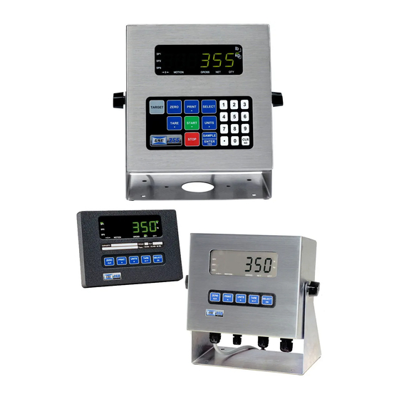
GSE 350 I.S. Technical Reference Manual (151 pages)
INTRINSICALLY SAFE INDICATOR
Brand:
GSE
| Category:
Touch Panel
| Size: 1 MB
Table of Contents
Table of Contents
7
Chapter 1: Introduction
13
Hazardous Area Guidelines
14
Hazard Grouping
14
Duration of Hazard
14
Temperature Codes
14
Definitions
16
Entity Evaluation Concept
16
Entity Rating Definitions
17
Entity Ratings
17
Factory Mutual Approval
18
NEMKO Approval (ATEX)
19
CSA Approval
20
Standard Functions
21
Standard Features
21
Specifications
21
Display
22
LED Display
22
LCD Display
22
Annunciators
22
350 I.s. Keypad
23
Secondary Functions
23
355 I.S. Keypad
24
Weigh Mode Functions
26
Entering a Tare Value (Model 350)
26
Entering a Tare Value (Model 355)
26
Chapter 2: Installation
27
System Diagrams
28
Outline Drawings
28
Load Cell Connections
29
Communication Port Connections
30
Remote Key Connections
30
Remote Display Connections
31
Hazardous Area Options
31
Battery Power Supply (External)
31
AC to DC Power Supply (External)
32
AC to DC Power Supply Extension Cable
32
Volt and 8 Volt Excitation
32
Fiber-Optic Interface
32
Safe Area Options
33
Safe Area Hub Kit
33
Safe Area Analog Option Installation
38
Chapter 3: Configuration
43
Entering the Setup Mode (Model 350 I.S.)
44
Entering the Setup Mode (Model 355 I.S.)
45
Selecting a Parameter
45
Changing a Parameter Value
46
Selection Parameters
46
Key-In Parameters
47
Saving Parameters
48
Factory Default
50
List of Parameters
51
Parameter Map Details
53
Preset Transmit Selections
60
ID Number Entry and Printing
61
Custom Transmit
62
Elements of a Custom Transmit
62
Writing a Custom Transmit ASCII Text File
63
Access Setup and Clearing Existing Custom Transmit
63
Entering ASCII Text
63
Entering ASCII Control Codes
63
Parameter Selection Numbers
65
Exiting Setup Mode and Saving Changes
66
Parts Counting
66
Setpoint Setup
67
Activation Methods (General)
68
Pre-Acts (General)
69
Learn Feature (General)
69
Pause Feature (General)
69
Changing Targets from the Weigh Mode (General)
70
Change Target Weight Example (General)
70
Bargraph Setup (LCD)
71
Scaling for "Bars" (Bargraph Arrows)
71
Percentage Check-Weighing
74
Setpoint Activation (Percentage Check-Weighing)
74
Changing Targets from the Weigh Mode (Percentage Check-Weighing)
74
Example (Percentage Check-Weighing)
75
Fill
75
Activation Method (Fill)
76
Pre-Acts (Fill)
76
Learn Feature (Fill)
76
Pause Feature (Fill)
77
Changing Targets from the Weigh Mode (Fill)
77
Example (Fill)
77
Batch
77
Activation Method (Batch)
78
Pre-Acts (Batch)
78
Learn Feature (Batch)
78
Pause Feature (Batch)
78
Changing Targets from the Weigh Mode (Batch)
78
Example (Batch)
79
Discharge
79
Activation Method (Discharge)
80
Pre-Acts (Discharge)
80
Learn Feature (Discharge)
80
Pause Feature (Discharge)
80
Changing Targets from the Weigh Mode (Discharge)
81
Example (Discharge)
81
Both
81
Activation Method (Both)
82
Pre-Acts (Both)
82
Learn Feature (Both)
82
Pause Feature (Both)
82
Changing Targets from the Weigh Mode (Both)
83
Example (Both)
83
Absolute Check-Weighing
83
Setpoint Activation (Absolute Check-Weighing)
84
Changing Targets from the Weigh Mode (Absolute Check-Weighing)
84
Example (Absolute Check-Weighing)
85
Independent Setpoint Operation
85
Setpoint Activation (Independent)
86
Changing Targets from the Weigh Mode (Independent)
86
Example (Independent)
87
Target Deviation Check-Weighing
87
Setpoint Activation (Target Deviation Check-Weighing)
87
Changing Targets from the Weigh Mode (Target Deviation Check-Weighing)
88
Example (Target Deviation Check-Weighing)
89
Time and Date Setup (Model 350 I.S.)
89
Time and Date Setup (Model 355 I.S.)
91
Remote Key Configuration
92
Upgrade Indicator Firmware
92
Prepare for Upgrade
93
Load Flash File
93
Analog Output Setup
94
Analog Output Calibration
94
Entering Analog Calibration Values
95
Analog Output Example
96
Remote Display Configuration
96
Master to Remote (Slave) Configuration
96
Setup Master Indicator
97
Setup Remote Indicator
97
Control (Hazardous Area) to Hub (Safe Area) Configuration
101
300 Series Command Codes
102
Display Capture Utility
103
Chapter 4: Calibration
105
Setup Mode Calibration
106
Fast Calibration
106
Performing Calibration
106
Establishing Zero
106
First Zero
107
Last Zero
108
False Zero
110
Only Zero
112
Reset Calibration
113
Multi-Point Linerization
115
First Zero
115
Reset Cal
115
Examining Calibration Results
116
Establishing a Span
116
Exiting Calibration
117
Chapter 5: Legal for Trade
119
NTEP Requirements
120
OMIL Requirements
120
Other Requirements
120
Sealing and Audit Trails
121
Physical Seal
121
Audit Trails
122
OIML Audit Trail
122
Calibration Audit Trail
122
Setup Audit Trail
122
Viewing Audit Trail Parameters
122
Chapter 6: Troubleshooting
125
Error Messages
126
Operational Errors
126
Setup Mode Errors
126
Hardware Errors
127
Calibration Errors
127
Communication Errors
127
Miscellaneous Errors
127
Viewing Setup
128
Information Mode Parameters
128
A/D Calibration Procedure
130
Appendix A: Maintenance
133
Main Board Replacement
134
Main Board Removal
134
Main Board Installation
134
Keypad Replacement
134
Model 350 I.S. Keypad Removal
134
Model 355 I.S Keypad Removal
134
Model 350 I.S. Keypad Installation
135
Model 355 I.S. Keypad Installation
135
Display Replacement
135
Display Removal
135
Display Installation
136
Appendix B: Label Drawings
137
Appendix C: Control Drawings
147
Advertisement
GSE 350 I.S. Technical Reference Manual (101 pages)
INTRINSICALLY SAFE INDICATOR
Brand:
GSE
| Category:
Touch Panel
| Size: 2 MB
Table of Contents
Table of Contents
4
Chapter 1:Introduction H a Zar Do U S a
8
R E a G U ~ ~ E ~ ~ E S
8
Hazard Grouping
8
Duration of Hazard
9
Temperature Codes
9
Definitions
11
Entity Evaluation Concept
11
Entity Rating Definihons
12
Entiry Rarings APPROVAW
13
Standard Functions
14
Specifications
14
Display
15
LED Display
15
LCD Display
16
Annunciators
16
Is Keypad
16
Keyp
18
Weigh Mode Functions
19
2: Installation
20
System Diagrams
20
Outline Drawings
20
L O Ad Cell C O N N Ec Ti O N S
21
Connection
21
Aremote Key Connfltions
22
C O N N ~ I O N S
22
Hazardous Area Options
23
Battery Power Supply
23
AC to DC Power Supply (External)
23
Area Option
23
Volt and 8 Volt Excitation
24
Chapter 3: Configuration
25
Entering the Setup Mode
25
Selecting a Parameter
26
C H an G in G a P a Rameterv
28
Selection Parameters
28
I N P ~ a M E T E R S
28
Saving Parameters
29
Factory Default
31
List O F Parameters
32
Parameter Map Details
34
Preset TRANSMIT SELECTIONS
39
Custom
39
Elements of a Custom Transmit
41
Writing a Custom Transmit ASCZZ Textfile
41
Entering ASCII Text
42
Entering ASCII Control Codes
42
Parameter Selecrion Numbers
44
Parts Counting
45
Activation Methods (General)
47
Pre-Acls (General)
48
Feature (General)
48
Pause Fearure {General)
48
Changing Targets from the Weigh Mode (General)
49
Change Target Weight
50
Bargraph (General)
50
Setpoint Activation {Percentage Check- Weighing)
53
Changing Targets from the Weigh Mode (Percentage Check- Weighing)
53
Er C Enta G E
54
Example (Percentage Check- Weighing)
54
Example (Fill)
54
Activation Merhod (Fill)
55
Pre-Acts (Fill)
55
Pause Feature (Fill)
56
Changing Targets from the Weigh Mode (Fill)
56
Batch
56
Activation Method (Batch)
57
Pre-Acts (Batch)
57
Feature (Batch)
57
Pause Feature
57
Changing Targets from the Weigh Mode (Batch)
57
Discharge
58
Activation Method (Discharge)
59
Pre-Acts (Discharge)
59
Learn Feature (Discharge)
59
Target Changesfrom (He Weigh Mode (Discharge)
60
Example (Discharge)
60
Both
60
Activation Method (Both)
61
Pre-Acts (Both)
61
Pause Feature (Borh)
62
Target Changesfrom the Weigh Mode
62
Example (Borh)
62
Absolute Check- Weighing
62
Example (Absolure Check-Weighing)
64
Independent Setpoint Operation
64
Setpoint Activation {Independent)
65
Changing Targets from the Weigh Mode (Independent)
65
Example (Independent)
66
Target
66
Percentage.
66
Changing Targets from Rhe W E I G H Mode (Target Deviation Check- Weighing)
67
Setpoint Activation
67
Example (Target Deviation Check- Weighing)
68
Bargraph Setup (Lcd)
68
TIME and D ATE Seitl.jp (MODEL 350 1S)
70
Time and Remo te Key Oper a Ti O N
72
R E Mote Ser Ia L O Per a Tion
73
Display Capture Ufdity
74
M Wa Re
74
Prepare for Upgrade
75
Load Flash File
75
Chapter 4: Calibration
76
Fast Calibration
76
Performing Calibration
76
Establishng Zero
77
First Zero
77
Last Zero
79
False Zero
81
Only Zero
83
Reset Calibration
84
Aspan
86
Exiting Calibration
87
Chapter 5: Legal for Trade
89
NTEP Requirements
89
O M L R E Q U Ir Eme N T S
89
Sea L in G and a U Dit Trau
90
Physical Seal
91
Audit Trails
91
Chapter 7: Troubleshooting
93
Err0 Rs
93
Operation a Setup Mode Errors
94
Rr O R
95
Calibration Errors
95
Communication Errors
95
Miscellaneous Errors
95
Viewing
95
Srrup
96
Parameters
96
Mode
96
A/D Calibration Procedure
98
Advertisement
Related Products
GSE 355 I.S.
GSE 355
GSE 370
GSE 375
GSE 350
GSE 351
GSE 250
GSE Categories
Scales
Touch Panel
Controller
Accessories
Laboratory Equipment
More GSE Manuals
Login
Sign In
OR
Sign in with Facebook
Sign in with Google
Upload manual
Upload from disk
Upload from URL