
Related Manuals for Renu Electronics GWY-900

Summary of Contents for Renu Electronics GWY-900
-
Page 1: User Manual
USER MANUAL GSM Gateway Installation and configuration of the GSM Gateway on a FlexiSoft Software ®... -
Page 3: Revision History
REVISION HISTORY: A manual revision code appears to the bottom of this manual and on the front cover of the manual. Doc. No.: UM-GWY-900-0811 Ver.: 1.00D The following table outlines the changes made to the manual during each revision. Revision code... -
Page 4: Table Of Contents
Contents PRECAUTIONS ....................5 Intended Audience ....................6 Purpose and scope of this Manual ................ 6 General Precautions ..................... 6 Safety Precautions ....................7 Caution ......................... 7 INTRODUCTION ..................... 9 Purpose of this manual ..................10 1.1.1 GSM Gateway Basics ..................10 1.1.2 Hardware Requirements .................. -
Page 5: Precautions
Safety Precautions PRECAUTIONS This section provides general precautions for using the GSM gateway series units viz.: GWY-900 and GWY-910. The information contained in this section is important for the safe and reliable application of the Unit. You must read this section and understand the information contained before attempting to set up or operate a unit. -
Page 6: Intended Audience
• Be trained in rendering first aid. Purpose and scope of this Manual Thank you for purchasing the GSM gateway product from Renu Electronics Pvt. Ltd. GWY-900 ® and GWY-910 products are configured with Microsoft Windows based software “FlexiSoft ”. -
Page 7: Safety Precautions
Safety Precautions WARNING It is extremely important that the unit and other peripherals be used for the specified purpose and under the specified conditions, especially in applications that can directly or indirectly affect human beings. WARNING Do not use input functions as PT touch switches for applications where danger to human life or serious damage is possible, or for emergency switch applications. - Page 8 Safety Precautions • Store in a cool, clean, and dry location. Avoid storage locations with extreme temperatures, rapid temperature changes, high humidity, moisture, dust, corrosive gases, or metal particles. • Do not store the unit in places that are exposed to outside weather conditions (i.e., wind, rain, snow, etc.).
-
Page 9: Introduction
Introduction INTRODUCTION In this chapter..♦ Purpose of this manual GSM Basics Hardware Configuration ♦ Product Overview SMS Messaging Configuration ♦ Product Specifications... -
Page 10: Purpose Of This Manual
1.1.1 GSM Gateway Basics GWY-900 / GSM-910 is a Data sharer/Protocol Converter for devices like PLCs, Inverters, and Controllers etc. GSM Gateway has a serial port, which connects to a serial device and a GSM port that connects to GSM network. -
Page 11: Gwy-9Xx Applications
Introduction 1.1.3 GWY-9xx Applications (I) PLC to midpoints Communication: (ii) PLC to PLC communication (iii) Add IO to PLC:... -
Page 12: Overview
Introduction 1.2 Overview The GWY-9xx module communicate using the Global System for Mobile Communication (GSM) network. This wireless network is the same network that supports cellular telephones, providing communication access from virtually anywhere. Note: Not all areas have the GSM infrastructure in place. REPL is not responsible and cannot be held liable for providing / supporting the network infrastructure. -
Page 13: Specifications
+80 Humidity: 10% to 90% (Non condensing) Mounting: DIN rail or back panel mounting Dimensions (mm): For GWY-900: 100mm(H) X 36mm(W) X 70mm(D) For GWY-910: 100mm(H) X 26mm(W) X 70mm(D) Weight: 150 gm approx. Certifications: CE, UL, RoHS compliant... -
Page 14: Installation And Connection
Installation and connection INSTALLATION AND CONNECTION In this chapter..♦ Installing module on the mounting rail ♦ Removing module from the mounting module ♦ Power Connection... -
Page 15: Installation Instruction
Particular care should be taken to locate variable speed drives and switching power supplies away from the unit. 3.1.1 Panel Mounting This section presents the dimensional sketches and din rail sliding for GWY-xxx models. (All dimensions are in mm and drawing are not to scale.) For GWY-900: For GWY-910:... - Page 16 Installation and connection GWY-900 unit with DIN rail slider Front View Rear View GWY-910 unit with DIN rail slider Front View Rear View...
-
Page 17: Removing Module From The Mounting Module
Installation and connection Steps to mount the unit on DIN rail plate FIG-1 FIG-2 FIG-3 FIG-1 Pull up the sliders provided with the GWY-9xx towards outward direction. FIG-2 Rest the unit on the DIN rail plate FIG-3 Pull down the slider again so that unit can fix up with the DIN rail plate Removing module from the mounting module To remove the unit from the mounting module, follow the below given steps: 1. -
Page 18: Power Connection
Installation and connection Power Connection If wiring is to be exposed to lightening or surges, use appropriate surge suppression devices. Keep AC, high energy and rapidly switching DC wiring separate from signal wires. Connecting high voltages or AC power mains to the DC input will make unit unusable and may create an electrical shock hazard to personnel. -
Page 19: Usb Device
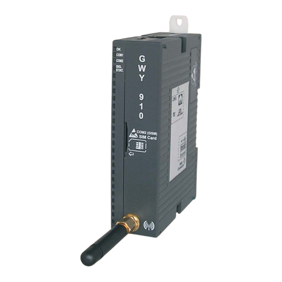
Note: This port is available on with GWY-910 product. Antenna Connection To access the GSM network, an antenna must be connected to the GWY-900 unit. Antenna will be provided with each unit in the packing box. Attach the antenna to the end of the module. The antenna should be mounted in a clear area where limited interference will occur. -
Page 20: Sim Card Installation
Installation and connection SIM Card Installation Each GWY-9xx unit requires a SIM card. Note: The SIM card must be obtained locally and be compatible with a local service provider’s towers. Addition- ally, the plan purchased from the service provider must include SMS messaging (texting). Not all service providers utilize a GSM network for texting. -
Page 21: Led Indicators
Installation and connection LED Indicators LEDs on the GWY-9xx module, indicate the following: LED Status Indication Steady ON Gateway ON (CPU ON) Gateway OFF (CPU OFF) If other LEDs are seen ON or Blinking, then OK LED is damaged. COM1 Blinking slow (ON-OFF) Communication error at COM1 at every 250 ms... -
Page 22: Sample Application
® Application Development in Flexisoft SAMPLE APPLICATION In this chapter..♦ Creating sample application ♦ Ladder Logic ♦ Slave application for GWY-9xx... -
Page 23: Creating Sample Application
Also in FlexiSoft , two sample applications are provided which clears the operation of sending SMS. The application describes here is shown with GWY-900 unit. Here GWY-900 sends the data of FP5043TN-E (HMI) to user’s mobile. viz.: “FP5043TN-E.pzm” and “ModbusRTUMaster_GWY-900.pzm”... - Page 24 ® Application Development in Flexisoft 2) Go to COM1 from Node Configuration window, add nodes with protocol (example: Modbus Master RTU) & configuration settings on COM1. User can add multiple nodes one by one. Refer below image:...
- Page 25 ® Application Development in Flexisoft 3) Go to COM2 from Node Configuration window. On creation of new project of GWY-900, GSM Driver will be automatically added here. Configuration settings are fixed for COM2. Hence only single node is supported. Refer below given image: 4) Once COM1 and COM2 are defined, you can see the default tags in taglist.
-
Page 26: Gwy-9Xx System Tag Information
® Application Development in Flexisoft 4.1.1 GWY-9xx system tag information: Tag Number High Byte Low Byte SW0049 Mobile Number 2 ASCII Digit Mobile Number 1 ASCII Digit SW0050 Mobile Number 4 ASCII Digit Mobile Number 3 ASCII Digit SW0051 Mobile Number 6 ASCII Digit Mobile Number 5 ASCII Digit SW0052... - Page 27 ® Application Development in Flexisoft 5) User can add tasks to update PLC tags information. Tasks supported for GWY-9xx are as follows: Task Name SMS Screen Tasks Main loop Tasks Before While After Power Global Task Showing Showing Hiding On Task Screen Screen Screen...
- Page 28 ® Application Development in Flexisoft Note: Please do not use the other two options, viz.: “Display Screen” and “Print Screen”. These opions won’t send the message to destination mobile. In the above shown image, a SMS is written using Text and Display Data Entry Objects. When STR (Screen Trigger Register: SW0005) value will be same as the screen number, the screen information will be sent to user defined number.
- Page 29 ® Application Development in Flexisoft 7) Enter an ASCII phone number to screen. Follow below said steps: a) Select the screen which is to be sent. b) Go to task and select “Before showing Screen” task. c) Add task for entering mobile number to which the SMS is to be sent. d) Write mobile number is ASCII format to mobile number default tag registers.
- Page 30 ® Application Development in Flexisoft Hence +919850898116 need to write in following way: Tag Number High Byte (ASCII) Low Byte (ASCII) High Byte (Hex) Low Byte (Hex) Equivalent Hex value SW0049 392BH SW0050 3931H SW0051 3538H SW0052 3830H SW0053 3839H SW0054 3131H SW0055...
-
Page 31: Ladder Logic
® Application Development in Flexisoft Note: Mobile number can be added to Before Showing task for sending SMS to various mobile numbers by entering different mobile number to different screens. Or can be added to Global task for sending SMS to only one mobile number. - Page 32 ® Application Development in Flexisoft Here if B00000 is ON then screen 2 is moved to Screen Trigger Register i.e. Screen 2 is sent to +919850898116. Here if B00010 is ON then screen 3 is moved to Screen Trigger Register i.e. Screen 3 is sent to +917350017544.
-
Page 33: Steps To Create Slave Application For Gwy-9Xx
® Application Development in Flexisoft Steps to create slave application for GWY-9xx Refer application “FP5043TN-E_GWY-900.pzm”. 1) Create new project for FP5043TN-E 2) Add node of Modbus RTU (Unit as a Slave) with same setting as a Modbus RTU (Unit as a Master). 3) At Screen no.1, SMS sending logic, define data entry (Pressure, Temperature, volume tags which are mapped) which is to be sent to the SMS. -
Page 34: Miscellaneous
Miscellaneous MISCELLANEOUS In this chapter..♦ SMS Sending Operation ♦ SMS Receiving Operation ♦ Online Ladder Monitoring... -
Page 35: Sms Sending Operation
Miscellaneous SMS Sending Operation To send SMS, follow below given steps. 1) Write mobile number in ASCII digit format into Mobile number tags (SW0049 to SW0056). Mobile number should conatain ‘+’ sign at start, with country code & actual mobile number. User can write fix destination mobile number digits into it or can update these Mobile number tags (SW0049 to SW0056) using external PLC tags. -
Page 36: Sms Sending Operation To Multiple Mobile Numbers
Miscellaneous SMS Sending Operation to multiple mobile numbers: To send a SMS to multiple mobile number, user needs to add one SMS Screen with Display Screen option at right as shown here: To send SMS user needs to follow below steps. a) Write mobile number in ASCII digits into Mobile number tags (SW0049 to SW0056). -
Page 37: Sms Receiving Operation
Miscellaneous SMS Receiving Operation: Tag memory is given to Store received SMS from external GSM device. User can copy it, can take action on it. Received Message information will be written in following Data Register Tags. S00056 (Coil) - Received Message Ready Flag. It will become 1 when message received. It will be clear after one main loop cycle. -
Page 38: Online Ladder Monitoring
Miscellaneous Online Ladder Monitoring On line ladder monitoring is used to monitor ladder logic blocks running in device. It can also be used as a debug tool for debugging the ladder logic diagram. This functionality is available only with GWY-910 model. Flexisoft software operates in three modes: (i) Offline Mode (ii) Online mode... - Page 39 Miscellaneous b) Monitor without upload: Go online with offline project. Select "Without Upload" option from Mode menu. Mode -> Online -> Without Upload. In this mode, PC software starts monitoring Logic blocks from current active project. Project must have logic blocks defined in order to start monitoring.
- Page 40 Miscellaneous Port selection settings are applicable only for serial communication. For monitoring through serial port user needs to configure ‘Serial Monitor’ driver either on COM1 or COM2 and also applicable for serial monitoring ‘With Upload’ feature (Serial Monitor driver should be present in the application while user using monitor ‘with upload’...
-
Page 41: Appendix
Miscellaneous APPENDIX In this chapter..♦ Force Download Mode ♦ Default Settings ♦ Communication Cable... -
Page 42: I] Force Download Mode
Miscellaneous Force Download Mode In case the GWY-9xx is not responding for the firmware download command and when it does not allow the further download in the unit, unit can be driven in the Force download mode. Follow the following step to enter the force download mode. -
Page 43: Ii] Appendix A: Default Settings
Miscellaneous Appendix A: Default Settings While creating application for GWY-9xx in FlexiSoft ® , keep the deafult settings as given below: Default “Upload from device” Properties if user selects port “Serial”: Mode: Serial Project: Application + Ladder Device settings: Unit in HALT Mode Unit in RUN Mode Default “Download to device”... - Page 44 Miscellaneous ® While creating application for GWY-9xx in FlexiSoft , keep the deafult settings as given below: Default “Upload from device” Properties if user selects port “USB”: Mode: Project: Application + Ladder Device settings: Unit in HALT Mode Unit in RUN Mode Default “Download to device”...
-
Page 45: Iii] Appendix B: Communication Cable
Miscellaneous III] Appendix B: Communication cable Programming cable for GWY-9xx unit (IBM-H-005-00): FlexiLogics ® SIDE PC SIDE 2 mtr. R.H.S. VIEW FRONT VIEW Pin 1 Pin 8 (Left (Right side) side) DB9 FEMALE PINOUTS 8 PIN MODULAR CONNECTOR PINOUTS Signals Pin# Pin# Signals... - Page 46 Please contact factory for more information HEAD OFFICE: FACTORY: Survey No. 2/6, Baner Road, Pune - 411045, India. Gat No. 1163, Village - Ghotawade, Tel : +91 20 2729 2840 Fax : +91 20 2729 2839 Tal - Mulshi, Pune 412115, India. Email : info@renuelectronics.com Tel: +91 20 6687 2900 Website: www.renuelectronics.com...
Need help?
Do you have a question about the GWY-900 and is the answer not in the manual?
Questions and answers