Table of Contents
Advertisement
Quick Links
PCE Americas Inc.
PCE Instruments UK Ltd.
711 Commerce Way
Units 12/13
Suite 8
Southpoint Business Park
Jupiter
Ensign way
FL-33458
Hampshire / Southampton
USA
United Kingdom, SO31 4RF
From outside US: +1
From outside UK: +44
Tel: (561) 320-9162
Tel: (0) 2380 98703 0
Fax: (561) 320-9176
Fax: (0) 2380 98703 9
info@pce-americas.com
info@pce-instruments.com
www.pce-instruments.com/english
www.pce-instruments.com
Manual
Digital Thermometer PCE-T 390
Version 2.1
Date of creation: 04.12.2015
Date of last change: 19.05.2016
Advertisement
Table of Contents

Related Manuals for PCE Instruments PCE-T 390


Summary of Contents for PCE Instruments PCE-T 390
- Page 1 From outside UK: +44 Tel: (561) 320-9162 Tel: (0) 2380 98703 0 Fax: (561) 320-9176 Fax: (0) 2380 98703 9 info@pce-americas.com info@pce-instruments.com www.pce-instruments.com/english www.pce-instruments.com Manual Digital Thermometer PCE-T 390 Version 2.1 Date of creation: 04.12.2015 Date of last change: 19.05.2016...
-
Page 2: Table Of Contents
10 Battery replacement ....................11 11 RS232 PC serial interface ..................11 12 Offset adjustment ....................12 13 Optional type K temperature probe ..............14 14 Patent ........................14 15 Contact ........................15 15.1 PCE Instruments UK ......................15 15.2 PCE Americas ........................15... -
Page 3: Introduction
Please read this manual carefully and completely before you use the device for the first time. The device may only be used by qualified personnel and repaired by PCE Instruments personnel. There is no warranty of damages or injuries caused by non-observance of the manual. -
Page 4: Specifications
Manual Specifications General Circuit Custom one-chip microprocessor LSI circuit Display LCD size : 52 mm x 38 mm LCD with green backlight ( ON/OFF) Channels T1, T2, T3, T4, T1-T2 Sensor type Type K thermocouple probe Type J/T/E/R/S thermocouple probe. PT 100 Ohm probe * works with an 0.00385 alpha coefficient, meet DIN IEC 751. - Page 5 Manual Temperature Automatic temperature compensation for the compensation K/J/T/E/R/S type thermometer Linear Linear compensation for the full range compensation Offset Available for K/J/T/E/R/S type and Pt 100 Ohm adjustment Probe input K/J/T/E/R/S type socket 2-pin thermocouple socket Pt 100 Ohm : earphone socket Overload Shows "...
- Page 6 Manual Electrical (23 ±5 °C) Pt 100 Ohm: Resolution Range Accuracy -199.9 … 850.0 °C 0.1 °C ± ( 0.4 % + 1 °C ) -327.0 … 999.9 °F 0.1 °F ± ( 0.4 % + 1.8 °F) 1000 … 1562 °F 1 °F ±...
-
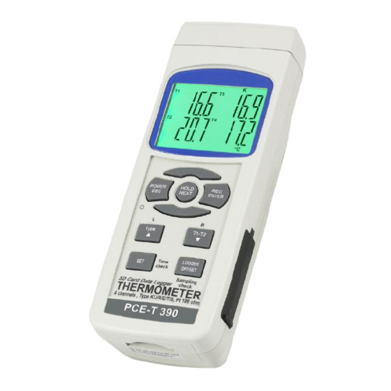
Page 7: System Description
Manual System description 4-1 Display 4-2 Power button (ESC, backlight button) 4-3 Hold button (Next button) 4-4 REC button (Enter button) 4-5 Type button (▲ button, L button) 4-6 T1-T2 button (▼ button, R button) 4-7 SET button (time check button) 4-8 Logger button (OFFSET button, sampling time check button) 4-9 T1, T2, T3, T4 input socket (type K, type J) 4-10 PT1 input socket (Pt 100 Ohm) -
Page 8: Measuring Procedure
Manual Measuring procedure Type K measurement 1) Power on the meter by pressing the "Power button" (3-2) once. * When the meter is powered on, pressing the "Power button" once (>2 s) will turn off the meter. 2) The default temperature sensor type of the meter is the K type sensor; the display will indicate "K". The default temperature unit is °C (°F). -
Page 9: Datalogger
Manual c) To exit the memory record function, press and hold the "REC" button for at least 2 seconds. The display will revert to the current reading. LCD Backlight ON/OFF After turning the power ON, the "LCD Backlight" will be activated automatically. During the measurement, press the "Backlight Button"... -
Page 10: Saving Data From The Sd Card To The Computer (Excel Software)
Manual SD card data structure 1) When SD card is used with the meter for the first time, the SD card will generate a folder: TMA01. 2) If you execute the datalogger function for the first time, under the route TMA01\, a new file called TMA01001.XLS will be generated. -
Page 11: Power Supply From Dc Adaptor
Manual 2) After setting the upper text to "bASI" or "Euro", pressing the "Enter Button" (4-4) will save the setting function as default. Auto power OFF When the lower display shows "PoFF", 1) use the "▲ Button" (4-5) or the "▼ Button" (4-6) to set the upper value to "yES" or "no". yES - Auto Power Off enabled no - Auto Power Off disabled 3) After selecting "yES"... -
Page 12: Offset Adjustment
Manual serial port. The 16 digits data stream will be displayed in the following format: D15 D14 D13 D12 D11 D10 D9 D8 D7 D6 D5 D4 D3 D2 D1 D0 Each digit indicates the following status: Start Word When showing the upper display data = 1 When showing the lower display data = 2 D12, D11 Fault alarm system for display... - Page 13 Manual * Use the "▲ button" (4-5) and the "▼ button" (4-6) to adjust the desired value on the right bottom of the display. * When you press the "Enter button" (4-4) once, the adjusted value will be saved into the memory and then the device will return to the normal measuring screen and finish the offset adjustment procedure.
-
Page 14: Optional Type K Temperature Probe
Manual 13 Optional type K temperature probe (Type K) TP-01 * Max. short-term operation Temperature: 300 °C (572 °F) * Ultra-fast response thermocouple suitable for many general purpose applications * Meas. range: -50 … 900 °C, Thermocouple probe -50 … 1650 °F (Type K), TP-02A * Dimensions: 10 cm tube, ø... -
Page 15: Contact
Manual 15 Contact If you have any questions about our range of products or measuring instruments please contact PCE Instruments. 15.1 PCE Instruments UK By post: PCE Instruments UK Ltd. Units 12/13 Southpoint Business Park Ensign Way, Southampton Hampshire United Kingdom, SO31 4RF...
Need help?
Do you have a question about the PCE-T 390 and is the answer not in the manual?
Questions and answers