Photron FASTCAM Multi Hardware Manual
Hide thumbs
Also See for FASTCAM Multi:
- User manual (36 pages) ,
- Hardware manual (33 pages) ,
- First step manual (36 pages)
Table of Contents
Advertisement
Quick Links
Download this manual
See also:
User Manual
Advertisement
Table of Contents

Related Manuals for Photron FASTCAM Multi


Summary of Contents for Photron FASTCAM Multi
- Page 2 The copyright of this manual is held by PHOTRON LIMITED. Product specifications and manual contents are subject to change without notice. PHOTRON LIMITED bears no responsibility for any results by using our products nor by applying this manual to any operations.
- Page 3 This manual contains the operating instructions and warnings necessary for using the system. Before using the system, please read the entire manual. If any part of this manual is unclear, contact Photron using the contact information printed at the back of the manual.
- Page 4 This chapter explains the system’s specifications. Chapter 6. Warranty This chapter explains about the warranty. Chapter 7. Contacting Photron This chapter lists the contact information to use when contacting Photron if the system malfunctions or if a portion of the manual is unclear.
- Page 5 In order to prevent injury to yourself and others, and to prevent damage to property, carefully observe the following safety precautions. Photron has given its full attention to the safety of this system. However, the extent of damage and injury potentially caused by ignoring the content of the safety precautions and using the system incorrectly is explained next.
- Page 6 Warning ■ Do not perform actions that will damage the AC cable or plug. (Do not damage the cable, modify it, use it near a heater, excessively bend, twist or pull on it, place heavy objects on it, or bundle it.) Using the cable when damaged can cause fire, electric shock, or a short circuit.
- Page 7 Caution ■ Always unplug the system when cleaning it or when it is unused for a long period of time. Leaving or storing the system connected to the power source might cause fire from insulation deterioration or electrical discharge. ■Please consult us in advance when you perform an event by which laser light or direct rays fall on the image sensor surface.
- Page 8 For more information about the recycling of this product, please contact your local city office, waste authority, approved scheme or your household waste disposal service or visit www.photron.com. (EEA: Norway, Iceland and Liechtenstein) This product is in conformity with the protection requirements of EU Council Directive 2014/30/EU (Class A) on the approximation of the laws of the Member States relating to electromagnetic compatibility.
- Page 9 Cleaning of the Image Sensor Surface Electrostatic Discharge (ESD) events may cause immediate and unrecoverable damage to the image sensor. Please read the following instructions and take EXTREME CARE when cleaning the image sensor surface. ■ ALWAYS take appropriate anti-static precautions when cleaning or working near the Image sensor.
- Page 10 Camera Cable ■ Minimum curve radius of the camera cable is 125mm. Be careful when using or storing camera cable to give an ample space for the curvature. ■ Do not give an excessive impact or load to camera cables to avoid damage. ■...
-
Page 12: Table Of Contents
Table of Contents Chapter 1. Overview 1.1. Product Overview and Features ................2 Chapter 2. Setup 2.1. System’s Components and Accessories ..............4 2.1.1. Components ....................4 2.1.2. Type ......................4 2.2. Accessories/Options ....................5 2.2.1. Camera Head ....................5 2.2.2. - Page 13 Synchronization with a variable frequency ..........33 4.3.4. Synchronizing Multiple FASTCAM Multi Systems (Multiple Unit Synchronized Recording) ............. 34 4.3.5. Synchronizing FASTCAM Multi with Other External Devices (Frame Rate Synchronized Recording) ............ 36 4.3.6. Synchronizing the System with Other Cameras (Mixed Device Synchronized Recording) ..........38 4.4.
- Page 14 7.1. Contact Information....................66...
-
Page 15: Chapter 1. Overview
Chapter 1. Overview 1.1. Product Overview and Features... -
Page 16: Product Overview And Features
The system is not only equipped with input/output terminals for triggering and synchronizing with external devices, but also supports a variety of functions such as video output and Gigabit Ethernet control by a PC and Remote Controller (Optional). Photron has software for control, image analysis, and processing. -
Page 17: Chapter 2. Setup
Chapter 2. Setup 2.1. System’s Components and Accessories 2.2. Accessories/Options 2.3. Part Names... -
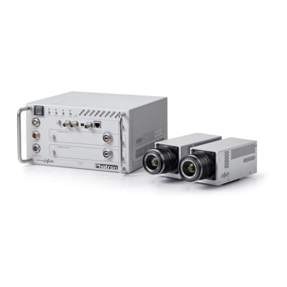
Page 18: System's Components And Accessories
Subject to restrictions under Export Trade Control Order, your camera may NOT be used depending on the country where you intend to use. If you are considering using your camera outside Japan, check with Photron first. Contact information is given in 7.1 Contact Information. ... -
Page 19: Accessories/Options
Subject to restrictions under Export Trade Control Order, your camera may NOT be used depending on the country where you intend to use. If you are considering using your camera outside Japan, check with Photron first. Contact information is given in 7.1. Contact Information. 2.2.2. Camera Cable... -
Page 20: Led Light
Micro Four Thirds Lens Option For FASTCAM Multi (102484) This is the lens mount, to be fitted to the camera head, to take the Micro Four Thirds lens. Refer to “Micro Four Thirds Lens Option For FASTCAM Multi Hardware Manual”. 2.2.5. Remote Controller Remote Controller These are the external control, to be used in connection with the body. -
Page 21: Part Names
2.3. Part Names This product comprises the following components: the camera and processor, AD adapter and control software [The Photron FASTCAM Viewer (“PFV” hereinafter)]. It is used in conjunction with various optional items as necessary. For each of the system components. -
Page 22: Main Unit Part Names
Chapter 2 Setup FASTCAM Multi Main Unit (FAST Drive) 2.3.2. Main Unit Part Names Status LED POWER SW Gigabit Ethernet USER SW LAN Cable Connector KEYPAD ANALOG IN2 HD-SDI I/O PORT ANALOG IN1 Mini DisplayPort Camera Cable Connector DC-IN Front Side... - Page 23 Camera cable FAST Drive Connector 1 Connector I/O PORT HD-SDI FAST Drive Connector 2 DC-IN Mini DisplayPort Front Side Above red marked six knobs are only for Photron service engineers. Do Not loosen or remove them. FASTCAM Multi Hardware Manual...
-
Page 24: Main Power Switch
Chapter 2 Setup 2.3.3. Main Power Switch This is the main power switch for the processor. To turn the unit on or off, press the ON/OFF switch with the cover flipped up. The power status is shown as follows: Indicator off: Power to the system is off. Indicator ON (green): Power is on, that is the camera head is active with power. -
Page 25: Status Leds On The Front Side
LED FLASHING: ENDLESS recording (The REC (Red) LED is also flashing) LED OFF: Not ready to record REC (Red) LED ON: Ready to record (The case of “ENDLESS” recording mode) LED FLASHING: Recording LED OFF: Not recording FASTCAM Multi Hardware Manual... - Page 26 Chapter 2 Setup Illumination/blinking in operational states During low light mode Operation LEDs other than POWER (green) and IF LINK/TRANS (red) blink at a regular interval. During the Gigabit Ethernet interface initialization LEDs other than POWER (green) and IF LINK/TRANS (red) blink alternately from right to left and from left to right a number of times.
-
Page 27: Remote Controller (Optional)
The Remote Controller is optional. It is not included in the standard configuration. For how to operate of the Remote Controller, refer to the "Remote Controller User's Manual". For the dimensions of the Remote Controller, refer to “5.2.2 Remote Controller (Optional)” page 58. FASTCAM Multi Hardware Manual... -
Page 28: I/O Port Connector
Chapter 2 Setup 2.3.6. I/O PORT Connector The input/output signal connectors on the system have been bundled into a single connector, the "I/O PORT" connector, and it is possible to connect to and access each type of signal by using the specialized multi-connector. - Page 29 SYNC IN TRIGGER TTL IN TRIGGER TTL ECJ.2B.326.CLD FGJ2B326CLLD92Z I/O PORT (LEMO) (LEMO) GENERAL OUT1 RESERVE RESERVE RESERVE GENERAL IN TRIGGER SW Pin 3, 15, 16, 19, 26's GND signal is the common ground for BNC. FASTCAM Multi Hardware Manual...
-
Page 30: Power Supply Connector
Chapter 2 Setup 2.3.7. Power Supply Connector The DC power supply input connector. Connect to the supplied AC adapter or the optional High-G Battery. The cable connector is optionally available. When using other power supplies, construct a cable using the pin diagram below as a reference. DC20-34V 180VA Pin Diagram ECJ.2B.304.CLD Camera Body Connector... -
Page 31: Chapter 3. System Connections
Chapter 3. System Connections 3.1. Camera Head Connection 3.2. AC Power Supply Connection 3.3. Remote Controller Connection (Optional) 3.4. PC Connection 3.5. Video Monitor Connection... -
Page 32: Camera Head Connection
Chapter 3 System Connections 3.1. Camera Head Connection Following the below steps, connect between the Main Unit and a camera head using the dedicated cables. Make sure the power to Main Unit is off. Grasp and slide the grip of the connector, and then remove the cap from the camera cable. Connect the caps each other to avoid dirt and pollution and to keep clean inside. - Page 33 Be sure to shut down the Main Unit before connecting or disconnecting the camera head. If the camera head is connected or disconnected while the system is powered, an error will result. FASTCAM Multi Hardware Manual...
-
Page 34: Ac Power Supply Connection
Chapter 3 System Connections 3.2. AC Power Supply Connection Connect the supplied AC power supply unit to the power supply. 1, 7 Confirm the Power SW is turned off. Connect the options/accessories. Connect the AC power supply unit to the “DC20-34V 180VA” connector on the front of the Main Unit. -
Page 35: Remote Controller Connection (Optional)
No use The Remote controller is hot-pluggable. It can be plugged in and removed while the system's power is on. For how to operate of the Remote Controller, refer to "Remote Controller User's Manual". FASTCAM Multi Hardware Manual... -
Page 36: Pc Connection
1000BASE-T. The maximum length of the cable that connects the system (or PC) to the switching hub is also 100m. For the setting method of control PC, refer to “Photron FASTCAM Viewer User's Manual”. For detail instruction on PC connection setting, refer to “Gigabit Ethernet Interface Connection Tutorial Manual”. -
Page 37: Connecting The Main Unit And A Pc
The IP address can be specified using a remote controller (option) or using the PFV software. For the procedure for setting the IP address of the system, refer to the "Photron FASTCAM Viewer User's Manual" or the “Remote Controller User’s Manual”. -
Page 38: Initializing Gigabit Ethernet Interface And Camera Ip Address
Chapter 3 System Connections 3.4.4. Initializing Gigabit Ethernet Interface and Camera IP Address You could reset the IP address back to the factory setting (192.168.0.10) by going through below steps. This could be useful at times when you could not connect to the camera while running PFV, the product’s control software, or when you accidentally changed your camera’s IP address and lost Out of 4 programmable switches (USER SW) on the front panel, hold either USER1 or USER 4 for at least 10 seconds. -
Page 39: Video Monitor Connection
Use a 5C-FB standard cable for the HD-SDI output. An adapter/equipment for converting to HDMI or DVI-D connector has to be supported the following specification. Convertor type: Passive Other conditions: DP++ (DisplayPort++), supporting signal pass through FASTCAM Multi Hardware Manual... - Page 40 Chapter 3 System Connections...
-
Page 41: Chapter 4. Functions
Chapter 4. Functions 4.1. Input / Output Signals 4.2. External Triggering 4.3. External Synchronization Signals 4.4. GENERAL Signal Setting 4.5. Signal Delay 4.6. Using Programmable Switch (USER SW) 4.7. IRIG Time Code (External Time Synchronization) 4.8. IRIG-sync Operation 4.9. AUTO EXPOSURE Operation 4.10. -
Page 42: Input / Output Signals
Chapter 4 Functions 4.1. Input / Output Signals With the system, many signals can be input and output through the I/O cable. Signals that can be input and output from the I/O cable are listed below. A signal other than the specified signal must not be input to the various connectors. Use extreme caution as there is a risk of damage to both, the input device and the output device. -
Page 43: General Out (1, 2, 3) Connector
READY POS/NEG Outputs a signal that indicates the recording ready state. For details refer to “3.8 Other Settings” of the “Photron FASTCAM Viewer User's Manual”, or “10.6.1 Setting External I/O Port” of “Photron FASTCAM Viewer 4 User’s Manual. FASTCAM Multi Hardware Manual... -
Page 44: External Triggering
For the setting method of the signal inputted into GENERAL IN, refer to “4.4.1.GENERAL IN Signal Setting” page 39. For each external trigger signal input setting refer to “3.8 Other Settings” of the “Photron FASTCAM Viewer User's Manual”, or “10.6.1 Setting External I/O Port” of “Photron FASTCAM Viewer 4 User’s... - Page 45 TRIG TTL IN , GENERAL TTL IN , TRIG SW IN , SYNC IN Circuit Diagram FASTCAM Multi Hardware Manual...
-
Page 46: Outputting External Trigger Signals
Chapter 4 Functions 4.2.2. Outputting External Trigger Signals With the system, you can externally output trigger signals. Output is performed with the TRIG TTL OUT connector's dedicated trigger output system provided by the system, and additionally, output can also be optionally set from the GENERAL OUT connector. External trigger signal output settings are also made by PFV, selecting [TRIG TTL OUT] or [GENERAL OUT] from [Camera Option] –... -
Page 47: External Synchronization Signals
+2.5V to +12V), Positive Polarity (including other Photron products). Synchronizes to a negative polarity signal from FET Input 0V - +12V (H level ON OTHERS an external device (including other Photron +2.5V to +12V), Negative products). Polarity 4.3.2. Outputting External Synchronization Signal The system can externally output a synchronization signal. -
Page 48: Synchronizing Multiple Fastcam Multi Systems
Chapter 4 Functions 4.3.4. Synchronizing Multiple FASTCAM Multi Systems (Multiple Unit Synchronized Recording) The system can perform synchronized recording by synchronizing multiple units using external synchronization input/output. Conceptual Diagram of Synchronous Connection CAMERA No.2 CAMERA No.1 (SLAVE) SYNC IN (MASTER) - Page 49 It is necessary to connect a "Trigger signal" separate from a "Synchronized signal". Please connect a "Trig TTL OUT" on a master camera and "Trig TTL IN" on any slave cameras, if you need to operate multiple camera system with a Trigger signal on a master camera. FASTCAM Multi Hardware Manual...
-
Page 50: Synchronizing Fastcam Multi With Other External Devices (Frame Rate Synchronized Recording)
Chapter 4 Functions 4.3.5. Synchronizing FASTCAM Multi with Other External Devices (Frame Rate Synchronized Recording) With the system, in addition to the frame rate preset in the system, a function has been provided where you can receive a synchronization signal externally; set the frame rate with that frequency, and record. - Page 51 (an error of about ±1-5Hz is produced). For example, when performing external device synchronization inputting a synchronization signal of 10000Hz, the monitor display error is: 10,000 Hz ±1Hz = 9,999 fps to 10,001 fps. FASTCAM Multi Hardware Manual...
-
Page 52: Synchronizing The System With Other Cameras
For camera models that can perform synchronized recording or for detailed instructions on making the settings, contact Photron at the contact information in "7.1. Contact Information” page 66. -
Page 53: General Signal Setting
READY ON/OFF is switched by a pulse input. FET Input 0V - +12V (H level +2.5V to +12V), Negative Polarity When using the camera as a part of a system, verify the characteristics of the input signals before using them. FASTCAM Multi Hardware Manual... -
Page 54: General Out Signal Settings
Chapter 4 Functions 4.4.2. GENERAL OUT Signal Settings Details of the signals output from the GENERAL OUT connector explained in section “4.1. Input / Output Signals” are shown in the chart below. There are three GENERAL OUT connectors and individual settings can be made for each connector. Menu Display Contents Signal Type... -
Page 55: Signal Delay
Example: Frame rate is 1,000fps, SYNC OUT TIMES setting is 4. 1,000fps Synchronization Signal SYNC OUT output An accurate frequency is output, but when SYNC OUT TIMES is set to a large value with a high frame rate, the setting may result in frequency errors. FASTCAM Multi Hardware Manual... - Page 56 Chapter 4 Functions There are following limitations in SYNC OUT TIMES function. Frame Rate Restriction 60,000fps No limit 60,001fps 90,000fps x30 is unavailable 90,001fps 500,000fps x20 and x30 are unavailable 500,001fps 700,000fps x8, x10, x20 and x30 are unavailable 700,001fps Max Frame Rate x6, x8, x10, x20 and x30 are unavailable...
-
Page 57: Using Programmable Switch (User Sw)
Status Displays the status of camera settings on the video output. Live/Memory Switches between LIVE and MEMORY states. Rec Ready Sets the record ready state. Starts recording. Low Light Turns low-light mode ON/OFF. FASTCAM Multi Hardware Manual... -
Page 58: Irig Time Code (External Time Synchronization)
The system supports IRIG-B input and can add an IRIG code to each recorded frame. The sample timing for the IRIG code is once each frame. The recorded IRIG code is displayed on the “Photron FASTCAM VIEWER” software. IRIG Code Input Specification... -
Page 59: Irig-Sync Operation
EXPOSURE : Exposure to the camera sensor (exposure is indicated by high duration) : Camera’s vertical sync signal CAM_V For the settig about the function, refer to "Photron FASTCAM Viewer User's Manual" or "Remote Controller User's Manual". FASTCAM Multi Hardware Manual... -
Page 60: Auto Exposure Operation
Chapter 4 Functions 4.9. AUTO EXPOSURE Operation The system has a function that automatically varies the shutter (the sensor’s exposure time) for the quantity of light input so that it will achieve the desired image output level. After the settings are made once, in a situation where settings cannot be changed, this function displays its effect when recording in an environment where the subject’s amount of light changes. - Page 61 In this case, the variable shutter operation cannot place the image level in the desired [3] position and a phenomenon occurs where the image output level is unstable. When a situation like this occurs, it can be resolved by making RANGE a larger value. FASTCAM Multi Hardware Manual...
-
Page 62: Built-In Daq (2Ch)
Chapter 4 Functions 4.10. Built-in DAQ (2ch) This product supports the optional MCDL (Analog Waveform Sync Recording Unit). You can record the input waveform data (analog 2ch) by sampling it and synchronizing with the image. The recorded data can be played back as a waveform image with the PFV. Analog input specifications Input specifications Non-insulated... - Page 63 Example) To save the image data with waveforms in the sequence starting at the 5 frame and ends in the 20 frame; Select sequence from the 5 frame to 21 frame. FASTCAM Multi Hardware Manual...
-
Page 64: Error Code
Confirm the camera cable is connected to Camera Head and Communication error Main Unit correctly. If the cable connection is correct but the error message is displayed, contact Photron. Camera Head and Main Unit are not connected. Confirm the camera cable is connected to Camera Head and Head ID error Main Unit correctly. -
Page 65: Operation Errors
Confirm the camera cable is connected to Camera Head F1_HEAD_ERR_NAK and Main Unit correctly. Clean the camera cable and the connector’s fibre end face. Camera Head is broken. HEAD Error Contact Photron. F1_HEAD_ERR_CALIBRATE_SUM Camera Head is broken. HEAD Error Contact Photron. F1_HEAD_ERR_PIXELGAIN_SUM FASTCAM Multi Hardware Manual... - Page 66 Chapter 4 Functions...
-
Page 67: Chapter 5. Product Specification
Chapter 5. Product Specification 5.1. Specifications 5.2. Dimensions FASTCAM Multi Hardware Manual... -
Page 68: Specifications
Chapter 5 Product Specification 5.1. Specifications 5.1.1. Product Specifications Recording Method IC memory 8GB、16GB、32GB Recording Memory Capacity Pixel Size 10um Hardware LUT on camera Gain Control Controllable via software Image Output Customization Customizable LUT, brightness is changeable Camera Cable Exclusive multi optical cable External Synchronization +3.3 to +12Vp-p, negative polarity/positive polarity (switchable) Input Signal... -
Page 69: General Specifications
AC Adapter 1.0kg (2.2 lbs) Photron has verified two types of AC cables, type A (standard for Japan, USA, Canada, etc.) and type SE (standard for Germany, France, etc.). However, when those cables cannot properly receive power when plugged in, use the proper AC cable for the region's standards and verify that AC cable works properly. -
Page 70: Dimensions
Chapter 5 Product Specification 5.2. Dimensions 5.2.1. Main Unit FASTCAM Multi Main Unit (mm) Side Front Bottom... - Page 71 FASTCAM Multi Main Unit (FAST Drive) (mm) Side Front Bottom FASTCAM Multi Hardware Manual...
-
Page 72: Remote Controller (Optional)
Chapter 5 Product Specification 5.2.2. Remote Controller (Optional) (mm) 105.4 28.2... -
Page 73: Ac Adapter
5.2.3. AC Adapter (mm) 2900 188.4 130.2 FASTCAM Multi Hardware Manual... -
Page 74: Camera Cable
FASTCAM Multi Camera Cable 5m FASTCAM Multi Camera Cable 10m FASTCAM Multi Camera Bulkhead Cable 5m FASTCAM Multi Camera Bulkhead Cable 10m The FASTCAM Multi Camera Bulkhead Cable can be extended up to a maximum distance of 50 m. -
Page 75: Clearance For Camera Cable Connection
5.2.5. Clearance for Camera Cable Connection (mm) Minimum 275 FASTCAM Multi Hardware Manual... - Page 76 Chapter 5 Product Specification...
-
Page 77: Chapter 6. Warranty
Chapter 6. Warranty 6.1. About the Warranty FASTCAM Multi Hardware Manual... -
Page 78: About The Warranty
Consumable goods (cables) When repair, adjustment, or alteration done by an entity other than Photron service has been performed on the system, or damage or malfunction that is determined to be attributed to a fault in the use the product. -
Page 79: Chapter 7. Contacting Photron
Chapter 7. Contacting Photron 7.1. Contact Information FASTCAM Multi Hardware Manual... - Page 80 Chapter 7 Contacting Photron 7.1. Contact Information For inquires related to FASTCAM Multi, contact Photron at the contact information listed below. Additionally, the following items will be verified when inquiring, so please prepare them in advance. Items Verified Concrete Example...
- Page 81 Publication Date July 2018 Publisher PHOTRON LIMITED 21F, Jimbocho Mitsui Bldg., 1-105 Kanda Jimbocho, Chiyoda-Ku, Tokyo 101-0051 © 201 7P H O TRO N LI MI TED , All righ ts rese r ved. P rin ted in Ja pan...
Need help?
Do you have a question about the FASTCAM Multi and is the answer not in the manual?
Questions and answers