
Related Manuals for Matrox orion HD


Summary of Contents for Matrox orion HD
- Page 1 Matrox Orion HD Installation and Hardware Reference Manual no. Y11184-101-0101 July 26, 2012...
- Page 2 © Copyright Matrox Electronic Systems Ltd., 2011-2012. All rights reserved. Limitation of Liabilities: In no event will Matrox or its suppliers be liable for any indirect, special, incidental, economic, cover or consequential damages arising out of the use of or inability to use the product, user documentation or related...
-
Page 3: Table Of Contents
Essentials to get started ..........14 Inspecting the Matrox Orion HD package ....... . 15 Standard items . - Page 4 Connectors on Matrox Orion HD boards ....... . . 50...
- Page 5 Index Regulatory Compliance FCC Compliance Statement Industry Canada Compliance Statement EU Notice (European Union) Directive on Waste Electrical and Electronic Equipment (WEEE) Product support Limited Warranty...
-
Page 7: Chapter 1: Introduction
Chapter Introduction Chapter 1: This chapter briefly describes the features of the Matrox Orion HD board, as well as the software that can be used with the board. -
Page 8: Matrox Orion Hd Board
8 Chapter 1: Introduction Matrox Orion HD board Matrox Orion HD is a high-performance graphics adapter (display board) with video capture capabilities. Both in display and acquisition, the board supports standard definition (SD) and high-definition (HD) analog or digital video. -
Page 9: General Acquisition Features
Matrox Orion HD board General acquisition features Matrox Orion HD has four acquisition paths, but can grab from only two independently at any one time. Two of the acquisition paths support SD or HD 3G-SDI digital video input using a multi-rate deserializer. The other two acquisition paths support multiple video input formats using a multi-format video decoder;... -
Page 10: Display Features
The video outputs can be used to display an extended Windows desktop or the Windows desktop and an exclusive display. However, to grab with the Matrox Orion HD board, one of the board’s outputs must be used to display the Windows desktop; otherwise, the Matrox GPU won’t be initialized properly and won’t be available to control the grab. -
Page 11: Memory
Limitations of Matrox Orion HD Memory As a standard feature, Matrox Orion HD has 1 Gbyte of linearly addressable DDR2 SDRAM, used as acquisition and display memory, with a bandwidth of up to 500 MHz, and a 64-bit data bus. This memory is mainly used by the GPU for video display. - Page 12 • Connecting to the computer using RemoteDesktop. • Viewing the desktop from a remote client (such as, VNC). Note that, in most cases, if Matrox Orion HD is in the process of grabbing ❖ images, the current grab will continue. The grab will only be interrupted if you initiate a remote connection to the computer.
-
Page 13: Software
Software Software To operate Matrox Orion HD, you can use one or more Matrox Imaging software products that supports the board. These are the Matrox Imaging Library (MIL) and its derivatives (for example, MIL-Lite and Matrox Intellicam). All Matrox software is supported under Windows. Consult your software manual for supported versions of the operating system. -
Page 14: Essentials To Get Started
Consult your software package for other computer requirements (for example, operating system and memory requirements). *. It is strongly recommended to install Matrox Orion HD into a x16 PCIe slot. You can also install Matrox Orion HD in a x8 PCIe slot that has a mechanical x16 connector;... -
Page 15: Inspecting The Matrox Orion Hd Package
Inspecting the Matrox Orion HD package Inspecting the Matrox Orion HD package You should check the contents of your Matrox Orion HD package when you first open it. If something is missing or damaged, contact your Matrox representative. Standard items You should receive the following items: •... -
Page 16: Available Separately
Handling components The electronic circuits in your computer and the circuits on Matrox Orion HD are sensitive to static electricity and surges. Improper handling can seriously damage the circuits. Be sure to drain static electricity from your body by touching... -
Page 17: Installation
2. Complete the software installation procedure described in the documentation accompanying your software package. For information on using multiple Matrox Orion HD boards, refer to Chapter 3: More information Using multiple Matrox Orion HD boards. For hardware information, as well as environmental and electrical specifications, and connector pinout descriptions, see Appendix B: Technical information. - Page 18 18 Chapter 1: Introduction...
-
Page 19: Chapter 2: Hardware Installation
Chapter Hardware Chapter 2: installation This chapter explains how to install your Matrox Orion HD board in your computer. -
Page 20: Installing Your Matrox Orion Hd Board
PCIe 64-bit PCI-X slot *. It is strongly recommended to install Matrox Orion HD into a x16 PCIe slot. You can also install Matrox Orion HD in a x8 PCIe slot that has a mechanical x16 connector; however, the maximum transfer rate between Matrox Orion HD and the Host is... - Page 21 3. If there is a metal plate at the back of the selected slot, remove it. Keep the screw from the top of the plate to anchor your board once it is installed. 4. Position your Matrox Orion HD board in the selected slot, and then press the board firmly but carefully into the connector of the slot.
- Page 22 Cancel. The driver will be installed during the installation of Matrox Orion HD software. 10. Install your Matrox Orion HD software to install the board’s driver. Follow on screen instructions. 11. When instructed to reboot your computer, attach any other required display device to your Matrox Orion HD board before rebooting;...
-
Page 23: Connecting External Devices
The Matrox Orion HD board has five interface connectors located on its bracket. The interface connectors are used to connect display devices (output) and video sources (input) to the board. Matrox Orion HD can output to four display devices simultaneously. Similarly, you can connect multiple analog or digital video sources;... -
Page 24: Connecting Sdi Digital Display Devices
1. Attach the SMB end of the supplied SMB to BNC cable adapter(s) to SDI video output connector(s) 1 and/or 2 on the Matrox Orion HD board. Make sure that the connector on the Matrox Orion HD board is completely inserted in the SMB end of the adapter. -
Page 25: Connecting Dvi-D And Rgb Display Devices
Connecting DVI-D and RGB display devices To connect DVI-D or RGB display devices to the multi-format input/output connector: 1. Connect the KX20 end of the supplied Matrox KX20 to 4 DVI-I cable adapter to the multi-format input/output connector on the Matrox Orion HD board. Multi-format... - Page 26 DVI-I connector. iii. Attach a standard VGA-compatible video cable to your display device. This cable is not available from Matrox. iv. Attach the VGA connector of the display device’s cable directly to the VGA connector end of the DVI to VGA adapter.
-
Page 27: Connecting Sdi Digital Video Sources
1. Attach the SMB end of the supplied SMB to BNC cable adapter(s) to SDI video input connector(s) 1 and/or 2 on the Matrox Orion HD board. Make sure that the connector on the Matrox Orion HD board is completely inserted in the SMB end of the adapter. -
Page 28: Connecting Video Sources Of Other Supported Formats
To connect DVI-D, RGB, YPbPr, Y/C, and/or CVBS video sources to the multi-format input/output connector: 1. Connect the KX20 end of the supplied Matrox KX20 to 4 DVI-I cable adapter to the multi-format input/output connector on the Matrox Orion HD board. - Page 29 See Appendix B: Technical information for information on the DVI-I pin assignment to build a custom cable. Note that although you can attach more than one video source to Matrox ❖ Orion HD, you can only grab from two video sources at a time.
- Page 30 30 Chapter 2: Hardware installation...
-
Page 31: Chapter 3: Using Multiple Matrox Orion Hd Boards
Chapter Using multiple Chapter 3: Matrox Orion HD boards This chapter explains how to use multiple Matrox Orion HD boards. -
Page 32: Installation Of Multiple Boards
32 Chapter 3: Using multiple Matrox Orion HD boards Installation of multiple boards You can install and use up to four Matrox Orion HD boards in one computer. Install each additional Matrox Orion HD board as you installed the first board (refer to Chapter 2: Hardware installation). -
Page 33: Simultaneous Image Capture From Different Boards
To measure the effective, available bandwidth of the PCIe interface used by your Matrox Orion HD board, you can use the Orion HD Bench tool integrated in the MILConfig utility. As a reference point, capturing from a 1920 x 1080,... - Page 34 34 Chapter 3: Using multiple Matrox Orion HD boards...
-
Page 35: Appendix A: Glossary
Appendix A: Glossary Appendix A: This appendix defines some of the specialized terms used in the Matrox Orion HD documentation. -
Page 36: Glossary
36 Appendix A: Glossary Glossary • Bandwidth A term describing the capacity to transfer data. Greater bandwidth is needed to sustain a higher transfer rate. Greater bandwidth can be achieved, for example, by using a wider bus or by increasing the clock frequency at which an interface or a core operates (for example, increasing the DDR SDRAM clock frequency). - Page 37 • DDR2 SDRAM Double Data Rate2 Synchronous Dynamic Random Access Memory. A type of memory used for image capture and processing. SDRAM allows the Matrox Orion HD to access data at very high speed, which is important for I/O-bound functions.
- Page 38 38 Appendix A: Glossary • Frame A single image grabbed from a video source. • GPU Graphics Processing Unit. The component used to output a visual signal to a display device. It is a specialized microprocessor that offloads and accelerates graphics rendering from the central processing unit (CPU).
- Page 39 625 lines, only 576 of these are used for the image data. • PCIe Peripheral Component Interconnect Express. The standard used for the computer bus that acts as an interface between hardware devices, such as Matrox Orion HD, and your computer. • RGB A color space that represents color using the colors red, green, and blue as components.
- Page 40 40 Appendix A: Glossary • Standard definition Video format offering standard image resolution, typically at 640x480 (480i) pixel resolution. • Transmitter A device that transmits a signal. • Vertical synchronization signal The part of a video signal that indicates the end of a frame and the start of a new one.
- Page 41 Glossary • YUV A color space that represents color using luminance (Y component), hue (U component), and saturation (V component).
- Page 42 42 Appendix A: Glossary...
-
Page 43: Appendix B: Technical Information
Appendix B: Technical Appendix B: information This appendix contains information that is useful when installing your Matrox Orion HD board. -
Page 44: Board Summary
Customer Support Group at headquarters before using a specific computer. *. It is strongly recommended to install Matrox Orion HD into a x16 PCIe slot. You can also install Matrox Orion HD in a x8 PCIe slot that has a mechanical x16 connector;... -
Page 45: Technical Features Of Matrox Orion Hd
Board summary Technical features of Matrox Orion HD • Allows you to acquire data from two independent video sources at a time. • Allows you to switch between video sources when multiple video sources are connected. • Supports the following analog video inputs: - Standard definition (NTSC/PAL) video input in RGB, CVBS, Y/C, and YPbPr (non-square pixels). - Page 46 46 Appendix B: Technical information • Allows you to display video output (desktop output) to four display devices independently. • Supports the following analog video outputs: - High definition (720p and 1080p) video output at up to 85 frames/second in RGB.
-
Page 47: Electrical Specifications
Electrical specifications Electrical specifications The following table shows the Matrox Orion HD board’s electrical specifications. M a t r o x O r i o n H D O p e r a t i n g v o l t a g e a n d T y p i c a l : 3 . -
Page 48: Dip Switches And Leds On Matrox Orion Hd
You can use these switches and LEDs to help identify the Matrox Orion HD boards installed in your computer. For example, if you installed multiple Matrox Orion HD boards, you can set LED 1 to flash on board 1, LED 2 on board 2, and so on. - Page 49 DIP switches and LEDs on Matrox Orion HD The table below explains which DIP switch or LED corresponds to which bit of the user input/output register. B i t o f t h e u s e r i n p u t / o u t p u t r e g i s t e r...
-
Page 50: Connectors On Matrox Orion Hd Boards
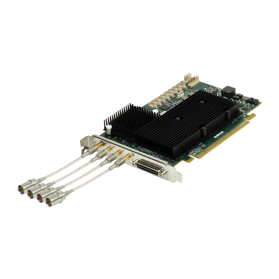
50 Appendix B: Technical information Connectors on Matrox Orion HD boards The Matrox Orion HD board has five interface connectors on its bracket. There are two SDI video output connectors, two SDI video input connectors, and one multi-format input/output connector. -
Page 51: Sdi Video Output Connectors
SMB to BNC cable adapters. The BNC connectors on these adapters are high-quality BNC connectors. The SMB to BNC cable adapters connected to the Matrox Orion HD board and the BNC output connectors on the SMB to BNC cable adapters are shown in the following image. -
Page 52: Sdi Video Input Connectors
SMB to BNC cable adapters. The BNC connectors on these adapters are high-quality BNC connectors. The SMB to BNC cable adapters connected to the Matrox Orion HD board and the BNC input connectors on the SMB to BNC cable adapters are shown in the following image. -
Page 53: Cable Adapter
Windows desktop on a display device. This connector needs to be connected to the Matrox KX20 to 4 DVI-I cable adapter. The Matrox KX20 to 4 DVI-I cable adapter is a high-quality fan-out video cable. It has four DVI-I connectors on one end and a KX20 connector on the other end. - Page 54 54 Appendix B: Technical information DVI-I connectors 1/5 and 2/6 (multi-format output) DVI-I connectors 1/5 and 2/6 are output connectors. A DVI-I connector is shown in the following image: The pin assignment for output DVI-I connectors 1/5 and 2/6 is as follows: P i n S i g n a l D e s c r i p t i o n...
- Page 55 Connectors on Matrox Orion HD boards DVI-I connectors 3/7 and 4/8 (multi-format input) DVI-I connectors 3/7 and 4/8 are input connectors. A DVI-I connector is shown in the following image: The pin assignment for input DVI-I connectors 3/7 and 4/8 is as follows:...
- Page 56 56 Appendix B: Technical information...
-
Page 57: Appendix C: Listing Of Matrox Orion Hd Boards
Appendix C: Listing of Appendix C: Matrox Orion HD boards This appendix lists the key feature changes to the Matrox Orion HD board. -
Page 58: Key Feature Changes
58 Appendix C: Listing of Matrox Orion HD boards Key feature changes P a r t n u m b e r V e r s i o n D e s c r i p t i o n... - Page 59 Index connecting display devices DVI-D 25 RGB 26 SDI 24 external devices 23 acquisition video sources features 9 CVBS 28 video formats 9 DVI-D 29 adapter RGB 28 DVI to VGA 16 SDI 27 KX20 to 4 DVI-I 15 Y/C 28 –...
- Page 60 KX20 input/output connector 23 KX20 to 4 DVI-I cable adapter 53 electrical specifications 47 external devices connecting 23 – LEDs 11 limitations – Matrox Orion HD board 11 frame defined 38 – global information 44 defined 38 grab defined 38...
- Page 61 50 DVI-I 54 contents 15 multi-format 54 data transfer 11 SDI 51 dimensions 47 precautions display features 10 Matrox Orion HD 21 electrical specifications 47 – limitations 11 major revisions 58 memory 11 requirements overview 8 computer 14 precautions 21...
- Page 62 standard definition defined 40 static electricity draining 16 support technical 17 – technical specifications 44 transmitter defined 40 multi-format 10 vertical synchronization defined 40 defined 40 to DVI adapter 16 video sources connecting CVBS 28 DVI-D 29 RGB 28 SDI 27 Y/C 28 YPbPr 28 formats supported 9...
-
Page 63: Fcc Compliance Statement
Regulatory Compliance FCC Compliance Statement Warning Changes or modifications to these units not expressly approved by the party responsible for the compliance could void the user's authority to operate this equipment. The use of shielded cables for connections of these devices to other peripherals is required to meet the regulatory requirements. - Page 64 Bitte wenden Sie sich an dem Matrox-Website (www.matrox.com/environment/weee) für Recycling Informationen. (Italiano) Informazioni per gli utenti europei – Direttiva sui rifiuti di apparecchiature elettriche ed elettroniche (RAEE) Si prega di riferirsi al sito Web Matrox (www.matrox.com/environment/weee) per le informazioni di riciclaggio.
-
Page 65: Limited Warranty
Software Package provided by Matrox is not covered under this limited warranty. 1.3 Matrox's limited warranty covers only those defects which arise as a result of normal use of the Matrox Hardware and does not apply to any damage which arises from: i) improper or inadequate maintenance;... - Page 66 (including theft); 1.4 If Matrox receives from the Licensee, during the applicable warranty period, notice of a defect in the Matrox Hardware, which is subsequently confirmed by Matrox, Matrox shall at its sole option, either i) repair the defect using new or refurbished parts and return the repaired Matrox Hardware within a reasonable delay;...
- Page 67 Matrox Hardware. 1.13 If the Purchaser needs to return Matrox Hardware, it must pack the Matrox Product in its original box and return it to its Matrox dealer where the Matrox Product was purchased, together with the proof of purchase. The Matrox dealer will return the Matrox Product for the Purchaser.
Need help?
Do you have a question about the orion HD and is the answer not in the manual?
Questions and answers