Table of Contents
Advertisement
Quick Links
2016 Lennox Industries Inc.
©
Dallas, Texas, USA
Table of Contents
General ...........................................................................1
Included Parts.................................................................2
Model Number Identification ...........................................3
Indoor / Outdoor Unit Match-Ups....................................4
Typical System Components ..........................................5
System Dimensions ........................................................6
Outdoor Units................................................................6
Indoor Units ..................................................................7
System Clearances ........................................................9
Outdoor Unit .................................................................9
Indoor Unit ....................................................................9
Torque Requirements for Caps and Fasteners.............10
Indoor Unit Installation ..................................................10
Unit Placement Considerations ..................................10
Installation of Cassette Base ......................................10
Installation of M33 Cassette Cover Panel...................11
Indoor Unit Condensate Piping Connections ..............13
Outdoor Unit Installation ...............................................13
Placement Considerations ..........................................13
Direct Sunlight, Rain, Snow and Ice Protection ..........14
Prevailing Winds .........................................................15
Buried Refrigerant Pipe Protection .............................15
Outdoor Unit Condensate Piping ................................15
Securing the Outdoor Unit ..........................................16
Refrigerant Piping Connections ....................................17
Leak Test and Evacuation ............................................18
Leak Test ....................................................................18
Triple Evacuation Procedure .......................................18
Wiring Connections ......................................................19
Outdoor Unit ..............................................................19
Indoor Unit ..................................................................19
Unit Start-Up .................................................................27
Adding Refrigerant for Longer Line Set ........................27
Troubleshooting ............................................................28
Test Run .......................................................................28
Pre-Checks .................................................................28
Procedure ...................................................................28
Dry Mode Operation (Dehumidification) .......................28
Procedure ...................................................................28
Sequence of Operation ...............................................28
INSTALLATION
INSTRUCTIONS
MLA/MPA/MPB and
M22A/M33A/M33B Series
SINGLE-ZONE MINI-SPLIT SYSTEMS
(208/230V) --
Cassette-Mounted Indoor Unit
507546-06
10/2017
Supersedes 10/2016
THIS MANUAL MUST BE LEFT WITH THE OWNER
FOR FUTURE REFERENCE
WARNING
Improper installation, adjustment, alteration, ser vice or
maintenance can cause property damage, personal
injury or loss of life.
Installation and service must be performed by a li censed
professional HVAC installer (or equivalent) or a service
agency.
WARNING
The clean Air Act of 1990 bans the intentional venting of
refrigerant (CFCs, HCFCs, and HFCs) as of July, 1992.
Approved methods of recovery, recycling or reclaiming
must be followed. Fines and/or incarceration may be
levied for non-compliance.
WARNING
This product contains a chemical known to the State
of California to cause cancer, birth defects, or other
reproductive harm.
CAUTION
As with any mechanical equipment, contact with sharp
sheet metal edges can result in personal injury. Take
care while handling this equipment and wear gloves and
protective clothing.
General
Refer to the Product Specifications bulletin (EHB) for more
product information.
These instructions are intended as a general guide and
do not supersede local or national codes in any way.
Authorities having jurisdiction should be consulted before
installation.
The M22A, M33A and M33B ceiling cassette indoor units
are matched with an outdoor heat pump unit to create a
mini-split system that uses HFC-410A refrigerant.
Advertisement
Table of Contents

Related Manuals for Lennox MPA012S4S-1P


Summary of Contents for Lennox MPA012S4S-1P
-
Page 1: Table Of Contents
INSTALLATION INSTRUCTIONS 2016 Lennox Industries Inc. © MLA/MPA/MPB and Dallas, Texas, USA M22A/M33A/M33B Series SINGLE-ZONE MINI-SPLIT SYSTEMS (208/230V) -- Cassette-Mounted Indoor Unit 507546-06 10/2017 Supersedes 10/2016 Table of Contents THIS MANUAL MUST BE LEFT WITH THE OWNER General ................1 FOR FUTURE REFERENCE Included Parts..............2... -
Page 2: Included Parts
Included Parts Package 1 of 1 contains the following: 1 - Assembled Indoor Unit The assembled indoor unit will include the following items: Parts Figure Quantity Parts Figure Quantity M0STAT60Q-1 Installation and owner’s 1 ea. Wireless controller manual Wireless control Paper template for holder with 2 installation... -
Page 3: Model Number Identification
Model Number Identification CASSETTE NON-DUCTED INDOOR UNITS M 22 A 012 S 4 - 1 P Series Type Voltage M = Mini-Split P = 208/230V-1 phase-60hz Unit Type Minor Design Sequence 22 = 2x2 Cassette Non-Ducted Unit 1 = 1st Revision 33 = 3x3 Cassette Non-Ducted Unit 2 = 2nd Revision Major Design Sequence... -
Page 4: Indoor / Outdoor Unit Match-Ups
Indoor / Outdoor Unit Match-Ups Outdoor Unit Indoor Unit Match-Up Voltage MPA009S4S-*P M22A009S4-*P 208/230V MPA012S4S-*P M22A012S4-*P 208/230V MPA018S4S-*P M22A018S4-*P 208/230V MPA024S4S-*P M33A024S4-*P 208/230V MPA036S4S-*P M33A036S4-*P 208/230V MPA048S4S-*P M33A048S4-*P 208/230V MPB009S4S-*P M22A009S4-*P 208/230V MPB012S4S-*P M22A012S4-*P 208/230V MPB018S4S-*P M22A018S4-*P 208/230V MPB024S4S-*P M33A024S4-*P 208/230V MPB036S4S-*P M33A036S4-*P... -
Page 5: Typical System Components
Typical System Components MPORTANT - Condensate drain line must always be located at the bottom of the bundle.) Line set (wrapped in foam insulation) Wiring Communication cable 036 and 048 only Tape Indoor unit wiring connections Condensate drain line (under access plate) (wrapped in foam insulation) Indoor Unit Refrigerant Line Set, Condensate Line... -
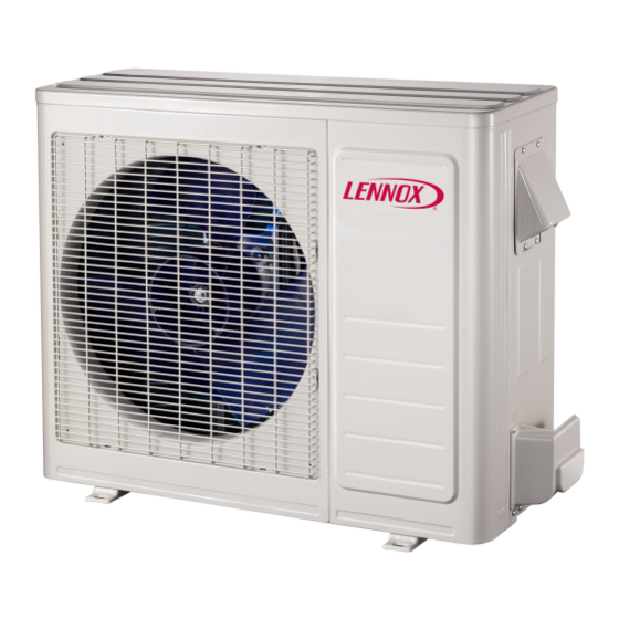
Page 6: System Dimensions
System Dimensions Outdoor Units Table 1. Outdoor Unit Dimensions - Inches (mm) TYPICAL APPEARANCE OF UNITS Unit of Model Measurement inches 33-1/4 21-5/8 11-3/8 12-3/4 MPA009S4S-*P MPA012S4S-*P inches 36-1/8 27-1/2 12-3/4 MPA018S4S-*P inches 40-5/8 25-1/4 31-7/8 15-1/8 MPA024S4S-*P MPA036S4S-*P 1032 inches 40-1/4 53-3/4... -
Page 7: Indoor Units
Indoor Units DRAIN CONNECTION PIPE LIQUID PIPE SIDE VIEW 10-3/8 (264) 22-1/2 20-5/8 (572) (524) Fresh Air Intake (NOTE - Not Used) LEFT SIDE VIEW RIGHT SIDE VIEW 21-1/2 (546) 22-1/2 (572) BOTTOM VIEW (Body) INSTALLATION HANGERS LEVELING ADJUSTMENT NUT (4) CEILING OUTLET OUTLET... - Page 8 PIPE LIQUID PIPE 30-3/4 (781) 33-1/8 (841) Fresh Air Intake (NOTE - Not Used) DRAIN CONNECTION LEFT SIDE VIEW RIGHT SIDE VIEW 26-3/4 (679) 33-1/8 (841) Size BOTTOM VIEW (Body) 8-1/8 9-5/8 11-1/4 OUTLET OUTLET DIFFUSER INLET PANEL SIDE VIEW 37-3/8 (949) 37-3/8 (949)
-
Page 9: System Clearances
System Clearances Outdoor Unit 24 (610) Air Inlet (305) (305) (610) (2007) Air Outlet Minimum rear clearance can be 6 inches (152 mm) when mounted on brackets and with no obstructions on the other three sides. Figure 4. Outdoor Unit Clearances - inches (mm) Indoor Unit 36”... -
Page 10: Torque Requirements For Caps And Fasteners
See the Lennox Service and Application Notes C-08-1 for further details and information. Installation of Cassette Base It is important to place the cassette unit in the center of the Table 1. -
Page 11: Installation Of M33 Cassette Cover Panel
Unistrut channel fixed securely in place to accept the Installation of M33 Cassette Cover Panel ⅜” threaded rods. IMPORTANT 5. Slide one nut and one washer onto each threaded rod. Use electrical tape to keep the washer from failing off. Do not place the cover panel with the diffusers face down Position the nuts slightly above the final resting place on the floor or other surface. - Page 12 to make sure that the panel is properly aligned with the CASSETTE BASE REFRIGERANT cassette base. PANEL HOOK PIPING CONNECTIONS HANGER CONDENSATE ⅜” DRAIN THREADED CONNECTION DETAIL A ≥7/8 (22 mm) LEVELING DETAIL B 1-7/8 (48 mm) CEILING CASSETTE COVER PANEL UNIT BASE DETAIL C FOAM...
-
Page 13: Indoor Unit Condensate Piping Connections
Indoor Unit Condensate Piping Connections IMPORTANT 7-7/8in. 2~3-15/16 in. 3 ft. (1 m) Make sure that drain piping is properly routed and insulated to prevent both leaks and condensation. Cassette SUPPORT Unit 1. Use a field-provided hose clamp to secure the drain STRAPS line stub on the side of the cabinet to a field-supplied Drain... -
Page 14: Direct Sunlight, Rain, Snow And Ice Protection
• There must be sufficient space to carry the unit into Protective canopy and out of the site Protective canopy • There must be unobstructed air flow around the air in- let and the air outlet • The unit must not be installed in areas where a flam- mable gas leak may occur 24 in 610 mm... -
Page 15: Prevailing Winds
24 in 610 mm 24 in 12 in 610 mm 305 mm 12 in 305 mm NOTE - Minimum clearances shown. Figure 19. Avoid Defrost Water Ice Hazard Figure 21. Dog House-Style Shelter Prevailing Winds Normally wind baffles are not required for a outdoor unit. However, in order to maximize reliability and performance, the following best practices should be followed. -
Page 16: Securing The Outdoor Unit
rubber plugs to cover any unused drain holes (see “Figure 23. Condensate Drain” on page 16). Four Field-Provided Anchor Bolts Figure 25. Securing Outdoor Unit to Rails Securing Outdoor Unit to Hanging Brackets If the outdoor unit is installed on field-provided wall mounting brackets, use lag bolts or equivalent to secure Condensate Drain Drain... -
Page 17: Refrigerant Piping Connections
Refrigerant Piping Connections Table 2. Refrigerant Piping and Indoor Unit Connection Sizes Field piping consists of two copper lines connecting the Size Liquid Line Gas Line outdoor unit to the indoor unit. “Table 2. Refrigerant Piping (Btuh) and Indoor Unit Connection Sizes”lists the connection 9000 sizes. -
Page 18: Leak Test And Evacuation
Table 4. Refrigerant Line Set Requirements Minimum Line Set Length - 10 ft. (3m) Maximum Line Set OUTDOOR UNIT INDOOR UNIT Length Maximum Line Set Length Maximum Maximum Elevation - Elevation - INDOOR UNIT Outdooor Outdooor Unit BELOW Unit ABOVE Indoor Unit Indoor Unit OUTDOOR UNIT... -
Page 19: Wiring Connections
Triple Evacuation Procedure • Refer to unit nameplate for minimum circuit ampacity and maximum over-current protection size A Micron or Torr gauge must be used for this procedure. • Make all electrical power wiring connections at the out- 1. Discharge the oxygen-free nitrogen and evacuate the door unit system to a reading of 8000 Microns (8 Torr) using all service valves. - Page 20 Indoor Unit CommunicationTerminal Block 208/230V Outdoor Unit 208/230V Outdoor Unit Power Terminal Block Power Terminal Block L1 L2 L1 L2 208/230V Indoor Unit Power Terminal Block L1 L2 From Power Suppl y Outdoor Unit Communication Terminal Block S1 S2 Indoor Unit Outdoor Unit Figure 30.
- Page 21 INDOOR UNIT MAIN BOARD CN 15 CN13 Note1:remove the JR6 jumper for PUMP remote on/off control CN40 Remote PROGRAMMABLE Control WIRED CONTROLLER Alarm Output DISPLAY TO WIR E CN10(CN10A) CON TRO LLE R BOARD INDOOR COIL OUTLET TEMP.SENSOR INDO OR C OIL T EMP .SENS OR BLACK Q E P ROO M T EMP .SEN SOR...
-
Page 22: Control Board
OUT DOOR CN414 CRANKCASE HEATER CN15 L-OUT BLUE CN13 CN12 BLUE OUTDOOR CN14 MAIN BLACK YELLOW CN6-1 CN10 COMPRESSOR OUTDOOR COIL COMPRESSOR OUTDOOR TEMP.SENSOR TEMP. TEMP.SENSOR Figure 34. 208/230V MPA018S4S-*P Outdoor Unit Wiring Diagram Compressor L-OUT COMPRESSOR DISCHARGE Control Board TEMP.SENSOR CN10 YELLOW... - Page 23 BLACK COMP BLUE COMPRESSOR DISCHARGE TEMP. SENSOR CODE PART NAME COMP COMPRESSOR CN34 CN12 CN11 CN20 ELECTRIC EXPANSION VALVE 4 WAY OUTDOOR DC FAN VALVE BLACK CRANKCASE HEATER HEAT1 ORANGE PAN HEATER HEAT2 DRIVER BOARD CN33 BLUE H-PRO HIGH PRESSURE SWITCH HEAT1 CN10 BLACK...
- Page 24 BLACK BLUE BLUE BROWN CN 1A OUTDOOR BLUE MAIN 4-WAY VALVE BLACK CRANKCASE HEATER COMPRESSOR HEATER CN 21 CN 7 CN 31 OUTDOOR Figure 38. 208/230V MPB009S4S-*P and MPB012S4S-*P Outdoor Unit Wiring Diagram COMPRESSOR (T5) (T3) (T4) Figure 39. 208/230V MPB018S4S-*P and MPB024S4S-*P Outdoor Unit Wiring Diagram...
- Page 25 BLACK CO MP FM 1 BLUE CN20 CN34 4-WAY VALVE BLUE BLACK BLUE CN22 DRIVER BOARD CN33 BLUE BLACK HEAT1 BLA CK CN54 CN40 BLUE CN51 BLACK CN10 HEAT2 BLACK CN53 CN44 BLUE CN52 H-P R O BLACK L-P R O YELLOW YELLOW C ODE...
- Page 26 YELLOW YELLOW PAR T N AME C ODE C OMP C OMP R E S S OR C T 1 AC CURRENT DETECTOR DIO DE MODULE E LE C T R IC E XPANS IO N E XV VALV E FM1,FM2 OUTDOOR DC FAN HE AT 1...
-
Page 27: Unit Start-Up
BLACK COMP BLUE BLACK CN33 CN20 BLUE YELLOW 4-WAY1 CN54 BLUE BLACK BLUE BLUE CN51 HEAT1 CN53 CN10 Crankcase Heater BLUE CN22 CN52 CN40 HEAT2 CN44 Base Pan Heater YELLOW YELLOW H-PRO CODE PART NAME BLACK L-PRO COMP COMPRESSOR CAP1 FAN MOTOR CAPACITOR ELECTRIC EXPANSION VALVE... -
Page 28: Troubleshooting
4. Let each function run for 5 minutes, and perform the Troubleshooting following checks: Table 7. Troubleshooting Codes Table 8. Test Run Checklist Code Description Checks Pass Fail Indoor unit EEPROM error No electrical leakage Communication error between indoor unit and outdoor unit Unit is properly grounded Indoor fan speed error All electrical terminals...
Need help?
Do you have a question about the MPA012S4S-1P and is the answer not in the manual?
Questions and answers