Table of Contents
Advertisement
2017 Lennox Industries Inc.
©
Dallas, Texas, USA
Table of Contents
General ...........................................................................1
Included Parts.................................................................2
Model Number Identification ...........................................3
Indoor / Outdoor Unit Match-Ups....................................4
Typical System Components ..........................................5
System Dimensions ........................................................6
Outdoor Units ..............................................................6
Indoor Units .................................................................7
System Clearances ........................................................8
Outdoor Unit ................................................................8
Indoor Unit ...................................................................8
Torque Requirements for Caps and Fasteners...............9
Indoor Unit Installation ....................................................9
Unit Placement Considerations ...................................9
Determining Wall Mounting Plate Location ..................9
Installation of Wall Mounting Plate...............................9
Installation of Wall Sleeve..........................................10
Indoor Unit Condensate Piping Connections .............12
Outdoor Unit Installation ...............................................12
Placement Considerations .........................................12
Direct Sunlight, Rain, Snow and Ice Protection .........13
Prevailing Winds ........................................................14
Buried Refrigerant Pipe Protection ............................14
Outdoor Unit Condensate Piping ...............................14
Securing the Outdoor Unit .........................................15
Refrigerant Piping Connections ....................................15
Leak Test and Evacuation ............................................18
Leak Test ...................................................................18
Triple Evacuation Procedure......................................18
Wiring Connections ......................................................18
Outdoor Unit .............................................................18
Indoor Unit .................................................................18
Unit Start-Up .................................................................26
Adding Refrigerant for Longer Line Set ........................26
Troubleshooting ............................................................26
Test Run .......................................................................26
Pre-Checks ................................................................26
Procedure ..................................................................26
Double-Check Pipe Connections ...............................27
If Ambient Temperature is below 63°F (17°C) ...........27
Dry Mode Operation (Dehumidification) .......................27
Procedure ..................................................................27
Sequence of Operation ..............................................27
INSTALLATION
INSTRUCTIONS
MLA/MPA/MPB and
MWMA/MWMB Series
SINGLE-ZONE MINI-SPLIT SYSTEMS
(115V and 208/230V) --
Wall-Mounted Indoor Unit
507545-06
4/2017
Supersedes 10/2016
THIS MANUAL MUST BE LEFT WITH THE OWNER
FOR FUTURE REFERENCE
WARNING
Improper installation, adjustment, alteration, ser vice or
maintenance can cause property damage, personal
injury or loss of life.
Installation and service must be performed by a li censed
professional HVAC installer (or equivalent) or a service
agency.
WARNING
The clean Air Act of 1990 bans the intentional venting of
refrigerant (CFCs, HCFCs, and HFCs) as of July, 1992.
Approved methods of recovery, recycling or reclaiming
must be followed. Fines and/or incarceration may be
levied for non-compliance.
WARNING
This product contains a chemical known to the State
of California to cause cancer, birth defects, or other
reproductive harm.
CAUTION
As with any mechanical equipment, contact with sharp
sheet metal edges can result in personal injury. Take
care while handling this equipment and wear gloves and
protective clothing.
General
These instructions are intended as a general guide and
do not supersede local or national codes in any way.
Authorities having jurisdiction should be consulted before
installation.
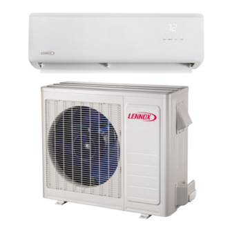
The MWMA and MWMB wall-mounted indoor units are
matched with an outdoor heat pump unit to create a mini-
split system that uses HFC-410A refrigerant.
Advertisement
Table of Contents

Subscribe to Our Youtube Channel
Related Manuals for Lennox MPA009S4S-*L


Summary of Contents for Lennox MPA009S4S-*L
-
Page 1: Table Of Contents
INSTALLATION INSTRUCTIONS 2017 Lennox Industries Inc. © MLA/MPA/MPB and Dallas, Texas, USA MWMA/MWMB Series SINGLE-ZONE MINI-SPLIT SYSTEMS (115V and 208/230V) -- Table of Contents Wall-Mounted Indoor Unit General ................1 507545-06 4/2017 Included Parts..............2 Supersedes 10/2016 Model Number Identification ...........3 Indoor / Outdoor Unit Match-Ups........4 THIS MANUAL MUST BE LEFT WITH THE OWNER Typical System Components ..........5... -
Page 2: Included Parts
Included Parts Package 1 of 1 contains the following: 1 - Assembled Indoor Unit The assembled indoor unit will include the following items: Parts Figure Quantity Parts Figure Quantity M0STAT60Q-1 Installation and owner’s 1 ea. Wireless controller manual Wireless control holder with 2 mounting Mounting plate screws... -
Page 3: Model Number Identification
Model Number Identification OUTDOOR SINGLE ZONE HEAT PUMP UNITS M P A 009 S 4 S - 1 P Series Type Voltage M = Mini-Split L = 115V-1 phase-60hz P = 208/230V-1 phase-60hz Unit Type Minor Design Sequence L = Low Ambient Heat Pump P = Heat Pump 1 = 1st Revision Refrigerant Circuits... -
Page 4: Indoor / Outdoor Unit Match-Ups
Indoor / Outdoor Unit Match-Ups Outdoor Unit Indoor Unit Voltage 115V MPA009S4S-*L MWMA009S4-*L 115V MPA012S4S-*L MWMA012S4-*L 115V MPB009S4S-*L MWMB009S4-*L 115V MPB012S4S-*L MWMB012S4-*L 208/230V MPA009S4S-*P MWMA009S4-*P 208/230V MPA012S4S-*P MWMA012S4-*P 208/230V MPA018S4S-*P MWMA018S4-*P 208/230V MPA024S4S-*P MWMA024S4-*P 208/230V MPA030S4S-*P MWMA030S4-*P 208/230V MPB009S4S-*P MWMA009S4-*P... -
Page 5: Typical System Components
Typical System Components IMPORTANT - Condensate drain line must always be located at the bottom of the bundle.) Line set (wrapped in foam insulation) Wiring Mounting Plate Return Air TAPE Condensate drain line (wrapped in foam insulation) Indoor Unit Refrigerant Line Set, Condensate Line And Indoor / Outdoor Cable (field-provided) Filter... -
Page 6: System Dimensions
System Dimensions Outdoor Units Table 1. Outdoor Unit Dimensions - Inches (mm) TYPICAL APPEARANCE OF UNITS Unit of Model Measurement MPA009S4S-*L inches 33-1/4 21-5/8 11-3/8 12-3/4 MPA009S4S-*P MPA012S4S-*L MPA012S4S-*P inches 36-1/8 27-1/2 12-3/4 MPA018S4S-*P inches 40-5/8 25-1/4 31-7/8 15-1/8 MPA024S4S-*P... -
Page 7: Indoor Units
Indoor Units Table 2. Indoor Unit Dimensions - Inches (mm) Size MWMA009S4S-*L MWMB009S4S-*L MWMA012S4S-*L 32-7/8 29-1/4 7-7/8 MWMB012S4S-*L MWMA009S4S-*P MWMA012S4S-*P MWMA018S4S-*P 12-3/8 34-3/4 8-5/8 MWMA024S4S-*P MWMA030S4S-*P 46-3/4 1187 13-1/2 42-1/2 1080 10-1/4 MWMB030S4S-*P... -
Page 8: System Clearances
System Clearances Outdoor Unit 24 (610) Air Inlet (305) (305) (610) (2007) Air Outlet Minimum rear clearance can be 6 inches (152 mm) when mounted on brackets and with no obstructions on the other three sides. Figure 2. Outdoor Unit Clearances - Inches (mm) Indoor Unit Ceiling 6”... -
Page 9: Torque Requirements For Caps And Fasteners
See the Lennox Service and Application Notes C-08-1 for further details and information. Determining Wall Mounting Plate Location Table 1. Torque Requirements... -
Page 10: Installation Of Wall Sleeve
Installation of Indoor Unit on Wall Mounting Plate plate to better secure wall plate. Field-provided anchors/fixings may be required depending on wall 1. A length of field-provided flexible condensate piping construction. Use the appropriate type of anchors should be connected to the drain prior to securing the for the application. - Page 11 MWMA009S4, MWMB009S4, MWMA012S4, MWMB012S4 Indoor unit 4-3/8 outline (111) 5-1/2 (140) 1-3/4 (44) 1-3/4 (44) 32-7/8 (835) Left rear side Right rear side 1-3/8 refrigerant pipe inlet refrigerant pipe inlet (35) 2-1/2 (64) diameter 2-1/2 (64) diameter MWMA018SA Indoor unit 7/8 (22) outline 1-3/4 (45)
-
Page 12: Indoor Unit Condensate Piping Connections
Indoor Unit Condensate Piping Connections Placement Considerations IMPORTANT Consider the following when positioning the unit: • In coastal areas or other places with salty atmosphere of sulfate gas, corrosion may shorten the life of the Make sure that drain piping is properly routed and unit. -
Page 13: Direct Sunlight, Rain, Snow And Ice Protection
Direct Sunlight, Rain, Snow and Ice Protection • If the outdoor unit is subjected to prolong exposure to direct sunlight with temperatures over 100°F (38°C) a canopy is recommended as illustrated in “Figure 11. Air Inlet Outdoor Unit on Pedestal and Protective Canopy” or “Figure 16. -
Page 14: Prevailing Winds
Prevailing Winds Normally wind baffles are not required for a outdoor unit. However, in order to maximize reliability and performance, the following best practices should be followed. If unit coil cannot be installed away from prevailing winter winds, some method of protecting the coil is recommended. 24 in However, minimum clearances as reference in “Figure 2. -
Page 15: Securing The Outdoor Unit
Securing the Outdoor Unit Slab or Roof Mounting Install the unit a minimum of 4 inches (102 mm) above the roof or ground surface to avoid ice build-up around the 6 in 152 mm unit. Place the unit above a load bearing wall or area of Air Inlet the roof that can adequately support the unit. - Page 16 7. Align threaded connections with Table 3. Flare Nut Torque Recommendations flared refrigerant lines. Tighten the flare nuts lightly at first to obtain a smooth match as No torque wrench available Outside illustrated “Figure Making Connections Recommended Finger tighten and use an Diameter (Male to Female Connection)”.
- Page 17 Table 4. Refrigerant Line Set Requirements Minimum Line Set Length - 10 ft. (3m) Maximum Line Set OUTDOOR UNIT INDOOR UNIT Length Maximum Line Set Length Maximum Maximum Elevation - Elevation - INDOOR UNIT Outdooor Outdooor Unit BELOW Unit ABOVE Indoor Unit Indoor Unit OUTDOOR UNIT...
-
Page 18: Leak Test And Evacuation
4. Break the vacuum by allowing nitrogen into the port Leak Test and Evacuation connections (liquid and gas line pipes) until a positive pressure is achieved Air and moisture remaining in the refrigerant system will 5. Evacuate the system to a minimum reading of 500 have undesirable effects as indicated below: Microns (0.5 Torr). - Page 19 208/230V Indoor Unit 208/230V Outdoor Unit Terminal Block Terminal Block L1 L2 From Power Suppl y Outdoor Unit Indoor Unit NOTE - Use minimum of 18 GA stranded wiring. Figure 24. Single Zone Wiring IMPORTANT This unit must be properly grounded and protected by a circuit breaker.
- Page 20 Figure 25. MWMA and MWMB Unit Wiring Diagram PAN HEATER CRANKCASE CN34 CN15 HEATER CN33 CN32 CN31 CN28 VALVE CN26 YELLOW BLUE BROWN BLUE L-A(CN37) CN10 POWER SUPPLY BLACK BLACK 115V REACTOR Figure 26. 115V MPA009S4S-*L and MPA012S4S-*L Outdoor Unit Wiring Diagram...
- Page 21 COMPRESSOR CRANKCASE HEATER CN31 CN28 CN29 CN30 CN21 CN22 CN33 HEATER CN26 CN27 CN16 YELLOW BLUE CN32-1 CN9-1 WHITE WHITE DC-FAN REACTOR Figure 27. 208/230V MPA009S4S-*P and MPA012S4S-*P Outdoor Unit Wiring Diagram OUT DOOR CN414 CRANKCASE HEATER CN15 L-OUT BLUE CN13 CN12 BLUE...
-
Page 22: Control Board
Compressor L-OUT COMPRESSOR DISCHARGE Control Board TEMP.SENSOR CN10 YELLOW PAN HEATER CRANK CASE HEATER Figure 29. 208/230V MPA024S4S-*P Outdoor Unit Wiring Diagram BLACK V1.0 2015/5/08 COMP BLUE CODE PART NAME COMPRESSOR DISCHARGE COMPRESSOR COMP TEMP. SENSOR OUTDOOR DC FAN HEAT1 CRANKCASE HEATER CN12 CN11... - Page 23 BLACK REACTOR CN 1A BLUE 4-WAY VALVE OUTDOOR BLACK CRANKCASE MAIN HEATER HEATER CN 21 CN 7 CN 31 OUTDOOR Figure 31. 115V MPB009S4S-*L and MPB012S4S-*L Outdoor Unit Wiring Diagram BLACK BLUE BLUE BROWN CN 1A OUTDOOR BLUE MAIN 4-WAY VALVE BLACK CRANKCASE HEATER...
- Page 24 Figure 33. 208/230V MPB018S4S-*P and MPB024S4S-*P Outdoor Unit Wiring Diagram • • • • • COMPONENT IN DASH LINE IS OPTIONAL OR FIELD WIRING. 4-WAY VALVE Figure 34. 208/230V MPB030S4S-*P, Outdoor Unit Wiring Diagram...
- Page 25 Figure 35. 208/230V MLA009, MLA012 and 018S4S-*P Outdoor Unit Wiring Diagram BLACK COMP BLUE BLACK CN33 CN20 BLUE YELLOW 4-WAY1 CN54 BLUE BLACK BLUE BLUE CN51 HEAT1 CN53 CN10 Crankcase Heater BLUE CN22 CN52 CN40 HEAT2 CN44 Base Pan Heater YELLOW YELLOW H-PRO...
-
Page 26: Unit Start-Up
Unit Start-Up Troubleshooting IMPORTANT Table 7. Troubleshooting Codes Code Description Units should be energized 24 hours before unit start-up Indoor unit EEPROM error to prevent compressor damage as a result of slugging. Communication error between indoor unit and outdoor unit 1. -
Page 27: Double-Check Pipe Connections
Table 8. Test Run Checklist Checks Pass Fail No electrical leakage Unit is properly grounded All electrical terminals properly covered Indoor and outdoor units are solidly installed Manual control All pipe connection points do button not leak Water drains properly from drain hose All piping is properly insulated...
Need help?
Do you have a question about the MPA009S4S-*L and is the answer not in the manual?
Questions and answers
Why does my unit leaks water on the control side of unit.
@Jose Your drain line is probably cracked, disconnected or loose. Possibly the drain pan is cracked.
What turns on the condensate pump on a Lenox MWM A024-2P. Pump is continuously running send manual