Table of Contents
Advertisement
2018 Lennox Industries Inc.
©
Dallas, Texas, USA
Table of Contents
General ...........................................................................1
Included Parts.................................................................2
Indoor / Outdoor Unit Match-Ups....................................2
Model Number Identification ...........................................3
Typical System Components ..........................................4
System Dimensions ........................................................5
Outdoor Units ..............................................................5
Indoor Units .................................................................6
System Clearances ........................................................7
Outdoor Unit ................................................................7
Indoor Unit ...................................................................7
Torque Requirements for Caps and Fasteners...............8
Indoor Unit Installation ....................................................8
Unit Placement Considerations ...................................8
Installation ...................................................................8
Installation Guidelines .................................................9
Field-Relocation of Return Air Filter .............................9
Indoor Unit Condensate Piping Connections .............10
Outdoor Unit Installation ...............................................10
Placement Considerations .........................................11
Direct Sunlight, Rain, Snow and Ice Protection .........11
Prevailing Winds ........................................................12
Buried Refrigerant Pipe Protection ............................12
Condensate Piping ....................................................13
Securing the Outdoor Unit .........................................13
Refrigerant Piping Connections ....................................13
Leak Test and Evacuation ............................................16
Leak Test ...................................................................16
Triple Evacuation Procedure......................................16
Wiring Connections ......................................................16
Outdoor Unit .............................................................16
Indoor Unit .................................................................16
Unit Start-Up .................................................................26
Adding Refrigerant for Longer Line Set ........................26
Troubleshooting ............................................................27
Test Run .......................................................................27
Pre-Checks ................................................................27
Procedure ..................................................................27
Dry Mode Operation (Dehumidification) .......................27
Procedure ..................................................................27
Sequence of Operation ..............................................27
INSTALLATION
INSTRUCTIONS
and MMDA Series
SINGLE-ZONE MINI-SPLIT SYSTEMS
(208/230V) --
Medium-Ducted Indoor Unit
507547-06
1/2018
Supersedes 12/2017
THIS MANUAL MUST BE LEFT WITH THE OWNER
FOR FUTURE REFERENCE
WARNING
Improper installation, adjustment, alteration, ser vice or
maintenance can cause property damage, personal
injury or loss of life.
Installation and service must be performed by a li censed
professional HVAC installer (or equivalent) or a service
agency.
WARNING
The clean Air Act of 1990 bans the intentional venting of
refrigerant (CFCs, HCFCs, and HFCs) as of July, 1992.
Approved methods of recovery, recycling or reclaiming
must be followed. Fines and/or incarceration may be
levied for non-compliance.
WARNING
This product contains a chemical known to the State
of California to cause cancer, birth defects, or other
reproductive harm.
CAUTION
As with any mechanical equipment, contact with sharp
sheet metal edges can result in personal injury. Take
care while handling this equipment and wear gloves and
protective clothing.
General
Refer to the Product Specifications bulletin (EHB) for more
product information.
These instructions are intended as a general guide and
do not supersede local or national codes in any way.
Authorities having jurisdiction should be consulted before
installation.
The MMDA Medium-Static Ducted indoor units are
matched with an outdoor heat pump unit to create a mini-
split system that uses HFC-410A refrigerant.
MLA/MPA/MPB
Advertisement
Table of Contents

Related Manuals for Lennox MPA009S4S-*P


Summary of Contents for Lennox MPA009S4S-*P
-
Page 1: Table Of Contents
INSTALLATION INSTRUCTIONS 2018 Lennox Industries Inc. © MLA/MPA/MPB Dallas, Texas, USA and MMDA Series SINGLE-ZONE MINI-SPLIT SYSTEMS (208/230V) -- Medium-Ducted Indoor Unit 507547-06 1/2018 Supersedes 12/2017 Table of Contents THIS MANUAL MUST BE LEFT WITH THE OWNER General ................1 FOR FUTURE REFERENCE Included Parts..............2... -
Page 2: Included Parts
Figure Quantity Parts Figure Quantity Drain connector Seal ring Indoor / Outdoor Unit Match-Ups Outdoor Unit Indoor Unit Voltage 208/230V MPA009S4S-*P or MPB009S4S-*P MMDA009S4-*P 208/230V MPA012S4S-*P or MPB012S4S-*P MMDA012S4-*P 208/230V MPA018S4S-*P or MPB018S4S-*P MMDA018S4-*P 208/230V MPA024S4S-*P or MPB024S4S-*P MMDA024S4-*P 208/230V... -
Page 3: Model Number Identification
Model Number Identification OUTDOOR SINGLE ZONE HEAT PUMP UNITS M P A 009 S 4 S - 1 P Series Type Voltage M = Mini-Split P = 208/230V-1 phase-60hz Unit Type Minor Design Sequence L = Low Ambient Heat Pump 1 = 1st Revision P = Heat Pump Major Design Sequence... -
Page 4: Typical System Components
Typical System Components MPORTANT - Condensate drain line must always be located at the bottom of the bundle.) Line set (wrapped in foam insulation) Wiring Communication cable 036 and 048 only Indoor unit wiring connections Tape (under access plate) Condensate drain line (wrapped in foam insulation) Refrigerant Line Set, Condensate Line Indoor Unit... -
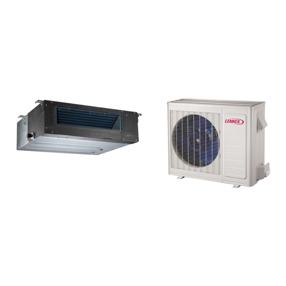
Page 5: System Dimensions
System Dimensions Outdoor Units TYPICAL APPEARANCE OF UNITS Unit of Model Measurement inches 33-1/4 21-5/8 11-3/8 12-3/4 MPA009S4S-*P MPA012S4S-*P inches 36-1/8 27-1/2 12-3/4 MPA018S4S-*P inches 40-5/8 25-1/4 31-7/8 15-1/8 MPA024S4S-*P MPA036S4S-*P 1032 inches 40-1/4 53-3/4 15-3/8 MPA048S4S-*P 1023 1365 inches... -
Page 6: Indoor Units
Indoor Units MOUNTING ELECTRICAL LUGS (4) CONTROL 1 (25) 1 (25) 3/4 (19) 3/4 (19) FRESH AIR INTAKE 3-5/8 (92) Diameter (015 thru 018) 5 (127) Diameter (024 thru 048) TOP VIEW MOUNTING LUGS (4) SUPPLY AIR OPENING LIQUID FRONT VIEW SIDE VIEW PIPE PIPE... -
Page 7: System Clearances
System Clearances Outdoor Unit 24 (610) Air Inlet (305) (305) (610) (2007) Air Outlet Minimum rear clearance can be 6 inches (152 mm) when mounted on brackets and with no obstructions on the other three sides. Figure 4. Outdoor Unit Clearances - Inches (mm) Indoor Unit Wall 20”... -
Page 8: Torque Requirements For Caps And Fasteners
See the Lennox Service and Application Notes C-08-1 the controller for further details and information. Installation Table 1. -
Page 9: Installation Guidelines
4. Use either a mechanical lifting device or a minimum of • Use flexible joints (canvas) at the point where the duct two people to raise the unit and insert the threaded rods connects to the unit on both ends. Material must meet into the suspension brackets on the unit chassis. -
Page 10: Indoor Unit Condensate Piping Connections
Indoor Unit Condensate Piping Connections 4. In all cases, drain should be as short as possible and should not have any droops or kinks that would restrict IMPORTANT condensate flow and shall be constructed using an approved pipe. There must be a 2-inch (51 mm) space Make sure that drain piping is properly routed and between the end of the condensate drain and the final insulated to prevent both leaks and condensation. -
Page 11: Placement Considerations
Placement Considerations opy” or “Figure 20. Dog House-Style Shelter” on page Consider the following when positioning the unit: • In coastal areas or other places with salty atmosphere IMPORTANT of sulfate gas, corrosion may shorten the life of the unit. In coastal areas, the coil should be cleaned with The construction of a canopy or shade is necessary potable water several times per year to avoid corrosive because of an ambient limit control set to 122°F (50°C) -
Page 12: Prevailing Winds
Prevailing Winter Winds from Air Inlet Side Wind Barrier Inlet Air 12” (305mm) Min. Distance 12 in 305 mm 79 in 2007 mm Air Inlet Air Outlet 79” (2007mm) Min. Distance Discharge Air Wind Barrier Prevailing Winter Winds From Air Discharge Side Figure 17. -
Page 13: Condensate Piping
Condensate Piping Condensate formed during the heating and defrost processes must be drained from heat pump units. Drain holes are provided in the base of the units to ensure proper drainage. Heat pumps must be raised when installed on a concrete pad or the ground to allow drainage to occur. - Page 14 2. Confirm that you are using the correct diameter piping. 13. Slide the flare nuts onto the ends of the field-provided refrigerant piping before using a suitable flaring tool to 3. Determine the necessary piping length required for the flare the end of the copper pipe. application.
- Page 15 Table 4. Flare Nut Torque Recommendations and Tightening Procedure IMPORTANT Outside No torque wrench available Diameter Recommended Always use two wrenches when tightening flare Finger tighten and use an appropriately sized Torque nuts to avoid twisting refrigerant piping. DO NOT wrench to turn an additional: Inches over-tighten flare nuts.
-
Page 16: Leak Test And Evacuation
4. Break the vacuum by allowing nitrogen into the port Leak Test and Evacuation connections (liquid and gas line pipes) until a positive pressure is achieved Air and moisture remaining in the refrigerant system will 5. Evacuate the system to a minimum reading of 500 have undesirable effects as indicated below: Microns (0.5 Torr). - Page 17 IMPORTANT This unit must be properly grounded and protected by a circuit breaker. The ground wire for the unit must not be connected to a gas or water pipe, a lightning conductor or a telephone ground wire. Do not connect power wires to the outdoor unit until all other wiring and piping connections have been completed. Do not install the unit near a lighting appliance that includes a ballast.
- Page 18 Table 7. Single Zone Installation Wiring Requirements System and Terminal Number of System Capacity System Voltage Wire Type Wire Gauge / MCA Designations Conductors Indoor to Outdoor Wiring Stranded and (Communication/ 09K and 12K 208/230VAC 16AWG unshielded Power) 1, 2, 3 and GND Outdoor to Main Power Stranded and 09K and 12K...
- Page 19 Alarm Remote • • • • • Output Control COMPONENT IN DASH LINE IS OPTIONAL OR FIELD WIRING. CN1 3 Note: The programmable wired controller RE D CN 8 ALA RM ON/ OFF and regular wired controller CN 18 use the same CN1 5 wiring connector CN3 3...
- Page 20 Figure 32. MMDA036S4-*P & MMDA048SA-*P Ducted Units Wiring Diagram COMPRESSOR CRANKCASE HEATER CN31 CN28 CN29 CN30 CN21 CN22 CN33 HEATER CN26 CN27 CN16 YELLOW BLUE CN32-1 CN9-1 WHITE WHITE DC-FAN REACTOR Figure 33. 208/230V MPA009S4S-*P and MPA012S4S-*P Outdoor Unit Wiring Diagram...
-
Page 21: Control Board
OUT DOOR CN414 CRANKCASE HEATER CN15 L-OUT BLUE CN13 CN12 BLUE OUTDOOR CN14 MAIN BLACK YELLOW CN6-1 CN10 COMPRESSOR OUTDOOR COIL COMPRESSOR OUTDOOR TEMP.SENSOR TEMP. TEMP.SENSOR Figure 34. 208/230V MPA018S4S-*P Outdoor Unit Wiring Diagram Compressor L-OUT COMPRESSOR DISCHARGE Control Board TEMP.SENSOR CN10 YELLOW... - Page 22 BLACK COMP BLUE COMPRESSOR DISCHARGE TEMP. SENSOR CODE PART NAME COMP COMPRESSOR CN34 CN12 CN11 CN20 ELECTRIC EXPANSION VALVE 4 WAY OUTDOOR DC FAN VALVE BLACK CRANKCASE HEATER HEAT1 ORANGE PAN HEATER HEAT2 DRIVER BOARD CN33 BLUE H-PRO HIGH PRESSURE SWITCH HEAT1 CN10 BLACK...
- Page 23 BLACK BLUE BLUE BROWN CN 1A OUTDOOR BLUE MAIN 4-WAY VALVE BLACK CRANKCASE HEATER COMPRESSOR HEATER CN 21 CN 7 CN 31 OUTDOOR Figure 38. 208/230V MPB009S4S-*P and MPB012S4S-*P Outdoor Unit Wiring Diagram COMPRESSOR (T5) (T3) (T4) Figure 39. 208/230V MPB018S4S-*P and MPB024S4S-*P Outdoor Unit Wiring Diagram...
- Page 24 BLACK CO MP FM 1 BLUE CN34 CN20 4-WAY VALVE BLUE BLACK BLUE CN22 DRIVER BOARD CN33 BLUE BLACK HEAT1 BLA CK CN54 CN40 BLUE CN51 BLACK CN10 HEAT2 BLACK CN44 CN53 BLUE CN52 H-P R O BLACK L-P R O YELLOW YELLOW C ODE...
- Page 25 YELLOW YELLOW PAR T N AME C ODE C OMP C OMP R E S S OR C T 1 AC CURRENT DETECTOR DIO DE MODULE E LE C T R IC E XPANS IO N E XV VALV E FM1,FM2 OUTDOOR DC FAN HE AT 1...
-
Page 26: Unit Start-Up
BLACK COMP BLUE BLACK CN33 CN20 BLUE YELLOW 4-WAY1 CN54 BLUE BLACK BLUE BLUE CN51 HEAT1 CN53 CN10 Crankcase Heater BLUE CN22 CN52 CN40 HEAT2 CN44 Base Pan Heater YELLOW YELLOW H-PRO CODE PART NAME BLACK L-PRO COMPRESSOR COMP CAP1 FAN MOTOR CAPACITOR ELECTRIC EXPANSION VALVE... -
Page 27: Troubleshooting
Troubleshooting Table 8. Test Run Checklist Checks Pass Fail Table 9. Indoor Unit Troubleshooting Codes No electrical leakage Display Description Unit is properly grounded Indoor unit EEPROM error All electrical terminals properly covered Communication error between indoor and outdoor units (E2 for outdoor code) Indoor and outdoor units are solidly installed...
Need help?
Do you have a question about the MPA009S4S-*P and is the answer not in the manual?
Questions and answers