Table of Contents
Advertisement
Quick Links
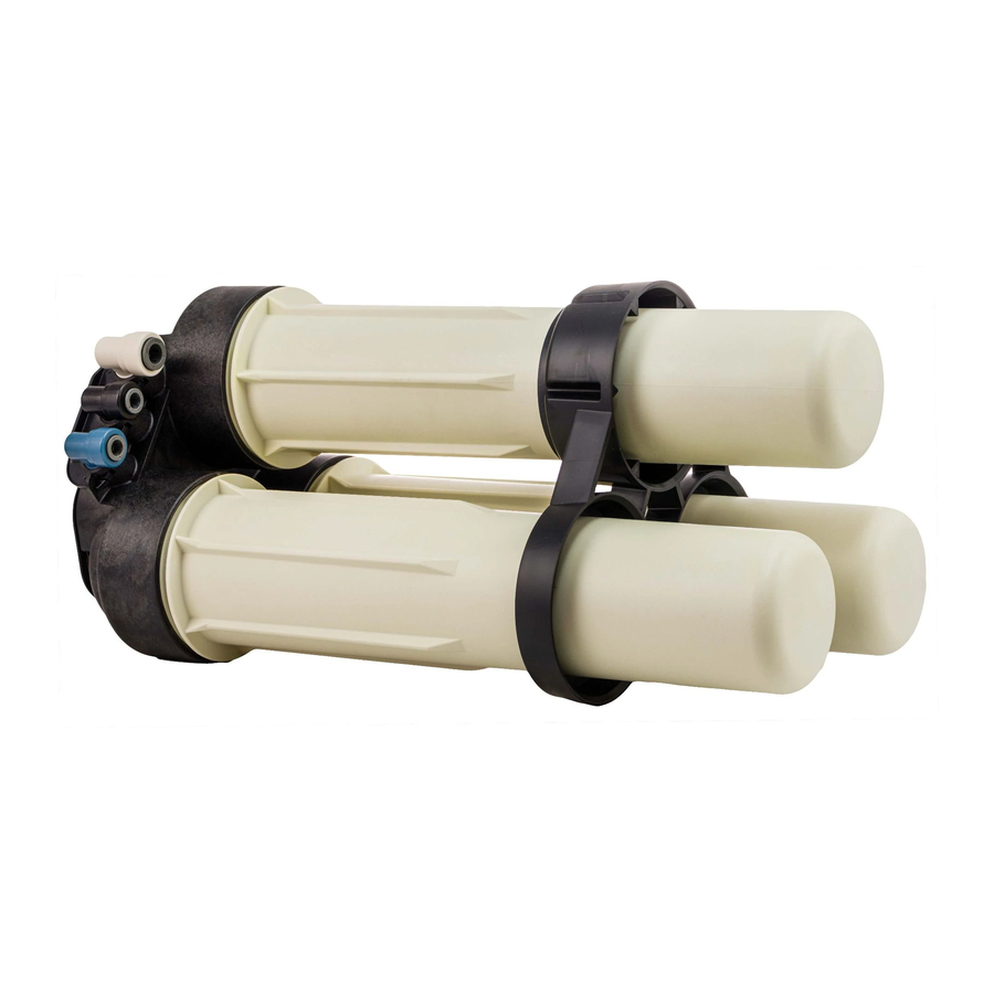
PRF-RO
Pentair Reverse Osmosis System
Installation and Maintenance Manual
SAFETY GUIDES
Read and follow all steps and guides carefully before installing and
using your reverse osmosis system.
Do not use this product to make safe drinking water from non-potable
water sources. Do not use the system on microbiologically unsafe
water, or water of unknown quality without adequate disinfection
before or after the system.
This reverse osmosis system contains replaceable components
(membrane elements). These components are critical for the
effective reduction of total dissolved solids and specific contaminants
that are listed in the Product Data Sheet.
The Reverse Osmosis System does not have a monitoring device for
contaminants. To verify that the system is performing satisfactorily
the product water should be tested periodically by the system's
installing dealer or a certified laboratory, every six months. The
laboratory should be certified for testing the specific contaminants of
concern. For a listing of certified laboratories, contact local regulatory
agencies. Within the United States, many state-run Department of
Natural Resources or Department of Health Services maintain listings
of certified laboratories.
Consult your local public works department for plumbing and
sanitation codes. Follow your local codes if they differ from this
manual.
The reverse osmosis system works on water pressures of 40 psi
(2.8 bar) minimum to 80 psi (5.5 bar) maximum. Water pressure can
be reduced by installing a pressure reducing valve in the water
supply pipe to the RO system. A booster pump should be used for low
pressure applications.
Do not install the reverse osmosis system in extreme hot or cold
temperatures. Temperature of the water supply to the reverse
osmosis system must be between 40°F (4°C) and 100°F (38°C). Do not
install on hot water lines.
The reverse osmosis membranes contain a foodgrade preservative
for storage and shipment. All new membranes require a minimum 2
hour rinse to properly rinse out the preservative. The preservative
is not harmful but makes the product water taste objectionable.
Rinsing the membrane also acts a performance conditioner. All new
membranes will reach their stable maximum performance after 8
hours of rinsing.
THE BASIC REVERSE OSMOSIS SYSTEM
Your Reverse Osmosis System is a water treatment unit. It uses water
pressure to reverse a natural physical process called osmosis. Water,
under pressure, is forced through a semi-permeable membrane to
filter out minerals and impurities. Treated drinking water goes to the
faucet. Minerals and impurities are sent to the drain with RO waste
water.
The system includes replaceable filters and membrane elements. The
prefilter reduces sand, silt, dirt, rust particles, other sediments, and
chlorine from the water supply before they enter the RO membrane
elements. The postfilter reduces any tastes and/or odors that
may remain in the water after passing through the RO membrane
elements.
BEFORE INSTALLING THE RO SYSTEM
• Best performance of the system will be achieved when the
incoming water has been treated (softened).
• The water coming into the system must be within certain limits
for sediments, pressure, etc. Refer to the specifications to
determine if your installation is within the limits.
• A water quality analysis can be performed to determine if
incoming water requires any treatment. Contact your dealer/
installer.
• The filters and membrane elements in the RO system need
to be replaced on a regular basis. Follow the instructions for
replacement that are in this manual.
NOTE: For optimal system performance, use the system for at least 2
minutes continuously each day.
The RO system is designed to work without the
WARNING:
aid of a pressurized storage tank. Installation of
a pressurized storage tank will negatively affect
system performance.
Tools and Materials Required
• Adjustable wrench, and larger adjustable jaw pliers or pipe
wrench to fit sink drain
• Saw for cutting drain pipe
• Slotted and Phillips head screwdrivers
• Tubing cutters
• Electric drill and bits for cutting the faucet mounting hole
NOTE: Note that some sinks will have a pre-drilled hole with a
plug for the faucet.
4000413 Rev B
JE10
Advertisement
Table of Contents

Subscribe to Our Youtube Channel
Related Manuals for Pentair PRF-RO


Summary of Contents for Pentair PRF-RO
- Page 1 PRF-RO Pentair Reverse Osmosis System Installation and Maintenance Manual SAFETY GUIDES THE BASIC REVERSE OSMOSIS SYSTEM Read and follow all steps and guides carefully before installing and Your Reverse Osmosis System is a water treatment unit. It uses water using your reverse osmosis system.
- Page 2 THE BASIC REVERSE OSMOSIS SYSTEM cont. SOME CONFIGURATIONS MAY NOT INCLUDE ALL COMPONENTS LISTED BELOW SUPPORT ELEMENT FITTINGS & LOCKING BAR (TFC-350 IND) SUMP INSTALL KIT PN 4000569 & SEAL PN 3038021 (2 pcs) PN 4000330 (1 pc) FEED LOCKING BAR SUMP DISCONNECT DISCONNECT...
- Page 3 THE BASIC REVERSE OSMOSIS SYSTEM cont. LOCATION OF SYSTEM Drain Point: A suitable drain point is needed for reject water from the RO system. A floor drain, laundry tub, standpipe, sump, etc. are The reverse osmosis system is designed for installation under a sink, all acceptable.
- Page 4 THE BASIC REVERSE OSMOSIS SYSTEM cont. Faucet without Air Gap Product - 3/8" Blue Keep to Minimum Floor Carbon Postfilter Feed Water Valve Cold Water Line Only Inlet-1/2" Natural Drain - 3/8" Black RO Assembly 1.5" Air Gap Required Figure 3 Typical Basement Installation...
- Page 5 THE BASIC REVERSE OSMOSIS SYSTEM cont. Feed Pressure Gauge Feed Water Valve Cold Water Line Only Feed Solenoid Valve External Prefilter Inlet-1/2" Natural Drain - 3/8" Black RO Assembly 1.5" Air Gap Required Vented to Atmosphere Liquid level float sensor to control feed solenoid valve To Point of Use Product Storage Tank...
-
Page 6: Installation
INSTALLATION STEP 1: Install cold water supply valve STEP 2: Install drain adapter STEP 3: Install faucet STEP 4: Make tubing connections STEP 5: Install RO assembly STEP 6: Put system into operation NOTE: Consult a licensed plumber if you are not familiar with plumbing procedures. -
Page 7: Step 4: Make Tubing Connections
INSTALLATION cont. Step 4: Make Tubing Connections The connections to the faucet should be complete, the remaining Collet connections are: Lock Clip • Feed connection—clear tubing from feed valve to white elbow connector • Drain connection—either red tubing from the air gap or black tubing from grey elbow connector will attach to the drain adapter • Permeate connection—blue tubing from faucet to blue elbow... - Page 8 INSTALLATION cont. Recommended Placement Positions The RO assembly should be positioned in one of two ways. Support Leg Locking Bar The first position is with the unit standing upright using the support leg with the sumps horizontal. The tubing is directed to provide the best fit.
-
Page 9: Step 6: System Startup
INSTALLATION cont. The table below shows the coding system for the fitting connections. Each fitting has a unique “keyed” socket on the manifold. Each fitting also has a graphic symbol molded into the elbow with a corresponding symbol on the manifold. Connector Symbol Connection Tubing Color... - Page 10 TO CARE FOR THE RO SYSTEM The components of the RO system are designed to function with minimal maintenance. However, the membrane elements and filters will need to be replaced on a regular schedule. For optimal performance the system should be flushed for 2 minutes if periods of inactivity extend past six hours.
- Page 11 REPLACEMENT OF THE PREFILTER, POSTFILTER, AND RO MEMBRANE ELEMENTS cont. e. Replace sumps and tighten until it bottoms out. NOTE: The system should be sanitized whenever a membrane element or filter is replaced. Membrane Element 8. Sanitize the system. Locations a.
-
Page 12: Performance Specifications
Performance Specifications Minimum and Maximum Operating Conditions Condition Minimum Maximum Inlet Pressure 40 psi (2.76 bar) 80 psi (5.52 bar) Inlet Temperature F (4.44 F (37.78 ° ° ° ° Inlet TDS 50 mg/L 2,000 mg/L Inlet Hardness 0 mg/L (0 grain) 171 mg/L (10 grain) Inlet Chlorine 0 mg/L... -
Page 13: Troubleshooting
TROUBLESHOOTING Issue Possible Cause Corrective Action Low product flow rate Low driving pressure. Increase feed pressure. Consider pump for low pressure locations. Use short tubing runs to decrease flow restriction. Increase tubing diameter for longer distances. Low water temperature or high total dissolved solids Increase feed water temperature or feed pressure to compensate. - Page 16 © 2010 Pentair Residential Filtration, LLC 4000413 Rev. B JE10...
Need help?
Do you have a question about the PRF-RO and is the answer not in the manual?
Questions and answers