
Related Manuals for Mac Afric WPLANE-200


Summary of Contents for Mac Afric WPLANE-200
- Page 1 This Manual is Bookmarked 8-inch Professional Jointer Operating Instructions and Parts List...
-
Page 2: Table Of Contents
Table of Contents Table of Contents ............................2 Warning..............................3 Identification ............................5 Specifications ............................5 Unpacking and Cleanup ..........................6 Unpacking and Cleanup ........................6 Installing Bed to Stand .........................7 Installing Handwheels ..........................7 Instakking Fende To Fence Carriage......................8 Installing V-Belts ...................... -
Page 3: Warning
Warning 1. Read and understand the entire owners manual before attempting assembly or operation. 2. Read and understand the warnings posted on the machine and in this manual. Failure to comply with all of these warnings may cause serious injury. 3. - Page 4 21. Make your workshop child proof with padlocks, master switches or by removing starter keys. 22. Give your work undivided attention. Looking around, carrying on a conversation and “horse-play” are careless acts that can result in serious injury. 23. Maintain a balanced stance at all times so that you do not fall or lean against the knives or other moving parts.
-
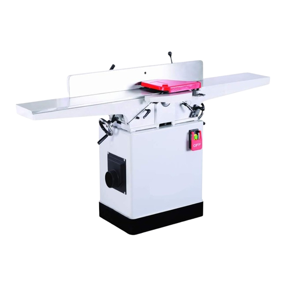
Page 5: Identification
Identification H.Infeed Table Lock A.Outfeed Table I.1/8"Depth Stop B.Infeed Table J.Magnitic Switch C.Fence K.Cutterhead Guard D.Fence Tilt Handle L.Fence Lock E.Outfeed Table Handwheel M.4"Dust Port F.Infeed Table Handwheel G.Outfeed Table Lock Specifications Cutting Capacity ............8"W x 1/2"D ............Cutterhead Speed 5500 RPM Number of Knives..............4 Rabbeting Capacity... -
Page 6: Unpacking And Cleanup
Unpacking and Cleanup Contents of Shipping Cartons Note: Unit shipped in one crate and one carton. Stand Carton(Not shown in picture) Stand with Motor and Switch Jointer Body Crate Jointer-Body Assembly(Not shown) Fence Fence Carriage Assembly Cutterhead Guard Dust Chute Belt Guard Handwheels*2 Handwheel Handles*2... -
Page 7: Installing Bed To Stand
Cutterhead knives dangerously sharp! extreme caution when cleaning. 4. Apply a thin layer of paste wax to the bright surfaces of the fence and tables to prevent rust. Installing Bed to Stand 1. Use an assistant or hoist mechanism to Figure 1 place bed assembly on top of stand. -
Page 8: Instakking Fende To Fence Carriage
Installing Fence Carriage to Jointer 1. Lossen the two cap screws attached on the back of the jointer. Note-DO NOT completely remove the cap screws. 2. Use an man assistant to hold the fence carriage. 3. Line up two open holes on the fence carriage with the two cap screws. -
Page 9: Installing V-Belts
Installing V-Belts 1. Disconnect the machine from the power source, unplug. 2. Remove the lock knob (A, Fig. 4) and belt guard (B, Fig. 4). 3. Place v-belts onto cutterhead pulley grooves and through opening in stand. 4. In stand, lossen the motor mount bolts. Note-DO NOT completely remove the motor mount bolts. -
Page 10: Installing Cutterhead Guard
Installing Cutterhead Guard 1. Wind the tang the torsion spring back a half turn, and slide the guard shaft into the casting so the spring tang points tp the right and reset against the casting.(Fig. 7) 2. Test the guard by pulling in back and letting go. - Page 11 2. Rotate the cutterhead by turning the cutterhead pulley until one of the knives is at top-dead-center(TDC), as shown in Fig.10 3. Loosen table lock screw (A, Fig. 9) and raise the outfeed table to the height of blade number one by turning handwheel (B, Fig. Counter-clockwise will cause...
-
Page 12: Adjustments
Adjustments To Set The 90° Fence Stop Note: whenever making an adjustment to the fence, lift the fence up slightly after releasing the lock handle to avoid scratching the table. ° 1. Using a 90 square, adjust the fence to the °... -
Page 13: Gib Adjustment
To Set the 45° Outward Fence Stop Note: Whenever making an adjustment to the fence, lift the fence up slightly after releasing the lock handle to avoid scratching the table. ° 1. Using a sliding bevel adjusted to 135 , adjust °... -
Page 14: Removing And Replacing Knives
Removing and Replacing Knives (Stright Knife Cutterhead Only) Disconnect the machine from power source before making adjustment or repair. All knife lock bolts must be firmly tightened or risk ejection of the knife(s) and lock bar from the cutterhead! Failure to comply may cause serious injury! 1. -
Page 15: Operation
Each knife insert has an etched reference mark so that you can keep track of the rotations. IMPORTANT: When removing rotating inserts, clean saw dust from the screw, the insert, and the cutterhead platform. Dust accumulation between these elements can prevent the insert from seating properly, and may affect the quality of the cut. -
Page 16: Jointing Warped Material
For jointing and planing cuts pressure is directed three ways; into the fence to ensure a square cut, forward to advance the stock, and downward to avoid chatter and vibration. For jointing when the material is higher than the fence, the left hand applies pressure into the fence and down toward the table while the right hand pushes forward from behind. -
Page 17: Taper Cut
Taper Cut Taper cuts require removal of the cutterhead guard. extreme caution when making taper cuts and replace guard immediately after completion! Failure to comply may cause serious injury! One of the most useful jointer operations is cutting an edge to a taper. This method can be used on a wide variety of work;... -
Page 18: Maintenance
7. Take the same amount of passes for all Maintenance three blades. When the blades have been sharpened, if they Lubrication still are not cutting efficiently, trying to touch up the blades further will only cause the formation 1. Use a good grade of light grease on the of a second beveled edge. -
Page 19: Troubleshooting
6. Lift assembly straight up. Studs (F, Fig. 30) and the bearing housings of saw dust and will still be attached to the bearing housings. grease so that they seat properly. 7. Before replacing the cutterhead back into 8. To re-install the cutterhead, reverse the the casting, thoroughly clean the “saddle”... -
Page 20: Jointer Body Diagram And Part List
JOINTER BODY DIAGRAM AND PARTS LIST ITEM ITEM DESCRIPCTION DESCRIPCTION BASE WASHER - 8 OUTFEED TABLE INFEED TABLE ROLL PIN 4-12MM BRACKET GUARD PIVOT SHAFT HAND WHEEL SHAFT ROLL PIN 6-40 RING ROLL PIN 6-35MM SET SCREW M6-8 CUTTER HEAD GUARD TABLE ADJUST ROD RETURNING RING 12MM CAP SCREW - M10 x 30... -
Page 21: Cutterhead Diagram And Part List
CUTTERHEAD DIAGRAM AND PART LIST ITEM DESCRIPCION CUTTERHEAD BLADE SET SCREW M5*12 BLADE GIB BOLT M6*8 LOCK WASHER 10 STUD WASHER NUT M10 CUTTERHEAD PULLEY KEY 5*30 SET SCREW M5*10 BALL BEARING 6204 BEARING BLOCK... -
Page 22: Fence Diagram And Part List
FENCE DIAGRAM AND PART LIST 335 336 ITEM DESCRIPCION ITEM DESCRIPCION LOCKING SCREW 90 STOP TAB FENCE BASE FENCE TILT CLAMP FENCE HINGE FENCE TILT SLEEVE PICOT STUD NUT M12*1 SET SCREW - M10 x 40 SET SCREW M6*8 WASHER - 10 NUT M8 NUT - M10 CAP SCREW- M8 x 40... -
Page 23: Stand Diagram And Part List
STAND DIAGRAM AND PARTS LIST 211 203 219 220 ITEM DESCRIPTION ITEM DESCRIPTION 201 CAP SCREW M6*12 218 LOCK WASHER 5 202 BIG FLAT WASHER 6 219 GEAR WASHER 5 203 BACK DOOR 220 CAP SCREW M5*12 204 BELT 222 RUBBER FOOT M8*15 205 POWER CORD 223 NUT M8 206 STRAIN RELIEF...
Need help?
Do you have a question about the WPLANE-200 and is the answer not in the manual?
Questions and answers