Table of Contents
Advertisement
Quick Links
Advertisement
Table of Contents

Subscribe to Our Youtube Channel
Related Manuals for Black Box LBS3041AE


Summary of Contents for Black Box LBS3041AE
- Page 3 8+1 Managed Ethernet Switch User's Manual Release v1.13...
-
Page 4: Table Of Contents
Table of Contents ----------------------------------------------------------------------------------------------------------------------- AUTION ------------------------------------------------------------------------------------------ LECTRONIC MISSION OTICES CHAPTER 1. INTRODUCTION --------------------------------------------------------------------------------------------2 1-1. O 8+1 M ------------------------------------------------------------------2 VERVIEW OF ANAGED THERNET WITCH 1-2. C ----------------------------------------------------------------------------------------------------------------4 HECKLIST 1-3. F -----------------------------------------------------------------------------------------------------------------4 EATURES 1-4. V 8+1 M ------------------------------------------------------------------------5 IEW OF ANAGED THERNET WITCH 1-4-1. - Page 5 4-3-1-1. Username / Password Setting ---------------------------------------------------------------------114 4-3-1-2. IP Configuration----------------------------------------------------------------------------------------115 4-3-1-3. System Time Setting----------------------------------------------------------------------------------117 4-3-1-4. Location/Contact Setting---------------------------------------------------------------------------- 120 4-3-2. SNMP Configuration---------------------------------------------------------------------------------------- 122 4-3-3. Max. Packet Length Setting ------------------------------------------------------------------------------ 124 4-3-4. Broadcasting Suppression -------------------------------------------------------------------------------- 125 4-3-5. IGMP Snooping---------------------------------------------------------------------------------------------- 126 4-3-6. Misc. Feature Configuration ------------------------------------------------------------------------------ 128 4-3-7.
- Page 6 5-3-7. Misc. Feature Configuration ------------------------------------------------------------------------------ 249 5-3-8. Port Trunking Configuration ------------------------------------------------------------------------------ 253 5-3-9. Filtering Configuration ------------------------------------------------------------------------------------- 261 5-3-10. VLAN Configuration--------------------------------------------------------------------------------------- 271 5-3-11. GVRP Configuration -------------------------------------------------------------------------------------- 281 5-3-12. 802.1x Configuration ------------------------------------------------------------------------------------- 288 5-3-13. Failover Configuration ------------------------------------------------------------------------------------ 303 5-3-14. Trap/Alarm Configuration -------------------------------------------------------------------------------- 305 5-3-15.
-
Page 7: Revision History
Revision History Release Date Revision 1.13 09/01/2004... -
Page 9: Electronic Emission Notices
Caution Circuit devices are sensitive to static electricity, which can damage their delicate electronics. Dry weather conditions or walking across a carpeted floor may cause you to acquire a static electrical charge. To protect your device, always: • Touch the metal chassis of your computer to ground the static electrical charge before you pick up the circuit device. - Page 11 About this user’s manual In this user’s manual, it will not only tell you how to install and connect your network system but also configure and monitor the 8+1 MANAGED ETHERNET SWITCH through the built-in console and web by RS-232 serial interface and Ethernet ports step-by-step.
-
Page 12: Chapter 1. Introduction
User Manual 1. Introduction 1-1. Overview of 8+1 Managed Ethernet Switch 8+1 MANAGED ETHERNET SWITCH, implemented 8 10/100Mbps TP+ supporting Gigabit and Fast Ethernet modules, is a standard switch that module slot meets all IEEE 802.3/u/x/z Gigabit, Fast Ethernet and Ethernet specifications. The switch can be managed through RS-232 serial port via directly connection, or through Ethernet port using Telnet or Web-based management unit, associated with SNMP agent. - Page 13 User Manual IGMP Snooping: Support IGMP version 2 (RFC 2236): The function IGMP snooping is used to establish the multicast groups to forward the multicast packet to the member ports, and, in nature, avoid wasting the bandwidth while IP multicast packets are running over the network. Failover: Support failover function to provide a backup link for an existed link.
-
Page 14: Checklist
User Manual 1-2. Checklist Before you start installing the switch, verify that the package contains the following: 8 10/100Mbps TP+1 Slot Ethernet Switch Module (optional) Mounting Accessory (for 19" Rack Shelf) This User's Manual in CD-ROM AC Power Cord ... -
Page 15: View Of 8+1 Managed Ethernet Switch
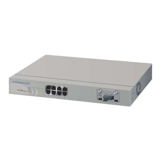
User Manual 1-4. View of 8+1 Managed Ethernet Switch Fig. 1-1 Full View of 8 +1 Managed Ethernet Switch 1-4-1. User Interfaces on the Front Panel (Button, LEDs and Plugs) There are 8 TP Fast Ethernet ports and 1 optional module on the front panel of 8+1 MANAGED ETHERNET SWITCH. - Page 16 User Manual • LED Indicators Color Function System LED POWER Green Lit when AC power is on and good 10/100Mbps Ethernet TP Port 1 to 8 LED Lit when connection with remote device is good LNK/ACT Green Blinks when any traffic is present Off when cable connection is not good Lit when 100Mbps speed is active 100Mbps...
-
Page 17: User Interfaces On The Rear Panel
User Manual 1-4-2. User Interfaces on the Rear Panel There is one fan on the left side for cooling, one 100-240V 50-60 Hz AC Plug and a RS-232 DB-9 interface for configuration or management. AC Line 100-240V 50-60 Hz RS-232 DB-9 Connector Fig. - Page 18 User Manual Fig. 1-5 Front View of 1000Base-SX/LX/LHX/XD/ZX Gigabit Fiber Module • Supports one Gigabit Fiber SC port • Supports full duplex for 1000Mbps • Supports Single/Multi- mode Fiber Cable Fig. 1-6 Front View of 100Base-FX 100Mbps Fiber Module • Supports one 100Base-FX Fiber SC port •...
- Page 19 User Manual Fig. 1-8 Front View of 1000Base-LX Single Fiber WDM Module • Supports one Gigabit Fiber SC port • Supports full duplex for 1000Mbps • Supports Single -mode and Single wire Fiber Cable Publication date: September, 2004 Revision A1...
-
Page 20: Chapter 2. Installation
User Manual 2. Installation 2-1. Starting 8+1 Managed Ethernet Switch Up This section will give users a quick start for: Hardware and Cable Installation - Management Station Installation - Software booting and configuration 2-1-1. Hardware and Cable Installation At the beginning, please do first: ⇒... -
Page 21: Cabling Requirements
User Manual 4. Install the media cable for network connection 5. Repeat the above steps, as needed, for each module to be installed into slot(s) • TP Port and Cable Installation ⇒ In 8+1 MANAGED ETHERNET SWITCH, TP port supports MDI/MDI-X auto- crossover, so both types of cable, straight-through (Cable pin-outs for RJ-45 jack 1, 2, 3, 6 to 1, 2, 3, 6 in 10/100M TP;... -
Page 22: Cabling Requirements For Tp Ports
User Manual 2-1-2-1. Cabling Requirements for TP Ports ⇒ For Fast Ethernet TP network connection The grade of the cable must be Cat. 5 or Cat. 5e with a maximum length of 100 meters. ⇒ Gigabit Ethernet TP network connection ... - Page 23 User Manual The following table lists the types of fiber that we supports and those else not listed here are available upon request. Multi-mode Fiber Cable and Modal Bandwidth Multi-mode 62.5/125µm Multi-mode 50/125µm Modal Modal 1000Base-SX Distance Distance Bandwidth Bandwidth 850nm 160MHz-Km 220m...
-
Page 24: Switch Cascading In Topology
User Manual 2-1-2-3. Switch Cascading in Topology • Takes the Delay Time into Account Theoretically, the switch partitions the collision domain for each port in switch cascading that you may up-link the switches unlimitedly. In practice, the network extension (cascading levels & overall diameter) must follow the constraint of the IEEE 802.3/802.3u/802.3z and other 802.1 series protocol specifications, in which the limitations are the timing requirement from physical signals defined by 802.3 series specification of Media Access Control (MAC) and PHY, and timer from some... - Page 25 User Manual • Typical Network Topology in Deployment A hierarchical network with minimum levels of switch may reduce the timing delay between server and client station. Basically, with this approach, it will minimize the number of switches in any one path; will lower the possibility of network loop and will improve network efficiency.
- Page 26 User Manual Case 2b: Port-based VLAN (See Fig.2-4). Fig. 2-4 Port-based VLAN Diagram 1. VLAN1 members could not access VLAN2, VLAN3 and VLAN4 members. 2. VLAN2 members could not access VLAN1 and VLAN3 members, but they could access VLAN4 members. 3.
- Page 27 User Manual Case3a: The same VLAN members can be at different switches with the same VID (See Fig. 2-6). Fig. 2-6 Tag -based VLAN Diagram Case 3b: Use attribute-based VLAN to centralize all ports for uplinking to Internet (See Fig.2-7). Fig.
-
Page 28: Configuring The Management Agent Of 8+1 Managed Ethernet Switch
User Manual 2-1-3. Configuring the Management Agent of 8+1 Managed Ethernet Switch We offer you three ways to startup the 8+1 MANAGED ETHERNET SWITCH management function. They are RS-232 console, Telnet console, and Web. Users can use any one of them to monitor and configure the switch. You can touch them through the following procedures. -
Page 29: Configuring The Management Agent Of Switch Through The Serial Rs-232 Port
User Manual 2-1-3-1. Configuring the Management Agent of Switch through the Serial RS-232 Port To perform the configuration through RS-232 console port, the switch’s serial port must be directly connected to a DCE device, for example, a PC, through RS-232 cable with DB-9 connector. Next, run a terminal emulator with the default setting of the switch’s serial port. - Page 30 User Manual • Set IP Address, Subnet Mask and Default Gateway IP Address. Please refer to Fig. 2-8 Console Management for details about ex-factory setting. They are default setting of IP address. You can first either configure your PC IP address or change IP address of the switch, next to change the IP address of default gateway and subnet mask.
-
Page 31: Configuring Management Agent Of Switch Through Ethernet Port
User Manual 2-1-3-2. Configuring Management Agent of Switch through Ethernet Port There are three ways to configure and monitor the switch through the switch’s Ethernet port. They are Telnet, Web browser and SNMP manager. The user interface for the last one is NMS dependent and does not cover here. We just introduce the first two types of management interface. -
Page 32: Ip Address Assignment
User Manual Fig. 2-11 the Login Screen for Web 2-1-4. IP Address Assignment For IP address configuration, there are three parameters needed to be filled in. They are IP address, Subnet Mask, Default Gateway and DNS. IP address: The address of the network device in the network is used for internetworking communication. - Page 33 User Manual With the classful addressing, it divides IP address into three classes, class A, class B and class C. The rest of IP addresses are for multicast and broadcast. The bit length of the network prefix is the same as that of the subnet mask and is denoted as IP address/X, for example, 192.168.1.0/24.
- Page 34 User Manual Class D and E: Class D is a class with first 4 MSB (Most significance bit) set to 1-1-1-0 and is used for IP Multicast. See also RFC 1112. Class E is a class with first 4 MSB set to 1-1-1-1 and is used for IP broadcast.
- Page 35 User Manual In this diagram, you can see the subnet mask with 25-bit long, 255.255.255.128, contains 126 members in the sub-netted network. Another is that the length of network prefix equals the number of the bit with 1s in that subnet mask. With this, you can easily count the number of IP addresses matched.
- Page 36 User Manual For different network applications, the subnet mask may look like 255.255.255.240. This means it is a small network accommodating a maximum of 15 nodes in the network. Default gateway: For the routed packet, if the destination is not in the routing table, all the traffic is put into the device with the designated IP address, known as default router.
-
Page 37: Typical Applications
User Manual 2-2. Typical Applications 8+1 Managed Ethernet Switch implements 8 Fast Ethernet TP ports with auto MDIX, supporting Gigabit and Fast Ethernet slot for removable 1 module slot module supported comprehensive fiber types of connection, including SC/ST, MT- RJ, VF-45, LC, BiDi-LC and BiDi-SC as well as Gigabit TP module. For more details on the specification of the switch, please refer to Appendix A. - Page 38 User Manual Fig. 2-15 Peer-to-peer Network Connection Fig. 2-16 Office Network Connection Publication date: September, 2004 Revision A1...
-
Page 39: Chapter 3. Basic Concept And 3-1. Whats The Ethernet
User Manual 3. Basic Concept and Management This chapter will tell you the basic concept of features to manage this switch and how they work. 3-1. What’s the Ethernet Ethernet originated and was implemented at Xerox in Palo Alto, CA in 1973 and was successfully commercialized by Digital Equipment Corporation (DEC), Intel and Xerox (DIX) in 1980. - Page 40 User Manual IEEE 802.2 LLC Data Link Layer IEEE802.3 CSMA/CD MAC IEEE 802.3 PLS Physical Layer ANSI X3T9.5 PMD IEEE 802.3 Fiber Coaxial/STP/UTP This above diagram shows the Ethernet architecture, LLC sub-layer and MAC sub-layer, which are responded to the Data Link layer, and transceivers, which are responded to the Physical layer in OSI model.
- Page 41 User Manual Table 3-1 LLC Format The table 3-1 is the format of LLC PDU. It comprises four fields, DSAP, SSAP, Control and Information. The DSAP address field identifies the one or more service access points, in which the I/G bit indicates it is individual or group address. If all bit of DSAP is 1s, it’s a global address.
-
Page 42: (Mac)
User Manual Fig. 3-2 SAP Format 3-2. Media Access Control (MAC) MAC Addressing Because LAN is composed of many nodes, for the data exchanged among these nodes, each node must have its own unique address to identify who should send the data or should receive the data. In OSI model, each layer provides its own mean to identify the unique address in some form, for example, IP address in network layer. - Page 43 User Manual Bit 47 bit 0 1st byte 2nd byte 3rd byte 4th byte 5th byte 6th byte OUI code Serial number Table 3-3 Ethernet MAC address The first bit of the first byte in the Destination address (DA) determines the address to be a Unicast (0) or Multicast frame (1), known as I/G bit indicating individual (0) or group (1).
- Page 44 User Manual Destination address (DA) — The DA field is used to identify which network device(s) should receive the packet. It is a unique address. Please see the section of MAC addressing. Source addresses (SA) — The SA field indicates the source node. The SA is always an individual address and the left-most bit in the SA field is always 0.
- Page 45 User Manual How does a MAC work? The MAC sub-layer has two primary jobs to do: 1. Receiving and transmitting data. When receiving data, it parses frame to detect error; when transmitting data, it performs frame assembly. 2. Performing Media access control. It prepares the initiation jobs for a frame transmission and makes recovery from transmission failure.
- Page 46 User Manual Ethernet MAC transmits frames in half-duplex and full-duplex ways. In half- duplex operation mode, the MAC can either transmit or receive frame at a moment, but cannot do both jobs at the same time. As the transmission of a MAC frame with the half-duplex operation exists only in the same collision domain, the carrier signal needs to spend time to travel to reach the targeted device.
- Page 47 User Manual Parameter 10Base 100Base 1000Base value/LAN Max. collision 100 meters for UTP 100 meters for UTP domain DTE to 100 meters 412 meters for fiber 316 meters for fiber Max. collision domain with 2500 meters 205 meters 200 meters repeater Slot time 512 bit times...
-
Page 48: Media Access Control
User Manual 3-3. Flow Control Flow control is a mechanism to tell the source device stopping sending frame for a specified period of time designated by target device until the PAUSE time expires. This is accomplished by sending a PAUSE frame from target device to source device. - Page 49 User Manual Frame Reception In essence, the frame reception is the same in both operations of half duplex and full duplex, except that full-duplex operation uses two buffers to transmit and receive the frame independently. The receiving node always “listens” if there is traffic running over the medium when it is not receiving a frame.
- Page 50 User Manual What if a VLAN tagging is applied? VLAN tagging is a 4-byte long data immediately following the MAC source address. When tagged VLAN is applied, the Ethernet frame structure will have a little change shown as follows. Only two fields, VLAN ID and Tag control information are different in comparison with the basic Ethernet frame.
-
Page 51: How Does A Switch Work
User Manual The maximum length of the extension is equal to the quantity (slotTime - minFrameSize). The MAC continues to monitor the medium for collisions while it is transmitting extension bits, and it will treat any collision that occurs after the threshold (slotTime) as a late collision. - Page 52 User Manual Fig.3-5 Collision Domain Extended Distance Limitations: The diameter of a half-duplex LAN segment is determined by its maximum propagation delay time. For example, in 10M LAN, the most distance of a LAN segment using yellow cable is 2500 meters and 185 meters when using coaxial cable.
- Page 53 User Manual Fig. 3-6 How does a switch operate? A Layer 2 switch uses some features of the Data Link layer in OSI model to forward the packet to the destination port(s). Here we introduce some important features of a switch and how they work. MAC address table When a packet is received on a port of switch, the switch first checks if the packet good or bad and extracts the source MAC address (SA) and destination...
-
Page 54: Snmp
User Manual Mac address aging There is a field in MAC address table used to put the entry’s Age time which determines how long a MAC entry can reside in a switch. The age time is refreshed when a packet with that SA. Usually, the age time is programmable. Transmission schedule In most layer 2 switches, the QoS is supported. - Page 55 User Manual The versions of SNMP So far, there are three version of SNMP existed: SNMP version 1 (SNMP v1), SNMP version 2 (SNMP v2) and SNMP version 3 (SNMP v3). There are lots of features in common among these three versions of SNMP. SNMP v1 is the most popular and its standard specification is described in RFC 1157.
- Page 56 User Manual SMI (Structure of Management Information): It defines the common framework and rules to describe the management information using ISO Abstract Syntax Notation 1 (ASN.1). With the common framework, we can identify the data types that can be used in MIB and specify the parameters in MIB to stand for various information.
- Page 57 User Manual Here are other examples: 1.3.6.1.2.1.2 means Interfaces 1.3.6.1.2.1.11 means snmp 1.3.6.1.4.1.5205 means ex-factory’s private MIB Management Information Base (MIB): MIB is a tree architecture with many leaves which describe the information of all the managed objects in hierarchy way and the way how to access them. The MIB file is described by the syntax of ASN.1.
- Page 58 User Manual There are also many forms of MIB Syntax. Here we introduce some basic forms to help you read the MIB. OBJECT IDENTIFIER OBJECT IDENTIFIER ::= { iso 3} This means org is a sub-identifier 3 of iso (1), the OID of org, org: oid =1.3 OBJECT IDENTIFIER ::= { org 6 }...
- Page 59 User Manual OBJECT-TYPE sysDescr OBJECT-TYPE SYNTAX DisplayString MAX-ACCESS read-only STATUS current DESCRIPTION "A textual description of the entity. This value should include the full name and version identification of the system's hardware type, software operating-system, and networking software." ::= { system 1 } This means sysDescr is a sub-identifier of system (1).
- Page 60 User Manual The SNMP v1 message is composed of the message header and PDU. The first two fields Version and Community comprise the message header, and the third field is the PDU for GET and SET. There is a little difference between two types of PDU.
- Page 61 User Manual Error Status: An enumerated INTEGER type that indicates normal operation or one of five error conditions below. Error Value Meaning noError Proper manager/agent operation The size of the repuired Getresponse PDU exceeds a tooBig local limitation The requested object name did not match the names noSuchName available in the relevant MIB View A SetRequest contained an inconsistent type, length,...
- Page 62 User Manual Cold Start Warm Start Link Down Link Up AuthentacationFailure egpNeighborLoss enterpriseSpecific Table 3-7 Generic Trap type Specific TrapType: When Generic TrapType=6, SpeTrapType indicates which private trap is applied in the SNMP trap. TimeStamp: Indicate the system-up time in unit of 10 ms. SNMP v2 PDU: SNMP v2 has the same message header as SNMP v1 has.
- Page 63 User Manual 3-6. Spanning Tree Protocol Bridge and Bridged LAN Bridge is a device applied to connect two or more LAN segments to be a larger network. A LAN using bridges to connect smaller ones is called Bridged LAN. According to IEEE802.1W specification, the maximum bridge diameter can be up to 7, which means you can cascade up to 7 bridges in a network path.
- Page 64 User Manual Now PC C sends a packet to PC A, Bridge A adds the MAC address of PC C and port number to its lookup table and finds both stations are at LAN A, it will not pass the packet to LAN 2. This is called filtering. Learning and flooding keeps continuing as long as the network is working.
- Page 65 User Manual LAN A and LAN B are combined by Bridge A and Bridge B into a Bridge LAN. Although one of the two links is used to act as a redundant link, a loop is introduced. The loop will cause message duplication broadcast storm and let the bridges learn the MAC address with the wrong port number.
- Page 66 User Manual Root Bridge: Logically, the root bridge is the center of the network. It is unique in a bridged LAN. Every bridge in the LAN knows the ID of the root bridge. It monitors the topology of STP. When any STP topology is changed anywhere, the bridge noticing the change event must pass a Topology Change Notification (TCN) to root bridge.
- Page 67 User Manual Bridge Message Age When bridged LAN components are failed or removed, which may result in the change of STP topology, the worse information will be propagated to other bridges. The MAC on each bridge can signal failure condition, but, unfortunately, not all failure conditions can be propagated in this way.
- Page 68 User Manual Root Path Cost: It may have more than one path in a bridge able to reach the root bridge. From the viewpoint of a single path, the summation of the path cost of each bridge on this path is the root path cost of the bridge port. But, from a bridge’s viewpoint, the very one with the smallest cost value among these root path cost is the root path cost of the bridge.
- Page 69 User Manual How dose a Spanning Tree Protocol Work? Basically, STP operation is transparent to all stations unaware that which LAN segment they are connected to. At the beginning, each bridge in a bridged LAN assumes it is the root bridge, a while later, all bridges start gathering all other bridge’s information by exchanging the message through BPDU and come out the real root bridge, designated bridge and remove the loops.
- Page 70 User Manual A port immediately enters Listening state in only one condition: When STP protocol entity determines that this port is a Designated Port or Root Port, it will enter Listening state from Blocking state. The following features are the behavior of a port in the Listening state: 1.
- Page 71 User Manual Disabled: A port in the Disabled state is a port whose MAC operational state is disabled through the operation of management. The state can be entered from any other state mentioned above by the operation of management. A port leaves this state when MAC operational function is enabled manually.
- Page 72 User Manual Bridege 2--- BridgeID=32768 , MAC: 00.40.00.00.00.02 Port1 PortID=128 , 01 PathCost=5 Port2 PortID=128 , 02 PathCost=5 Port3 PortID=128 , 03 PathCost=25 We will find the fact as follows: 1. Bridge 0 is the root bridge of the bridged LAN. Its Root Path Cost is 0 because it itself is the root bridge.
- Page 73 User Manual Another Example---Changing some STP settings of a Bridge. Now we reconfigure the settings of Bridge 0 ~ Bridge 2 as follows: Bridge 0 --- BridgeID=32768 , MAC: 00.40.00.00.00.00 Port1 PortID=128 , 01 PathCost=10 Bridege 1--- BridgeID=32768 , MAC: 00.40.00.00.00.01 Port1 PortID=128 , 01 PathCost=40 Port2 PortID=128 , 02 PathCost=10 Port3 PortID=128 , 03 PathCost=10...
- Page 74 User Manual We will find the tree topology is changed in Fig.3-12 as the parameters of STP have changed. 1. Bridge 0 is still the root bridge of the bridged LAN, Its Root Path Cost is 0 because it itself is the root bridge. 2.
-
Page 75: Spanning Tree Protocol
User Manual 3-7. Virtual LAN What is a VLAN? It is a subset of a LAN. Before we discuss VLAN, we must understand what LAN is. In general, a LAN is composed of different physical network segments bridged by switches or bridges which attach to end stations in the same broadcast domain. - Page 76 User Manual Fig. 3-14 Now we apply VLAN technology to configure the system shown as the figure above. We can partition the users into the different logical networks which have their own broadcast domain. The traffic will not disturb among these logical networks. The users 1x (x denotes a ~ d) are members of VLAN 1.
- Page 77 User Manual There are many types of VLAN applied. Most popular is port-based VLAN, tag-based VLAN and protocol-based VLAN. Port-based VLAN Some physical ports are configured as members of a VLAN. All stations attached on these ports can communicate with each other. Tag-based VLAN It identifies the membership by VLAN ID, no matter where the packet comes from.
- Page 78 User Manual VLAN-tagged frame: An Ethernet frame, carrying VLAN tag field, contains VLAN identification without the value of 0 and 4095, and priority information. Priority-tagged frame: An Ethernet frame, carrying VLAN tag field, contains VLAN identification with the value of 0 and priority information. Untagged frame: An Ethernet frame carries no VLAN tag information.
- Page 79 User Manual Ingress Rule: Each packet received by a VLAN-aware bridge will be classified to a VLAN. The classification rule is described as follows. 1. If the VID of the packet is null VID (VID=0)or this packet is an untagged packet: a.
- Page 80 User Manual How does a Tagged VLAN work? If the ingress filtering is enabled and when a packet is received, VLAN bridge will first check if the VID of the packet presents. 1). If the packet has a non-zero VID, VLAN bridge will apply this VID as the VLAN ID of the packet in the network.
-
Page 81: Garp Vlan Registration
User Manual 3-8. GARP VLAN Registration Protocol (GVRP) GVRP is an application based on Generic Attribute Registration Protocol (GARP), mainly used to automatically maintain the group membership information of the VLANs, and thus save time and troubles. If switches in the network do not support GVRP, administrator has to reconfigure these switches when change is needed. - Page 82 User Manual Generic Attribute Registration Protocol (GARP) This section will give you an overview of Generic Attribute Registration Protocol (GARP). GARP provides a generic framework to serve the devices, switches or end station, to register and de-register attribute values through GARP Information Propagation (GIP), with each other, as well as defines operation rule and variables.
- Page 83 User Manual JoinTimer Attribute N Attribute … LeaveTimer Attribute 1 Applicant Registrar Applicant LeaveAllTimer Registrar Applicant Registrar Fig.3-18 GID Architecture GVRP BPDU Format 2 bytes 1 byte 4 bytes Protocol 01-80-c2-00- DSAP SSAP Message SA length …… Message Marker 00-21 0x42 0x42 0x03...
- Page 84 User Manual The first byte of Attribute Type is 0x01, attribute message describes VLAN. DA 01-80-c2-00-00-21 is reserved for GVRP. DSAP:SSAP=0x4242 pair means Spanning tree protocol. Protocol ID 0x0001 is reserved for GARP. Attribute Length: it is defined by the type of Attribute Event. If Attribute Event is LeaveAll, Attribute Length equals 2.
- Page 85 User Manual 0: LeaveAll When GID issues this type of message, it means that GID is collecting garbage. This implies the port issuing the message is going to leave all VLAN groups. If its LP wishes it not to leave a specified VLAN group, the LP has to issue the message of either JoinIn or JoinEmpty with the VID of the specified VLAN to the port.
-
Page 86: Link Aggregation
User Manual 3-9. Link Aggregation Basically, Link Aggregation is to aggregate the bandwidth of more than one port to an assigned logical link. This highly increases total bandwidth to the targeted device. There is more than one Link Aggregation technology in many vendors’ switch products already, which may cause the problem of interoperability. - Page 87 User Manual Terminology Link Aggregation: It is a method to have multiple physical links with the same media and speed bundled to be a logical link forming a Link Aggregation Group with a group ID. With the viewpoint of MAC client, each Link Aggregation Group is an independent link. There are three cases of link used in the network, which are switch to switch, switch to station and station to station.
- Page 88 User Manual What is LACP? By IEEE 802.3ad’s definition shown in Fig. 3-21, Link Aggregation is sub- layer between MAC client and MAC entity. It obviously shows that it connects to multiple MACs. This means it provides a single interface to MAC client. When multiple MACs are applied to LACP sub-layer, these ports are aggregated.
- Page 89 User Manual Frame Distribution: This function is responsible for forwarding the frame received from MAC client to the destination port. Frame Collection: This function is responsible for collecting the frames received from different MACs and transferring to MAC client. Aggregator: It performs the function of Frame Distribution, Frame Collection, and Aggregator Parser/Multiplexers.
- Page 90 User Manual System ID: Each network device has its own unique system id composed of MAC address and priority. Aggregation can be created only among links when connected to the same system. If a physical link of a LACP group is connected to one device, and a physical link is connected to another device, this will have the trunk stopped and LACP will have these ports to be individual normal single port.
- Page 91 User Manual After exchanging LACP PDU between switch A and switch B, switch A will contain the capability information of switch B, and vice versa. The ports 1&2&3 of switch A have their own Link Aggregation Group ID (LAG ID) comprising Actor’s system ID, Actor’s port ID, Partner’s system ID and Partner’s port ID.
- Page 92 User Manual Reserved TLV_type=Collector 0x03 means an Collector type information Information 0x03 Collector_Information_Length This field indicates the length of this TLV-tuple. Partner information uses 0x10 bytes long. = 16 CollectorMaxDelay The value of CollectorMaxDelay of the station transmitting the LACPDU Reserved TLV_type = Terminator 0x00 0x00 means an terminator type information...
- Page 93 User Manual 8. Expired 1: Actor’s Receive machine is in the EXPIRED state, 0: Actor’s Receive machine is not in the EXPIRED state. The received values of Defaulted and Expired state are not used by LACP. Publication date: September, 2004 Revision A1...
-
Page 94: Igmp Snooping
User Manual 3-10. IGMP Snooping The function IGMP snooping is used to establish the multicast groups to forward the multicast packet to the member ports, and, in nature, avoid wasting the bandwidth while IP multicast packets are running over the network. The reason is that a switch that does not support IGMP or IGMP snooping unable to distinguish multicast packet from broadcast packet, so it can only treat them all as broadcast packets. - Page 95 User Manual Terminology Internet Group Multicast Protocol (IGMP): IGMP is a protocol at layer 3, dedicatedly serving the setup and maintenance of the membership as well as the forwarding of the multicast traffic. A network device can register its membership to a router or switch to be the member of the multicast group(s).
- Page 96 User Manual Leave Group Message: This is a message to have a port leaved a specified multicast group and no association exists between the port and the multicast group. In IGMP version 1, there is no “Leave” mechanism. In that situation, the member who wants to leave the group, the only way is to keep silence and ignore the query.
- Page 97 User Manual In Layer 2 frames: • Source MAC address: MAC address of the host • Destination MAC address: MAC address for the 32-bit group address (class D IP address). It looks like 01:00:5E:XX:XX:XX Layer 3 packet: • Source IP address: IP address of the host •...
- Page 98 User Manual In IGMP version 2, if a host would not like to receive the multicast traffic any more, it can issue an IGMP Leave Message. The switch supporting IGMP v2 will remove the association of the specified ports and the specified group. IGMP PDU IGMP version 1 (RFC 1112) messages are transmitted with the following format.
-
Page 99: Dynamic Host Configuration
User Manual MRT: Maximum Response Time This field makes response only to the membership query messages. The sender must assign a value in unit of one-tenth second to this field for the receiver’s longest response time. When a host receives a membership query message, it must reply a membership report message within MRT. - Page 100 User Manual It is obviously that Dynamic allocation is much more flexible than Automatic allocation, especially when there are not enough IP addresses to be used in a network. Besides dynamically allocating IP addresses, DHCP can reserve some addresses for specified devices. It can also assign IP addresses by the ranking of MAC address.
- Page 101 User Manual Actually, not all DHCP clients will unconditionally accept the offer of DHCP server, especially in those hosts installed their own TCP/IP related customized software. DHCP can also use Dhcprequest to ask the choice, and these choices will be filled with different codes in the DHCP Option field listed in the table below. Code Description Sub-net Mask...
- Page 102 User Manual Fig. 3-25 As to the due of the lease of an IP address, its typical time interval is 1 ~ 30 days. DHCP client will also issue Dhcprequest to ask for lasting the lease time when the slapped time reaches a half of the whole lease time interval (1/2 lease time). DHCP client uses Dhcpack via unicast to update the lease time of an IP address.
- Page 103 User Manual For sure, you can deploy a DHCP server for each LAN. This may induce management issue. Basically, it depends on your network environment. DHCP format: OP(1) HTYPE(1) HLEN(1) HOPS(1) TRANSACTION ID (xid) (4 bytes) SECONDS(2 bytes) FLAGS(2 bytes) Ciaddr (4 bytes) yiaddr(4 bytes) siaddr(4 bytes)
- Page 104 User Manual yiaddr This field is the allocated IP address encapsulated in Dhcpoffer and Dhcpack packet by server. Siaddr The packet sent from server will be encapsulated with this information in Dhcpoffer, Dhcpack or Dhcpnack if client is booted from network. The information of this field is the server address for the specified boot code.
-
Page 105: Chapter 4. Operation Of
User Manual 4. Operation of Web-based Management This chapter instructs you how to configure and manage the switch through the web user interface it supports, to access and manage the 8 10/100Mbps + 1 module. The switch provides 8 fixed fast Ethernet ports + 1 module slot supporting Gigabit and Fast Ethernet modules. -
Page 106: Web Management Home Overview
User Manual Fig. 4-1 4-1. Web Management Home Overview After you login, the switch shows you the system information as Fig. 4-2. This page is default and tells you the basic information of system, including “Model Name”, “System Description”, “Location”, “Contact”, “System Up Time”, “Current Time”, “Mac Address”, “BIOS Version”, “Firmware Version”, “Hardware-Mechanical Version”, “RAM Size”, “Flash Size”, “System Temperature”, “Series Number”, “Device Port”, “Power Voltage”, “Case Detection”... - Page 107 User Manual The Information of Page Layout • On the top side, it shows the front panel of the switch. In the front panel, the linked ports will display green; as to the ports, which are link off, they will be dark.
- Page 108 User Manual Fig. 4-3 Port Status Information In Fig. 4-3, it shows the basic information of the clicked port. With this, you’ll see the information about the port status, traffic status and bandwidth rating for egress and ingress respectively. The following is the description of the nomenclature in Fig. 4-2. Function name: System Information Function description:...
- Page 109 User Manual Current Time: Show the system time of the switch. Its format: day of week, month, day, hours : minutes : seconds, year. For instance, Wed, Apr. 23, 12:10:10, 2004. MAC Address: It is the Ethernet MAC address of the management agent in this switch. BIOS Version: The version of the BIOS in this switch.
-
Page 110: Port Status And Counters
User Manual 4-2. Port Status and Counters Six functions, including Port Current Status, Port Counters, Port Configuration, Port Mirror, Port Quality Statistic, and Port Quality Rule Setting are contained in this function folder for port monitor and management. Each of them will be described in detail orderly in the following sections. - Page 111 User Manual Function name: Port Current Status Function Description: Report the latest updated status of all ports in this switch. When any one of the ports in the switch changes its parameter displayed in the page, it will be automatically refreshed the port current status about every 5 seconds. Parameter Description: Port: Display the port number.
- Page 112 User Manual Speed / Duplex Mode: Display the speed and duplex of all port. There are three speeds 10Mbps, 100Mbps and 1000Mbps supported in the switch. The duplex supported is half duplex and full duplex. The status of speed/duplex mode is determined by 1) the negotiation of both local port and link partner in “Enabled”...
- Page 113 User Manual Media Type: Port 9 is an optional module, which support either fiber or UTP media with either Gigabit Ethernet (1000Mbps) or 10/100Mbps Fast Ethernet port. They may have different media types and speed. Especially, fiber port has comprehensive types of connector, distance, fiber mode and so on.
-
Page 114: Port Counters
User Manual 4-2-2. Port Counters The function Port Counter collects any information and provides the counting about the traffic of the port, no matter the packet is good or bad. In Fig. 4-5, the window can show only one port counter information at the same time. - Page 115 User Manual Rx Byte: Total received bytes. Tx Bad Packet: The counting number of the packet transmitted abnormally. Rx Bad packet: The counting number of the packet received which is treated as bad. Collision Counter: Collision times. Tx Abort Packet: The counting number of the packet aborted during transmission.
- Page 116 User Manual 256-511 byte Packets Received: Show the counting number of the packet with the length between 256 to 511 bytes. 512-1023 byte Packets Received: Show the counting number of the packet with the length between 512 to 1023 bytes. 1.0-1.5Kbyte Packets Received: Show the counting number of the packet with the length between 1024 to 1536 bytes.
-
Page 117: Port Configuration
User Manual 4-2-3. Port Configuration Port Configuration is applied to change the setting of each port. In this configuration function, you can set/reset the following functions, Port State, Auto Negotiation, Speed/Duplex, and Flow Control. All of them are described in detail below. - Page 118 User Manual When disabled, if you want to set up a connection successfully, you must have both port configuration of local port and linked partner be the same. If their configuration is different, the link will not be set up successfully. In the switch, the 100Mbps fiber module supports forced mode only;...
-
Page 119: Port Mirror
User Manual 4-2-4. Port Mirror The switch supports Port Mirror function that the user is able to easily inspect and monitor the traffic of designated port(s). To use this port mirror function, first, enable the Port Mirror function, here you can choose the port mirror status you want. Disable and Enable are contained in this status list. -
Page 120: Port Quality Statistic
User Manual 4-2-5. Port Quality Statistic This function will display each port quality statistic based on the rules you select. With this feature, you can easily monitor the status of physical link and traffic quality which are degraded by too many error packets, lost link and etc., on the switch. -
Page 121: Port Quality Rule Setting
User Manual R2 Now: Accumulated counting regulated by Rule 2: When the total times of link off on the port exceed X times in a period of 10 sec(s), where X is defined by user, the counter R2 Now is increased 1. The counter will be cleared while user use clear button. - Page 122 User Manual Parameter description: Rule 1: Enable button determines if able to configure this rule. The sentence “When link off exceed X sec(s)” means if the lasted link-off time of a port is more than X seconds, the function Port Quality Statistic will be activated and increment one in Rule 1 counters, including Rule 1 Now and Rule 1 All.
-
Page 123: Configuration
User Manual 4-3. Configuration Four functions, including System Configuration, Network Management, Trap/Alarm Configuration, and Save Configuration are contained in this function folder for system and network management. Each of them will be described in detail orderly in the following sections. Configuration System Configuration Network Management... -
Page 124: Username / Password Setting
User Manual 4-3-1-1. Username / Password Setting In this function, only administrator can create, modify or delete the username and password. Administrator can modify other guest identities’ password without confirming the password but it is necessary to modify the administrator-equivalent identity. -
Page 125: Ip Configuration
User Manual 4-3-1-2. IP Configuration IP configuration is one of the most important configurations in the switch. Without the proper setting, network manager will not be able to manage or view the device. The switch supports both manual IP address setting and automatic IP address setting via DHCP server. - Page 126 User Manual IP address: Users can configure the IP settings and fill in new values if users set the DHCP function “Disable”. Then, click <Apply> button to update. When DHCP is disabled, Default: 192.168.1.1 If DHCP is enabled, this field is filled by DHCP server and will not allow user manually set it any more.
-
Page 127: System Time Setting
User Manual DNS: It is Domain Name Server used to serve the translation between IP address and name address. The switch supports DNS client function to re-route the mnemonic name address to DNS server to get its associated IP address for accessing Internet. - Page 128 User Manual NTP: NTP is Network Time Protocol and is used to sync the network time based Greenwich Mean Time (GMT). If use the NTP mode and select a built-in NTP time server or manually specify an user-defined NTP server as well as Time Zone, the switch will sync the time in a short after pressing <Apply>.
- Page 129 User Manual Day Light Saving End : This is used to set when to stop performing the daylight saving time. Mth: Range is 1 ~ 12. Default: 1 Day: Range is 1 ~ 31. Default: 1 Hour: Range is 0 ~ 23. Default: 0 Fig.
-
Page 130: Location/Contact Setting
User Manual 4-3-1-4. Location/Contact Setting Location is used for specifying where the device is and Contact is used for specifying with whom to contact if there are troubles happened. These two parameters provide manager a convenient way to fast identify the location of the device and maintenance information without checking the notebook. - Page 131 User Manual Fig. 4-13 Network Management There are thirteen functions contained in the network management function folder. Network Management SNMP Configuration Max. Packet Length Setting Broadcasting Suppression IGMP Snooping Misc. Feature Configuration Spanning Tree Configuration Port Trunking Configuration Filtering Configuration VLAN Configuration GVRP Configuration 802.1x Configuration...
-
Page 132: Snmp Configuration
User Manual 4-3-2. SNMP Configuration Any Network Management System (NMS) running the Simple Network Management Protocol (SNMP) can manage the Managed devices equipped with SNMP agent, provided that the Management Information Base (MIB) is installed correctly on the managed devices. The SNMP is a protocol that is used to govern the transfer of information between SNMP manager and agent and traverses the Object Identity (OID) of the management Information Base (MIB), described in the form of SMI syntax. - Page 133 User Manual Default community name for GET: public Default community name for SET: private Default community name for Trap: public Default trap host IP address: 0.0.0.0 Trap: In the switch, there are four trap hosts supported. Each of them has its own community name and IP address;...
-
Page 134: Max. Packet Length Setting
User Manual 4-3-3. Max. Packet Length Setting The switch provides two kinds of Ethernet frame size for the user to set up. One is 1536 bytes and the other is 1522 bytes. After selecting one of these two options and then pressing <Apply> button, the setting will take effect immediately. Default setting is 1522 bytes long, which can afford accommodating the size of the tagged VLAN frame. -
Page 135: Broadcasting Suppression
User Manual 4-3-4. Broadcasting Suppression The Broadcasting Suppression function is used to spread the request broadcast packet into a bigger time frame to prevent the traffic congestion due to broadcast packets from many network devices which may seek its NMS, boot server, DHCP server and many connections predefined when the whole building or block lose the power and then reboot and recover. -
Page 136: Igmp Snooping
User Manual 4-3-5. IGMP Snooping The function, IGMP Snooping, is used to establish the multicast groups to forward the multicast packet to the member ports, and, in nature, avoids wasting the bandwidth while IP multicast packets are running over the network. This is because a switch that does not support IGMP or IGMP Snooping can not tell the multicast packet from the broadcast packet, so it can only treat them all as the broadcast packet. - Page 137 User Manual Parameter description: IGMP snooping mode selection: The switch supports three kinds of IGMP Snooping status, including “Passive”, “Active” and “Disable”. Passive: In Passive Snooping mode, the IGMP snooping will not periodically poll the hosts in the groups. The switch will send a Membership Query message to all hosts only when it has received a Membership Query message from a router.
-
Page 138: Misc. Feature Configuration
User Manual 4-3-6. Misc. Feature Configuration Miscellaneous Feature Configuration gathers many functions, including MAC Address Aging Time Setting, Broadcast Storm Filter Limit, Priority Queue Service, Max. bridge transmit delay bound control and QoS Policy in a page, which cannot be categorized to some function type. They are described below. Function Name: MAC Address Aging Time Setting Function Description:... - Page 139 User Manual Weighted Round Robin (WRR): This is actually a transmission ratio of high priority packet and low priority packet. If you would like to repeatedly send 5 high priority packets first and then 2 low priority packets. You can set a 5 to high weight field and a 2 to low weight field in WRR function row.
- Page 140 User Manual Function name: QoS Policy Function Description: It is used to assign which priority level is high or low. Normally, we map the priority levels 7 – 4 to be high priority and the priority levels 3 – 0 to be low priority.
-
Page 141: Spanning Tree Configuration
User Manual 4-3-7. Spanning Tree Configuration The Spanning Tree Protocol (STP) is a standardized method (IEEE 802.1D) for avoiding loops in switched networks. When STP is enabled, ensure that only one path is active between any two nodes on the network at a time. User can enable Spanning Tree Protocol on switch’s web management and then set up other advanced items. - Page 142 User Manual All bridges in the LAN will re-learn and determine which the root bridge is. Maximum Age time is assigned by root bridge in unit of seconds. Default is 20 seconds. Current Forward Delay (sec): Show the current root bridge forward delay time. The value of Forward Delay time is set by root.
-
Page 143: Stp Configuration
User Manual 4-3-7-2. STP Configuration The STP, Spanning Tree Protocol, actually includes RSTP. In the Spanning Tree Configuration, there are six parameters open for the user to configure as user’s idea. Each parameter description is listed below. Function name: STP State Setting Function description: User can set the following Spanning Tree parameters to control STP function enable/disable, select mode RSTP/STP and affect STP state machine... - Page 144 User Manual Forward Delay: You can set the root bridge forward delay time. This figure is set by root bridge only. The forward delay time is defined as the time spent from Listening state moved to Learning state and also from Learning state moved to Forwarding state of a port in bridge.
- Page 145 User Manual Function name: Port Setting Function description: In the STP Port Setting, one item selection and five parameters settings are offered for user’s setup. User can disable and enable each port by selecting each Port Status item. User also can set “Path Cost” and “Priority” of each port by filling in the desired value and set “Admin Edge Port”...
- Page 146 User Manual Priority: Priority here means Port Priority. Port Priority and Port Number are mixed to form the Port ID. Port IDs are often compared in order to determine which port of a bridge would become the Root Port. The range is 0 –...
-
Page 147: Port Trunking Configuration
User Manual Fig. 4-21 Spanning Tree Port Setting 4-3-8. Port Trunking Configuration The Port Trunking Configuration is used to configure the settings of Link Aggregation. You can bundle more than one port with the same speed, full duplex and the same MAC to be a single logical port, thus the logical port aggregates the bandwidth of these ports. - Page 148 User Manual Function name: Port Trunking Setting Function description: Port trunking setting is used to choose the trunk mode, static trunk and dynamic trunk, and configure trunk groups. When you move some ports to LACP group, these ports will be disappeared in the Available Ports list. If you do not let a port joined to a LACP group, just click it on LACP window and press <Del>>>...
- Page 149 User Manual Available Ports: In the switch, there are 8 available ports for selection. You can choose at most 4 ports for each trunking group. After deciding, you just have to move them into LACP window by pressing <<<Add> button. If this is the case you want, then press <Apply>...
- Page 150 User Manual Function name: Trunking Port Information Function description: To display the current trunk group information of the switch. It will show you the GID (trunking group ID), port members, LACP state and active ports. Parameter description: GID: Trunking Group ID. Valid value is 1~7. Port Members: Show member ports of each trunking group.
- Page 151 User Manual Function name: Dynamic Active Trunking Port Information Function description: Show the information of the dynamic trunking group, in which active ports, system priority, port priority, MAC address, key and so on for actor and partner will be included. For more details, please see the description below. In this function, you can even see which ports on Actor connect to which ports on Link Partner.
- Page 152 User Manual Function name: Static Active Trunking Port Information Function description: Show the GID and port members of the static trunking group. Parameter description: GID: An ID of an active static trunk. Port Member: Show the port members of a trunk link. Static Active Trunking Port Information Fig.
- Page 153 User Manual Function name: LACP State Activity Function description: In the LACP State Activity, user can tick each port to let it stay in LACP active status or in passive status. These settings will be taken effect immediately by pressing the <Apply> button. Note: When you would like to setup a trunk link between two switches, one of them at least must be in active status.
-
Page 154: Filtering Configuration
User Manual 4-3-9. Filtering Configuration The filtering function in the switch is used to filter unauthorized MAC address from accessing the switch based on some simple rules. The switch provides four types of filtering function for security configuration. They are Allowed Forwarding MAC Address, Port Security Setting, Denied Forwarding MAC Address and Global Allowed MAC Address, in which the functions Allowed Forwarding MAC Address, Denied Forwarding MAC Address and Global Allowed MAC Address can be... - Page 155 User Manual For adding a MAC address entry in the allowed table, you just need to fill in four parameters: MAC address, associated port, priority and VID. Just select the MAC address entry you want and click <Delete> button, you also can remove it.
- Page 156 User Manual Function name: Allowed Forwarding Maximum Entry Function description: This function is to set per port. Only the MAC addresses set in this port can be granted to access the network through the switch. The PCs with these allowed MAC entries accessing the switch from other ports are not allowed. The maximum entry per port supported is 512.
- Page 157 User Manual Fig. 4-30 Port Security Setting Function name: Denied Forwarding MAC Address Function description: Denied Forwarding MAC Address is a function that denies the packet forwarding if the packet’s MAC Address is listed in the filtering MAC Address table. User can very easily maintain the table by filling in MAC Address and VID(VLAN ID) field individually.
- Page 158 User Manual Fig. 4-31 Function name: Denied Forwarding Maximum Entry Function description: This function is used to deny the pre-configured unauthorized user by checking if the source node’s MAC is matched with the denied table. The PCs with the MAC addresses listed in the denied table is rejected to access the network from any port of the switch.
- Page 159 User Manual Fig. 4-32 Function name: Global Allowed MAC Address Function description: Global Allowed MAC address is used for managing the devices in convenience. The network nodes with pre-configured Global Allowed MAC Address can access the network behind the switch from any port on the switch. This is very convenient in the secured network.
- Page 160 User Manual Fig. 4-33 Function name: Global Allowed Maximum Entry Function description: This function is used to set the maximum number of Global Allowed Entry. The supported range is 0 – 50. Parameter description: Maximum Entry: The maximum number of Global Allowed Entry. The valid range is 0 – 50. Default: 0 Fig.
-
Page 161: Vlan Configuration
User Manual 4-3-10. VLAN Configuration VLAN configuration is used to partition your LAN into small ones as your demand. Properly configuring it, you can gain not only improving security and increasing performance but greatly reducing VLAN management. The switch supports Port-based VLAN and Tag-based VLAN (802.1q) as well as protocol VLAN (802.1v). - Page 162 User Manual Fig. 4-35 VLAN State Setting Function name: VLAN Group Setting Function description: It shows the existed information of VLAN Groups List and maintains them, i.e. modify and delete one of them. User also can add a new VLAN group by inputting a new VLAN name and VLAN ID.
- Page 163 User Manual Fig. 4-36 VLAN Group Setting Function name: Tag Base VLAN Group Setting Function description: If you are in tag-based VLAN, it will show the name of the existed VLAN and VID. The switch stores the configuration of port-based VLAN and tag-based VLAN separately.
- Page 164 User Manual Parameter description: VLAN Name: The name defined by administrator is associated with a VLAN group. Valid letter is A-Z, a-z and 0-9. Other special characters will not be accepted. The maximal length is 12 characters. VLAN ID: VLAN identifier. Each tagged VLAN must be assigned a VID. Valid VID: 1 –...
- Page 165 User Manual Tag/Untag: This is an egress rule of the port. Here you can choose untag or tag. Tag means the outgoing packets must carry VLAN tag header. Untag means the outgoing packets carry no VLAN tag header. Fig. 4-37 VLAN Configuration Publication date: September, 2004 Revision A1...
- Page 166 User Manual Function name: Port Base VLAN Group Setting Function description: Select VLAN member for new or existed port-based VLAN groups. In VLAN Group Setting, user can create a new VLAN group by inputting a new VLAN name. User also can edit VLAN name, priority and VLAN members of any created VLAN group.
- Page 167 User Manual Function name: VLAN Port VID Setting (for Tag Only) Function description: In this function, there are two options implemented, Rule 1 and 2 for VLAN ingress rule. Rule 1 is to decide if the device allows forwarding the frame on a non-member port of the specific VLAN.
- Page 168 User Manual Fig. 4-39 VLAN Port VID Setting Function name: Protocol VLAN Setting Function description: Protocol-based VLAN is based on 802.1q tag VLAN and is a kind of classification rule based on tag information. You must apply tagged VLAN first and then apply protocol-based VLAN.
- Page 169 User Manual Parameter description: Frame Format: The protocol based VLAN supported frame formats as below: Ethernet II or LLC Others RFC 1042 SNAP 802.1H SNAP Others Protocol: EtherType Protocol 0x0800 0x0806 0x809B AppleTalk 0x803F AppleTalk AARP 0x8137 Novell IPX 0x80C4 Banyan VINES 0x80C5 Banyan VINES...
-
Page 170: Gvrp Configuration
User Manual 4-3-11. GVRP Configuration GVRP is an application based on Generic Attribute Registration Protocol (GARP), mainly used to automatically and dynamically maintain the group membership information of the VLANs The GVRP offers the function providing the VLAN registration service through a GARP application. It makes use of GARP Information Declaration (GID) to maintain the ports associated with their attribute database and GARP Information Propagation (GIP) to communicate among switches and end stations. - Page 171 User Manual Parameter description: Join Time: Used to declare the Join Time in unit of centisecond. Valid time range: 20 –100 centisecond, Default: 20 centisecond. Leave Time: Used to declare the Leave Time in unit of centisecond. Valid time range: 60 –300 centisecond, Default: 60 centisecond.
- Page 172 User Manual Forbidden: It is Registration Forbidden. The Registrar ignores all GARP messages, and all members remain in the unregistered (EMPTY) state. Restricted Mode: This function is used to restrict dynamic VLAN be created when this port received GVRP PDU. There are two modes, disable and enable, provided for the user’s choice.
- Page 173 User Manual Function name: Static Group Information Function description: To show the static group member and their information. Parameter description: Current Static Group Number: This is the counter to be incremented accordingly, when the maximum of VLAN is reached and a new one is tried to join into this device. Of course, this new will be rejected.
- Page 174 User Manual Function name: Dynamic Group Information Function description: To show the dynamic group member and their information. Parameter description: Current Dynamic Group Number: This is the counter to be incremented accordingly when the maximum of VLAN is reached and a new one is tried to join into this device. Of course, this new will be rejected.
- Page 175 User Manual Function name: GVRP Counter Function description: All GVRP counters are mainly divided into Receive and Transmit two categories to let you monitor the GVRP actions. Actually, they are GARP packets. Fig. 4-45 GVRP Counter Parameter description: Received: Total GVRP Packets: Total GVRP BPDU is received by the GVRP application.
- Page 176 User Manual LeaveEmpty Message Packets: Number of GARP BPDU with Leave Empty message is received by the GARP application. Empty Message Packets: Number of GARP BPDU with Empty message is received by the GARP application. Transmitted: Total GVRP Packets: Total GARP BPDU is transmitted by the GVRP application. Invalid GVRP Packets: Number of invalid GARP BPDU is transmitted by the GVRP application.
-
Page 177: Configuration
User Manual 4-3-12. 802.1x Configuration 802.1x port-based network access control provides a method to restrict users to access network resources via authenticating user’s information. This restricts users from gaining access to the network resources through a 802.1x-enabled port without authentication. If an user wishes to touch the network through a port under 802.1x control, he (she) must firstly input his (her) account name for authentication and waits for gaining authorization before sending or receiving any packets from a 802.1x-enabled port. - Page 178 User Manual The overview of operation flow for the Fig. 4-46 is quite simple. When Supplicant PAE issues a request to Authenticator PAE, Authenticator and Supplicant exchanges authentication message. Then, Authenticator passes the request to RADIUS server to verify. Finally, RADIUS server replies if the request is granted or denied.
- Page 179 User Manual Authentication server Fig. 4-47 Authenticator Supplicant A The Fig. 4-48 shows the procedure of 802.1x authentication. There are steps for the login based on 802.1x port access control management. The protocol used in the right side is EAPOL and the left side is EAP. At the initial stage, the supplicant A is unauthenticated and a port on switch acting as an authenticator is in unauthorized state.
- Page 180 User Manual If user ID and password is correct, the authentication server will send a Radius-Access-Accept to the authenticator. If not correct, the authentication server will send a Radius-Access-Reject. When the authenticator PAE receives a Radius-Access-Accept, it will send an EAP-Success to the supplicant. At this time, the supplicant is authorized and the port connected to the supplicant and under 802.1x control is in the authorized state.
- Page 181 User Manual There are three types of authentication supported in the switch. They are SingleHost 802.1X, MultiHost 802.1X and Advanced 802.1X. In SingleHost mode, for the devices connected to this port, only the supplicant which successes to pass the authentication can access the network. The remained devices won’t be allowed to access the network.
- Page 182 User Manual Function name: 802.1x State Setting Function description: This function is used to configure the global parameters for RADIUS authentication in 802.1x port security application. Parameter description: Authenticator: Master switch to turn 802.1x port security function ON or OFF. Server: RADIUS server IP address for authentication.
- Page 183 User Manual Function name: 802.1x Port Setting Function description: This function is used to configure the parameters for each port in 802.1x port security application. Parameter description: Port Number: It is the port number to be selected for configuring its associated 802.1x parameters which are Port control, reAuthMax, txPeriod, Quiet Period, reAuthEnabled, reAuthPeriod, max.
- Page 184 User Manual Quiet Period(0-65535 s): A period of time during which we will not attempt to access the supplicant. Deafult: 60 seconds reAuthEnabled: Choose whether regular authentication will take place in this port. Default: ON reAuthPeriod(1-65535 s): A non-zero number seconds between the periodic re-authentication of the supplicant.
- Page 185 User Manual Function name: 802.1x Port Setting Function description: This function is used to configure the parameters for each port in 802.1x port security application. Parameter description: Port Number: It is the port number to be selected for configuring its associated 802.1x parameters which are Port control, reAuthMax, txPeriod, Quiet Period, reAuthEnabled, reAuthPeriod, max.
- Page 186 User Manual Quiet Period(0-65535 s): A period of time during which we will not attempt to access the supplicant. Deafult: 60 seconds reAuthEnabled: Choose whether regular authentication will take place in this port. Default: ON reAuthPeriod(1-65535 s): A non-zero number seconds between the periodic re-authentication of the supplicant.
- Page 187 User Manual Fig. 4-50 Function name: 802.1x Port Mode Function description: Set the operation mode of 802.1X for each port. In this device, it supports three types of operation mode, Singlehost, Multihost and Advanced mode. Parameter description: Port No.: Indicate which port is selected to configure the 802.1x operation mode. 802.1x Mode: 802.1x operation mode.
- Page 188 User Manual 802.1x with Singlehost In Singlehost mode, for the devices connected to this port, only the supplicant which successes to pass the authentication can access the network. The remained devices will not be allowed to access the network. If the supplicant’s first time authentication fails, the switch will accept another supplicant’s authentication request.
- Page 189 User Manual Function name: 802.1x Port Status and Setting Function description: Shows each port status. In the four mode options supported in the function 802.1x port mode, it shows different status information. In Multihost mode, it shows the port number and its status, authorized or unauthorized. In Singlehost mode, it shows the port number, MAC address and status.
- Page 190 User Manual 802.1x with Multihost mode: When selecting 802.1x with Multihost mode for a port in the function 802.1X Port Mode Configuration, Devices can access the network through this port once the authenticator is authorized. The Port Status will show the following screen. If the port is granted to access the network, the port status is authorized, otherwise, unauthorized.
- Page 191 User Manual Fig. 4-54 Advanced 802.1x mode: When selecting Advanced 802.1x mode for a port in the function 802.1X Port Mode Configuration, the criteria to pass the port is more strict. Only the device issuing the EAPOL-Request with the pre-configured MAC address and even VID, and being granted to access can access the network through this port once the authenticator is authorized.
- Page 192 User Manual After a device is successfully authenticated on a port supporting advanced 802.1x, the switch will add this MAC address to the VLAN group it belongs to, and that device can access the network through this port. When Tag is OFF, it means VID is exactly the PVID, not offered by authentication server.
- Page 193 User Manual Tag: It determined the source of VID. There are two options, OFF and ON. ON means the authentication server will offer VID. Only the packet with the same VID as that the one provided by authentication server can access the network if the device is authorized, otherwise, can’t access the network even it has the pre-configured MAC address.
- Page 194 User Manual Delete: This function is used to delete the advanced 802.1x MAC entries. Entry Status: This function is performed by clicking the button <Entry Status> and shows the MAC address and port status in association with the selected port. The port status is either Authorized or Unauthorized. Fig.
-
Page 195: Failover Configuration
User Manual 4-3-13. Failover Configuration The failover function provides a backup link for an existed link. This function is different from Link Aggregation (Trunking) and LACP. The switch provides up to 2 failover pairs. When you configure a pair of failover, the switch will internally decide which link is active, the other will be blocked at the same time. - Page 196 User Manual Function name: Failover Rule Setting Function description: In the failover rule setting function, the switch provides three rules as the criteria to change the traffic from active port to alternate port. Any failover switch action will trigger SNMP trap event. The SNMP trap event will notify SNMP manager by sending trap massage.
-
Page 197: Trap/Alarm Configuration
User Manual 4-3-14. Trap/Alarm Configuration Trap/Alarm Configuration Trap Events Configuration Alarm Configuration Function name: Trap Events Configuration Function description: The Trap Events Configuration function is used to enable the Advanced Managed Ethernet Switch to send out the trap information while pre-defined trap events occurred. - Page 198 User Manual FAN: FAN Abnormal, FAN Normal Start: Cold Start, Warm Start Link: Link Down, Link Up Authentication Failure Fig. 4-60 Trap Events Configuration Function name: Alarm Configuration Function description: Alarm configuration is used to configure the persons who should receive the alarm message via either email or SMS, or both.
- Page 199 User Manual Parameter description: Email: Mail Server: the IP address of the server transferring your email. Username: your username on the mail server. Password: your password on the mail server. Email Address 1 – 6: email address that would like to receive the alarm message.
-
Page 200: Save Configuration
User Manual 4-3-15. Save Configuration The switch supports three copies of configuration, including default configuration, working configuration and user configuration for your configuration management. All of them are listed and described below respectively. Default Configuration: This is ex-factory’s setting and cannot be altered. Working Configuration: It is the configuration you are using currently and can be changed any time. - Page 201 User Manual Function name: Restore Default Configuration Function description: Restore Default Configuration function can retrieve ex-factory’s setting to replace the working configuration. Fig. 4-63 Restore Default Configuration Function name: Restore User Configuration Function description: Restore User Configuration function can retrieve the previous confirmed working configuration stored in the flash memory to update user’s current working configuration.
-
Page 202: Diagnostics
User Manual 4-4. Diagnostics Four functions, including Diagnostics, Loopback Test, Ping Test and Auto Ping Configuration are contained in this function folder for device self-diagnostics. Each of them will be described in detail orderly in the following sections. Diagnostics Diagnostics Loopback Test Ping Test Auto Ping Configuration... - Page 203 User Manual Function name: Loopback Test Function description: In the Loopback Test function, there are two different loopback tests. One is Internal Loopback Test and the other is External Loopback Test. The former test function will not send the test signal outside the switch box. The test signal only wraps around in the switch box.
- Page 204 User Manual Function name: Ping Test Function description: Ping Test function is a tool for detecting if the target device is alive or not through ICMP protocol which abounds with report messages. The switch provides Ping Test function to let you know that if the target device is available or not.
- Page 205 User Manual Function name: Auto Ping Configuration Function description: Auto Ping Configuration is used to test one or two target devices periodically with a period of time, which is programmable. This can detect that if the target device or the device itself is dead, and it helps you debug the network problems.
-
Page 206: Show Log Data
User Manual 4-5. Show Log Data Three functions, including Diagnostics Loopback Test, Ping Test Auto Ping are contained in this function folder for device self-diagnostics. Each of Configuration them will be described in detail orderly in the following sections. Show Log Data Trap Log Data Illegal Access Report MAC Alias... - Page 207 User Manual Fig. 4-69 Trap Log Data Function name: Illegal Access Report Function description: The Illegal Access Report function is to display the unauthorized users accessing the switch. If Allowed forwarding or Denied forwarding was configured, Illegal Access Report starts recording which illegal user(s) try to access.
- Page 208 User Manual Fig. 4-70 Illegal Access Report Function name: MAC Alias Function description: MAC Alias function is used to let you assign MAC address a plain English name, which will help you tell which MAC address belongs to which user in the illegal access report.
- Page 209 User Manual Function name: MAC Alias Add Function description: In the MAC Alias function, it is used to let you add an association between MAC address and a plain English name. User can click <Create> button to add a new record with name. Parameter description: MAC Address: New Entry:...
- Page 210 User Manual Function name: MAC Alias Edit/Delete Function description: MAC Alias Edit/Delete function is used to let you modify/remove an alias name to a MAC address. You can select an existed MAC address or alias name to modify/remove. Parameter description: MAC: The Ethernet MAC address of end station.
-
Page 211: Software Upgrade
User Manual 4-6. Software Upgrade Software upgrade tool is used to help upgrade the software function in order to fix or improve the function. The switch provides a TFTP client for software upgrade. This can be done through Ethernet. Function name: Software Upgrade Function description: The switch supports TFTP upgrade tool for upgrading software. -
Page 212: Reboot
User Manual 4-7. Reboot We offer you many ways to reboot the switch, including power up, hardware reset and software reset. You can press the RESET button in the front panel to reset the switch. After upgrading software, changing IP configuration or changing VLAN mode configuration, then you must reboot to have the new configuration taken effect. -
Page 213: Logout
User Manual 4-8. Logout You can manually logout by performing Logout function. In the switch, it provides another way to logout. You can configure it to logout automatically. Function name: Logout Function description: The switch allows you to logout the system to prevent other users from the system without the permission. -
Page 214: Chapter 5. Operation Of Menu-Driven Console
User Manual 5. Operation of Menu-driven Console This chapter describes how to manage and configure the switch by each function, step by step in text mode through telnet or RS-232. The switch also provides a text-based menu-driven console by RS-232 terminal or Ethernet Port (telnet) to manage and monitor the port activity. -
Page 215: Text-Based Menu-Driven Management Overview
User Manual Fig. 5-1 Login Menu 5-1. Text-based Menu-driven Management Overview The text-based Main Menu will be shown up after you fill in “admin” to serve as username as well as password and press the <Enter> key. On the menu, user can use arrow keys to move cursor to each item and press the <Enter>... - Page 216 User Manual As shown in Fig.5-3, the System Information includes “Model Name”, “System Description” , “Location” , “Contact” , “System Up Time” , “Current Time” , “MAC Address” , “BIOS Version” , “Firmware Version” , “Hardware-Mechanical Version”, “RAM Size”, “Flash Size”, “Temperature”, “IP Address”, “Series Number”, “Device Port”, “Power Voltage”, “Case Detection”...
- Page 217 User Manual Current Time: Show the system time of the switch. Its format: day of week, month, day, hours : minutes : seconds, year. For instance, Wed, Apr. 23, 12:10:10, 2004. MAC Address: It is the Ethernet MAC address of the management agent in this switch. BIOS Version: The version of the BIOS in this switch.
-
Page 218: Port Status And Counter
User Manual 5-2. Port Status and Counter Six functions, including Port Current Status, Port Counters, Port Configuration, Port Mirror, Port Quality Statistic, and Port Quality Rule Setting are contained in this function folder for port monitor and management. Each of them will be described in detail orderly in the following sections. - Page 219 User Manual Function name: Port Current Status Function Description: Report the latest updated status of all ports in this switch. When any one of the ports in the switch changes its parameter displayed in the page, it will be automatically refreshed the port current status about every 5 seconds. Parameter Description: Port: Display the port number.
- Page 220 User Manual Speed / Duplex Mode: Display the speed and duplex of all port. There are three speeds 10Mbps, 100Mbps and 1000Mbps supported in the switch. The duplex supported is half duplex and full duplex. The status of speed/duplex mode is determined by 1) the negotiation of both local port and link partner in “Enabled”...
- Page 221 User Manual Media Type: Port 9 is an optional module, which support either fiber or UTP media with either Gigabit Ethernet (1000Mbps) or 10/100Mbps Fast Ethernet port. They may have different media types and speed. Especially, fiber port has comprehensive types of connector, distance, fiber mode and so on.
- Page 222 User Manual Wavelength: Display the wavelength of the light transmitted in the fiber, for instance, 850nm, 1310nm. Max. Distance: Display the maximum distance the port supported, for instance, 100m, 10km, 20km and so on. Speed: Display the maximum speed of the port, for instance, “1G”, “100M”. Publication date: September, 2004 Revision A1...
-
Page 223: Port Counters
User Manual 5-2-2. Port Counters The function Port Counter collects any information and provides the counting about the traffic of the port, no matter the packet is good or bad. After selecting a port, you will see the figures displayed in the following two pages. - Page 224 User Manual Function name: Port Counters Function description: Display the counting of each port’s traffic, sorted according to the items described in the parameter description. Parameter description: Tx Good Packet: The counting number of the packet transmitted successfully. Rx Good Packet: The counting number of the packet received which is treated as good.
- Page 225 User Manual Oversize Packets Received: Show the counting number of the packet with the length more than 1522/1536 bytes depend on maximum packet length setting. 64 byte Packets Received: Show the counting number of the packet with exact 64 bytes length. 65-127 byte Packets Received: Show the counting number of the packet with the length between 65 to 127 bytes.
-
Page 226: Port Configuration
User Manual 5-2-3. Port Configuration Port Configuration is applied to change the setting of each port. In this configuration function, you can set/reset the following functions, Port State, Auto negotiation, Speed/Duplex, and Flow Control. All of them are described in detail below. - Page 227 User Manual When disabled, if you want to set up a connection successfully, you must have both port configuration of local port and linked partner be the same. If their configuration is different, the link will not be set up successfully. In the switch, the 100Mbps fiber module supports forced mode only;...
-
Page 228: Port Mirror
User Manual 5-2-4. Port Mirror the switch supports Port Mirror function that the user is able to easily inspect and monitor the traffic of designated port(s). To use this port mirror function, first, enable the Port Mirror function, here you can choose the port mirror status you want. “Disable”... -
Page 229: Port Quality Statistic
User Manual 5-2-5. Port Quality Statistic This function will display each port quality statistic based on the rules you select. With this feature, you can easily monitor the status of physical link and traffic quality which are degraded by too many error packets, lost link and etc., on the switch. -
Page 230: Port Quality Rule Setting
User Manual R2 Now: Accumulated counting regulated by Rule 2: When the total times of link off on the port exceed X times in a period of 10 sec(s), where X is defined by user, the counter R2 Now is increased 1. The counter will be cleared while user use clear button. - Page 231 User Manual Parameter description: Rule 1: Enable button determines if able to configure this rule. The sentence “When link off exceed X sec(s)” means if the lasted link-off time of a port is more than X seconds, the function Port Quality Statistic will be activated and increment one in Rule 1 counters, including Rule 1 Now and Rule 1 All.
-
Page 232: Configuration
User Manual 5-3. Configuration Four functions, including System Configuration, Network Management, Trap/Alarm Configuration, and Save Configuration are contained in this function folder for system and network management. Each of them will be described in detail orderly in the following sections. Configuration System Configuration Network Management... -
Page 233: Create Username / Password
User Manual 5-3-1-1. Create Username / Password In this function, only administrator can create the new guest username and password. Only one administrator user and maximum four guest users are allowed to exist in the switch. The default setting is as follows: Username : admin Password... -
Page 234: Username / Password Setting
User Manual 5-3-1-2. Username / Password Setting In this function, only administrator can modify or delete the username and password. Administrator can modify other guest identities’ password without confirming the password but it is necessary to modify the administrator-equivalent identity. Guest-equivalent identity can modify his password only. Please note that you must confirm administrator/guest identity on the list of Username in advance before configuring the username and password. -
Page 235: Ip Configuration
User Manual 5-3-1-3. IP Configuration IP configuration is one of the most important configurations in the switch. Without the proper setting, network manager will not be able to manage or view the device. The switch supports both manual IP address setting and automatic IP address setting via DHCP server. - Page 236 User Manual IP address: Users can configure the IP settings and fill in new values if users set the DHCP function “Disable”. Then, move the cursor to <Save> and press <Enter> key to update. When DHCP is disabled, Default: 192.168.1.1 If DHCP is enabled, this field is filled by DHCP server and will not allow user manually set it any more.
-
Page 237: System Time Setting
User Manual DNS: It is Domain Name Server used to serve the translation between IP address and name address. The switch supports DNS client function to re-route the mnemonic name address to DNS server to get its associated IP address for accessing Internet. - Page 238 User Manual Fig. 5-17 System Time Setting/Manual Fig. 5-18 System Time Setting Publication date: September, 2004 Revision A1...
- Page 239 User Manual Fig. 5-19 System Time Setting/NTP Function name: System Time Setting Function description: Set the system time by manual input or set it by syncing from Time servers. The function also supports daylight saving for different area’s time adjustment. Parameter description: Manual: This is the function to adjust the time manually.
- Page 240 User Manual Time Zone is an offset time off GMT. You have to select the time zone first and then perform time sync via NTP because the switch will combine this time zone offset and updated NTP time to come out the local time, otherwise, you will not able to get the correct time.
- Page 241 User Manual Day Light Saving End : This is used to set when to stop performing the daylight saving time. Mth: Range is 1 ~ 12. Default: 1 Day: Range is 1 ~ 31. Default: 1 Hour: Range is 0 ~ 23. Default: 0 Publication date: September, 2004 Revision A1...
-
Page 242: Location/Contact Setting
User Manual 5-3-1-5. Location/Contact Setting Location is used for specifying where the device is and Contact is used for specifying with whom to contact if there are troubles happened. These two parameters provide manager a convenient way to fast identify the location of the device and maintenance information without checking the notebook. - Page 243 User Manual Fig. 5-20 Network Management There are thirteen functions contained in the network management function folder. Network Management SNMP Configuration Packet Length Broadcasting Suppression IGMP Snooping Spanning Tree Configuration Misc. Feature Configuration Port Trunking Configuration Filtering Configuration VLAN Configuration GVRP Configuration 802.1x Configuration Failover Configuration...
-
Page 244: Snmp Configuration
User Manual 5-3-2. SNMP Configuration Any Network Management System (NMS) running the Simple Network Management Protocol (SNMP) can manage the Managed devices equipped with SNMP agent, provided that the Management Information Base (MIB) is installed correctly on the managed devices. The SNMP is a protocol that is used to govern the transfer of information between SNMP manager and agent and traverses the Object Identity (OID) of the management Information Base (MIB), described in the form of SMI syntax. - Page 245 User Manual hree functions are offered in the SNMP configuration, including SNMP Status, Community Strings and Trap Configuration. The explanations of these functions are as below in order. Fig. 5-22 Function name: SNMP Status Parameter description: SNMP Status: The term SNMP here is used for the activation or de-activation of SNMP. User can use the <Space>...
- Page 246 User Manual Function name: Community Strings Parameter description: Get/Set/Trap Community: Community name is used as password for authenticating if the requesting network management unit belongs to the same community group. If they both don’t have the same community name, they don’t belong to the same group.
- Page 247 User Manual Function name: Trap Configuration Parameter description: Trap: In the switch, there are four trap hosts supported. Each of them has its own community name and IP address; is user-definable. To set up a trap host means to create a trap manager by assigning an IP address to host the trap message.
-
Page 248: Packet Length
User Manual 5-3-3. Packet Length The switch provides two kinds of Ethernet frame size for the user to set up. One is 1536 bytes and the other is 1522 bytes. After selecting one of these two options, then move the cursor to <Save> and press <Enter> key, the setting will take effect immediately. -
Page 249: Broadcasting Suppression
User Manual 5-3-4. Broadcasting Suppression The Broadcasting Suppression function is used to spread the request broadcast packet into a bigger time frame to prevent the traffic congestion due to broadcast packets from many network devices which may seek its NMS, boot server, DHCP server and many connections predefined when the whole building or block lose the power and then reboot and recover. -
Page 250: Igmp Snooping
User Manual 5-3-5. IGMP Snooping The function, IGMP Snooping, is used to establish the multicast groups to forward the multicast packet to the member ports, and, in nature, avoids wasting the bandwidth while IP multicast packets are running over the network. This is because a switch that does not support IGMP or IGMP Snooping can not tell the multicast packet from the broadcast packet, so it can only treat them all as the broadcast packet. - Page 251 User Manual Parameter description: IGMP Enable/ Disable: The switch supports three kinds of IGMP Snooping status, including “Passive”, “Active” and “Disable”. User can use the <Space> bar to toggle the status of this function. Passive: In Passive Snooping mode, the IGMP snooping will not periodically poll the hosts in the groups.
-
Page 252: Spanning Tree Configuration
User Manual 5-3-6. Spanning Tree Configuration The Spanning Tree Protocol (STP) is a standardized method (IEEE 802.1D) for avoiding loops in switched networks. When STP is enabled, ensure that only one path is active between any two nodes on the network at a time. User can enable Spanning Tree Protocol on switch’s console management and then set up other advanced items. -
Page 253: Stp Status
User Manual 5-3-6-2. STP Status Function name: STP Status Function description: In the Spanning Tree Status, user can read 11 parameters to know STP current status. The 11 parameters’ description is listed in the following table. Fig. 5-31 Parameter description: Bridge ID: Show switch’s bridge ID which stands for the MAC address of this switch. - Page 254 User Manual Root Path Cost: Show the path cost between the root port and the designated port of the root bridge. Current Max. Age: Show the current root bridge maximum age time. Maximum age time is used to monitor if STP topology needs to change. When a bridge does not receive a hello message from root bridge until the maximum age time is counted down to 0, the bridge will treat the root bridge malfunctioned and issue a Topology Change Notification (TCN) BPDU to all other...
-
Page 255: Stp Configuration
User Manual 5-3-6-3. STP Configuration The STP, Spanning Tree Protocol, actually includes RSTP. In the Spanning Tree Configuration, there are five parameters open for the user to configure as user’s idea. Each parameter description is listed below. Function name: STP Configuration Function description: User can set the following Spanning Tree parameters to select mode RSTP/STP and affect STP state machine behavior to send BPDU in this... - Page 256 User Manual Forward Delay: You can set the root bridge forward delay time. This figure is set by root bridge only. The forward delay time is defined as the time spent from Listening state moved to Learning state and also from Learning state moved to Forwarding state of a port in bridge.
- Page 257 User Manual Function name: Port Setting Function description: In the STP Port Setting, one item selection and five parameters settings are offered for user’s setup. User can disable and enable each port by selecting each Port State item. User also can set “Priority” and “Path Cost” of each port by filling in the desired value and set “Admin Edge Port”...
- Page 258 User Manual Priority: Priority here means Port Priority. Port Priority and Port Number are mixed to form the Port ID. Port IDs are often compared in order to determine which port of a bridge would become the Root Port. The range is 0 –...
-
Page 259: Misc. Feature Configuration
User Manual Fig. 5-33 5-3-7. Misc. Feature Configuration Miscellaneous Feature Configuration gathers many functions, including MAC Table Maintenance, Broadcast Storm Filtering, Priority Queue Service and QoS Policy, which cannot be categorized to some function type. They are described below. Function Name: MAC Table Maintenance Function Description: This function is used to set the MAC Address Age-out Time applied to the... - Page 260 User Manual Fig. 5-34 Function Name: Broadcast Storm Filtering Function Description: Broadcast Storm Filtering is applied to filter the switch’s broadcast traffic. If you choose an upper threshold, it is enabled. It is a global function. The setting will be applied to all ports of the switch. The threshold is the percentage of the port's total bandwidth used by broadcast traffic.
- Page 261 User Manual Function name: Priority Queue Service Function Description: The switch provides three priority queue services for transmission scheduling, including FCFS, strict priority and WRR. It is a global function. First Come First Service (FCFS): All incoming packets will be sent out upon the sequence of packet’s arrival order.
- Page 262 User Manual Fig. 5-36 Function name: QoS Policy Function Description: It is used to assign which priority level is high or low. Normally, we map the priority levels 7 – 4 to be high priority and the priority levels 3 – 0 to be low priority.
-
Page 263: Port Trunking Configuration
User Manual 5-3-8. Port Trunking Configuration The Port Trunking Configuration is used to configure the settings of Link Aggregation. You can bundle more than one port with the same speed, full duplex and the same MAC to be a single logical port, thus the logical port aggregates the bandwidth of these ports. - Page 264 User Manual Function name: System Priority Function description: It is used to set the system ID of the switch. Aggregation is created only among links when connected to the same system. Each device will be assigned a globally unique System Identifier for this purpose. A System Identity is a 64-bit field comprising a 48-bit MAC Address and 16-bit priority value.
- Page 265 User Manual Function name: Port Trunking Setting Function description: Port trunking setting is used to choose the trunk mode, static trunk and dynamic trunk, and configure trunk groups. To select one of listed groups(1-7) and then press <Enter> key when you want to configure a trunking group members.
- Page 266 User Manual Fig. 5-40 Fig. 5-41 Publication date: September, 2004 Revision A1...
- Page 267 User Manual Function name: State Activity Function description: In the State Activity, user can select each port to let it stay in LACP active status or in passive status. Move the cursor to <Save> and press <Enter> key, then the system will take effect immediately. Note: When two switches wish to setup a trunk link between them, one of them at least must be in active status.
- Page 268 User Manual Function name: Trunking Port Information Function description: To display the current trunk group information of the switch. It will show you the GID (trunking group ID) and port members. Parameter description: GID: Trunking Group ID. Valid value is 1 ~ 7. Port Member(s): Show member ports of each trunking group.
- Page 269 User Manual Function name: Dynamic Active Trunking Port Information Function description: Show the information of the dynamic trunking group, in which active ports, system priority, port priority, MAC address, key and so on for actor and partner will be included. For more details, please see the description below. In this function, you can even see which ports on Actor connect to which ports on Link Partner.
- Page 270 User Manual Function name: Static Active Trunking Port Information Function description: Show the GID and port members of the static trunking group. Parameter description: Group ID: An ID of an active static trunk. Port Member: Show the port members of a trunk link. Fig.
-
Page 271: Filtering Configuration
User Manual 5-3-9. Filtering Configuration The filtering function in the switch is used to filter unauthorized MAC address from accessing the switch based on some simple rules. The switch provides four types of filtering function for security configuration. They are Allowed Forwarding MAC Address, Port Security Setting, Denied Forwarding MAC Address and Global Allowed Forwarding MAC Address, in which the functions Allowed Forwarding MAC Address, Denied Forwarding MAC Address and Global Allowed MAC Address can... - Page 272 User Manual Function name: Allowed Forwarding MAC Address Function description: Allowed Forwarding MAC Address is a function to allow the user in the Allowed Forwarding table to access a specified port of the switch. Allowed Forwarding table associated with a specified port of a switch is setup by manually inputting MAC address and its alias name.
- Page 273 User Manual MAC Address: It is a six-byte long Ethernet hardware address and usually expressed by hex and separated by hyphens. For example, 00 – 40 - C7 - D6 – 00 - 01 Port: Port number of the switch. It is 1 ~9. Priority: This is for traffic priority.
- Page 274 User Manual Function name: Edit Maximum Entry Function description: This function is to set per port. Only the MAC addresses set in this port can be granted to access the network through the switch. The PCs with these allowed MAC entries accessing the switch from other ports are not allowed. The maximum entry per port supported is 512.
- Page 275 User Manual Function name: Port Security Function description: The usage of Port Security has to combine with Allowed Forwarding MAC Address function as mentioned above. In this function, you can enable it by pressing <Space> key in the port. If the user enables each port, then, the enabled port will stop learning MAC Address and block any incoming packet except that the packet with the MAC Address is listed in the Forwarding MAC Address table associated with that port.
- Page 276 User Manual Function name: Denied Forwarding MAC Address Function description: Denied Forwarding MAC Address is a function that denies the packet forwarding if the packet’s MAC Address is listed in the filtering MAC Address table. User can very easily maintain the table by filling in MAC Address and VID (VLAN ID) field individually.
- Page 277 User Manual Fig. 5-51 Delete Entry: Delete an entry from the denied forwarding MAC address table. Function name: Edit Maximum Entry Function description: This function is used to deny the pre-configured unauthorized user by checking if the source node’s MAC is matched with the denied table. The PCs with the MAC addresses listed in the denied table is rejected to access the network from any port of the switch.
- Page 278 User Manual Fig. 5-52 Function name: Global Allowed MAC Address Function description: Global Allowed MAC address is used for managing the devices in convenience. The network nodes with pre-configured Global Allowed MAC Address can access the network behind the switch from any port on the switch. This is very convenient in the secured network.
- Page 279 User Manual Fig. 5-53 Fig. 5-54 Delete Entry: Delete the selected entry from the global allowed forwarding MAC address table. Publication date: September, 2004 Revision A1...
- Page 280 User Manual Function name: Edit Maximum Entry Function description: This function is used to set the maximum number of Global Allowed Entry. The supported range is 0 – 50. Parameter description: Maximum Entry: The maximum number of Global Allowed Entry. The valid range is 0 – 50. Default: 0 Fig.
-
Page 281: Vlan Configuration
User Manual 5-3-10. VLAN Configuration VLAN configuration is used to partition your LAN into small ones as your demand. Properly configuring it, you can gain not only improving security and increasing performance but greatly reducing VLAN management. The switch supports Port-based VLAN and Tag-based VLAN (802.1q) as well as protocol VLAN (802.1v). - Page 282 User Manual Tag-based: Tag-based VLAN identifies its member by VID. This is quite different from port-based VLAN. If there are any more rules in ingress filtering list or egress filtering list, the packet will be screened with more filtering criteria to determine if it can be forwarded.
- Page 283 User Manual Function name: Create VLAN Entry Function description: User can add a new VLAN group by inputting a new VLAN name and VLAN ID. Parameter description: VLAN Name: The name defined by administrator is associated with a VLAN group. You should fill in this parameter no matter the VLAN mode is port-based or tag-based VLAN.
- Page 284 User Manual Function name: Edit / Delete VLAN (Tag Base) Function description: If you are in tag-based VLAN, it will show the name of the existed VLAN and VID. The switch stores the configuration of port-based VLAN and tag-based VLAN separately. When you choose one of VLAN modes, the switch will bring you the responded VLAN configuration which keeps the latest update data.
- Page 285 User Manual Shared FID: VLAN table identifier. The FID could be shared by different VLANs. Valid FID: 1 – 4094. Learning mode: IVL: It is Independent VLAN. It means a learning mode. In this mode, different VLAN uses different filtering database storing the membership information of the VLAN to learn or look up the information of a VLAN member.
- Page 286 User Manual Tag: This is an egress rule of the port. Here you can choose x (untag) or v (tag). Tag means the outgoing packets must carry VLAN tag header. Untag means the outgoing packets carry no VLAN tag header. Fig.
- Page 287 User Manual Function name: Edit / Delete VLAN (Port Base) Function description: If you are in port-based VLAN, it will just show the name of the existed VLAN group. The switch stores the configuration of port-based VLAN and tag-based VLAN separately. When you choose one of VLAN modes, the switch will bring you the responded VLAN configuration which keeps the latest update data.
- Page 288 User Manual Function name: VLAN Port VID Setting (for Tag Only) Function description: In this function, there are two options implemented, Rule 1 and 2 for VLAN ingress rule. Rule 1 is to decide if the device allows forwarding the frame on a non-member port of the specific VLAN.
- Page 289 User Manual Fig. 5-60 Function name: Create or Edit/Delete Protocol VLAN Function description: Protocol-based VLAN is based on 802.1q tag VLAN and is a kind of classification rule based on tag information. You must apply tagged VLAN first and then apply protocol-based VLAN. In the switch, it supports 16 Protocols for classifying.
- Page 290 User Manual Parameter description: Frame Format: The protocol based VLAN supported frame formats as below: Ethernet II or LLC Others RFC 1042 SNAP 802.1H SNAP Others Protocol: EtherType Protocol 0x0800 0x0806 0x809B AppleTalk 0x803F AppleTalk AARP 0x8137 Novell IPX 0x80C4 Banyan VINES 0x80C5 Banyan VINES...
-
Page 291: Gvrp Configuration
User Manual 5-3-11. GVRP Configuration GVRP is an application based on Generic Attribute Registration Protocol (GARP), mainly used to automatically and dynamically maintain the group membership information of the VLANs The GVRP offers the function providing the VLAN registration service through a GARP application. It makes use of GARP Information Declaration (GID) to maintain the ports associated with their attribute database and GARP Information Propagation (GIP) to communicate among switches and end stations. - Page 292 User Manual Function name: GVRP Port Setting Function description: In the GVRP Port Setting, it is used to configure each port’s GVRP operation mode, in which there are five parameters needed to be configured described below. Parameter description: Join Time: Used to declare the Join Time in unit of centisecond.
- Page 293 User Manual Forbidden: It is Registration Forbidden. The Registrar ignores all GARP messages, and all members remain in the unregistered (EMPTY) state. Restricted Mode: This function is used to restrict dynamic VLAN be created when this port received GVRP PDU. There are two modes, disable and enable, provided for the user’s choice.
- Page 294 User Manual Function name: Static Group Information Function description: To show the static group member and their information. Parameter description: Current Static Group Number: This is the counter to be incremented accordingly, when the maximum of VLAN is reached and a new one is tried to join into this device. Of course, this new will be rejected.
- Page 295 User Manual Function name: Dynamic Group Information Function description: To show the dynamic group member and their information. Parameter description: Current Dynamic Group Number: This is the counter to be incremented accordingly, when the maximum of VLAN is reached and a new one is tried to join into this device. Of course, this new will be rejected.
- Page 296 User Manual Function name: GVRP Counter Function description: All GVRP counters are mainly divided into Receive and Transmit two categories to let you monitor the GVRP actions. Actually, they are GARP packets. Parameter description: Received: Total GVRP Packets: Total GVRP BPDU is received by the GVRP application. Invalid GVRP Packets: Number of invalid GARP BPDU is received by the GARP application.
- Page 297 User Manual JoinEmpty Message Packets: Number of GARP BPDU with Join Empty message is transmitted by the GARP application. JoinIn Message Packets: Number of GARP BPDU with Join In message is transmitted by the GARP application. LeaveEmpty Message Packets: Number of GARP BPDU with Leave Empty message is transmitted by the GARP application.
-
Page 298: Configuration
User Manual 5-3-12. 802.1x Configuration 802.1x port-based network access control provides a method to restrict users to access network resources via authenticating user’s information. This restricts users from gaining access to the network resources through a 802.1x-enabled port without authentication. If an user wishes to touch the network through a port under 802.1x control, he (she) must firstly input his (her) account name for authentication and waits for gaining authorization before sending or receiving any packets from a 802.1x-enabled port. - Page 299 User Manual The overview of operation flow for the Fig. 5-67. is quite simple. When Supplicant PAE issues a request to Authenticator PAE, Authenticator and Supplicant exchanges authentication message. Then Authenticator passes the request to RADIUS server to verify. Finally, RADIUS server replies if the request is granted or denied.
- Page 300 User Manual Authentication server Fig. 5-68 Authenticator Supplicant A The Fig. 5-69 shows the procedure of 802.1x authentication. There are steps for the login based on 802.1x port access control management. The protocol used in the right side is EAPOL and the left side is EAP. 1.
- Page 301 User Manual 8. If user ID and password is correct, the authentication server will send a Radius- Access-Accept to the authenticator. If not correct, the authentication server will send a Radius-Access-Reject. 9. When the authenticator PAE receives a Radius-Access-Accept, it will send an EAP-Success to the supplicant.
- Page 302 User Manual There are three types of authentication supported in the switch. They are SingleHost 802.1X, MultiHost 802.1X and Advanced 802.1X. In SingleHost mode, for the devices connected to this port, only the supplicant which successes to pass the authentication can access the network. The remained devices won’t be allowed to access the network.
- Page 303 User Manual Function name: 802.1x State Setting Function description: This function is used to configure the global parameters for RADIUS authentication in 802.1x port security application. Parameter description: Authenticator: Master switch to turn 802.1x port security function ON or OFF. Server: RADIUS server IP address for authentication.
- Page 304 User Manual Function name: 802.1x Port Setting Function description: This function is used to configure the parameters for each port in 802.1x port security application. Parameter description: Port Number: It is the port number to be selected for configuring its associated 802.1x parameters which are Port control, reAuthMax, txPeriod, Quiet Period, reAuthEnabled, reAuthPeriod, max.
- Page 305 User Manual Quiet Period(0-65535 s): A period of time during which we will not attempt to access the supplicant. Deafult: 60 seconds reAuthEnabled: Choose whether regular authentication will take place in this port. Default: ON reAuthPeriod(1-65535 s): A non-zero number seconds between the periodic re-authentication of the supplicant.
- Page 306 User Manual Fig. 5-71 Function name: 802.1x Port Mode Function description: Set the operation mode of 802.1X for each port. In this device, it supports three types of operation mode, Singlehost, Multihost and Advanced mode. Parameter description: Port Number: Indicate which port is selected to configure the 802.1x operation mode. 802.1x Mode: 802.1x operation mode.
- Page 307 User Manual 802.1x with Singlehost In Singlehost mode, for the devices connected to this port, only the supplicant which successes to pass the authentication can access the network. The remained devices will not be allowed to access the network. If the supplicant’s first time authentication fails, the switch will accept another supplicant’s authentication request.
- Page 308 User Manual Function name: 802.1x Port Mode Status and Setting Function description: Shows each port status. In the four mode options supported in the function 802.1x port mode, it shows different status information. In Multihost mode, it shows the port number and its status, authorized or unauthorized. In Singlehost mode, it shows the port number, MAC address and status.
- Page 309 User Manual 802.1x with Singlehost mode: When selecting 802.1x with Singlehost mode for a port in the function 802.1X Port Mode Configuration, only one device issuing the EAPOL- Request and being granted to access can access the network through this port once the authenticator is authorized. The rest devices can not, though they are connecting to that port through device.
- Page 310 User Manual MAC address: The pre-configured MAC entry. Tag: It is the tag flag, ON or OFF, set in the <Add New Entry> function. This works only when VLAN is on. When Tag is Enable, it means VID is offered by authentication server. In this situation, the device attached to a port supporting Advanced 802.1x must have pre- configured MAC address stored in the switch and VID stored in authentication server, then it can pass the authentication.
- Page 311 User Manual Add New Entry: This function is used to configure per port’s MAC address, Tag flag and priority. MAC address: The MAC address allowed performing advanced 802.1x authentication. Tag: It determined the source of VID. There are two options, OFF and ON.
- Page 312 User Manual Delete Entry: This function is used to delete the advanced 802.1x MAC entries. Entry Status: This function is performed by clicking the button <Entry Status> and shows the MAC address and port status in association with the selected port. The port status is either Authorized or Unauthorized. Fig.
-
Page 313: Failover Configuration
User Manual 5-3-13. Failover Configuration The failover function provides a backup link for an existed link. This function is different from Link Aggregation (Trunking) and LACP. The switch provides up to 3 failover pairs. When you configure a pair of failover, the switch will internally decide which link is active, the other will be blocked at the same time. - Page 314 User Manual Function name: Failover Rule Setting Function description: In the failover rule setting function, the switch provides three rules as the criteria to change the traffic from active port to alternate port. Any failover switch action will trigger SNMP trap event. The SNMP trap event will notify SNMP manager by sending trap massage.
-
Page 315: Trap/Alarm Configuration
User Manual 5-3-14. Trap/Alarm Configuration Trap/Alarm Configuration Trap Events Configuration Alarm Configuration Function name: Trap Events Configuration Function description: The Trap Events Configuration function is used to enable the Advanced Managed Ethernet Switch to send out the trap information while pre-defined trap events occurred. - Page 316 User Manual FAN: FAN Abnormal, FAN Normal Start: Cold Start, Warm Start Link: Link Down, Link Up Authentication Failure Fig. 5-80 Trap Events Configuration Function name: Alarm Configuration Function description: Alarm configuration is used to configure the persons who should receive the alarm message via either email or SMS, or both.
- Page 317 User Manual Parameter description: Email: Mail Server: the IP address of the server transferring your email. Username: your username on the mail server. Password: your password on the mail server. Email Address 1 – 6: email address that would like to receive the alarm message.
- Page 318 User Manual Fig. 5-81 Email Configuration Fig. 5-82 SMS Configuration Publication date: September, 2004 Revision A1...
-
Page 319: Save Configuration
User Manual 5-3-15. Save Configuration supports three copies of configuration, including default The switch configuration, working configuration and user configuration for your configuration management. All of them are listed and described below respectively. Default Configuration: This is ex-factory’s setting and cannot be altered. Working Configuration: It is the configuration you are using currently and can be changed any time. - Page 320 User Manual Function name: Restore Default Configuration Function description: Restore Default Configuration function can retrieve ex-factory’s setting to replace the working configuration. Fig. 5-84 Restore Default Configuration Function name: Restore User Configuration Function description: Restore User Configuration function can retrieve the previous confirmed working configuration stored in the flash memory to update user’s current working configuration.
-
Page 321: Diagnostics
User Manual 5-4. Diagnostics Four functions, including Diagnostics, Loopback Test, Ping Test and Auto Ping Configuration are contained in this function folder for device self-diagnostics. Each of them will be described in detail orderly in the following sections. Diagnostics Diagnostics Loopback Test Ping Test Auto Ping Configuration... - Page 322 User Manual Function name: Loopback Test Function description: In the Loopback Test function, there are two different loopback tests. One is Internal Loopback Test and the other is External Loopback Test. The former test function will not send the test signal outside the switch box. The test signal only wraps around in the switch box.
- Page 323 User Manual Function name: Ping Test Function description: Ping Test function is a tool for detecting if the target device is alive or not through ICMP protocol which abounds with report messages. The switch provides Ping Test function to let you know that if the target device is available or not.
- Page 324 User Manual Function name: Auto Ping Configuration Function description: Auto Ping Configuration is used to test one or two target devices periodically with a period of time, which is programmable. This can detect that if the target device or the device itself is dead, and it helps you debug the network problems.
-
Page 325: Show Log Data
User Manual 5-5. Show Log Data Three functions, including Diagnostics Loopback Test, Ping Test Auto Ping are contained in this function folder for device self-diagnostics. Each of Configuration them will be described in detail orderly in the following sections. Show Log Data Trap Log Data Illegal Access Report MAC Alias... - Page 326 User Manual Fig. 5-90 Trap Log Data Function name: Illegal Access Report Function description: The Illegal Access Report function is to display the unauthorized users accessing the switch. If Allowed forwarding or Denied forwarding was configured, Illegal Access Report starts recording which illegal user(s) try to access.
- Page 327 User Manual Fig. 5-91 Illegal Access Report Function name: MAC Alias Function description: MAC Alias function is used to let you assign MAC address a plain English name, which will help you tell which MAC address belongs to which user in the illegal access report.
- Page 328 User Manual Function name: Create New Entry Function description: In the MAC Alias function, it is used to let you add an association between MAC address and a plain English name. User can move the cursor to <Edit> and press <Enter> key to add a new record with name. Parameter description: MAC Address: New Entry:...
- Page 329 User Manual Function name: Edit/Delete Entry (MAC Alias) Function description: MAC Alias Edit/Delete function is used to let you modify/remove an alias name to a MAC address. You can select an existed MAC address or alias name to modify/remove. Parameter description: MAC Address: The Ethernet MAC address of end station.
-
Page 330: Software Upgrade
User Manual 5-6. Software Upgrade Software upgrade tool is used to help upgrade the software function in order to fix or improve the function. The switch provides a TFTP client for software upgrade. This can be done through Ethernet. Function name: Software Upgrade Function description: The switch supports TFTP upgrade tool for upgrading software. -
Page 331: Reboot
User Manual 5-7. Reboot We offer you many ways to reboot the switch, including power up, hardware reset and software reset. You can press the RESET button in the front panel to reset the switch. After upgrading software, changing IP configuration or changing VLAN mode configuration, then you must reboot to have the new configuration taken effect. -
Page 332: Logout
User Manual 5-8. Logout You can manually logout by performing Logout function. In the switch, it provides another way to logout. You can configure it to logout automatically. Function name: Logout Function description: The switch allows you to logout the system to prevent other users from the system without the permission. -
Page 333: Maintenance
User Manual 6. Maintenance 6-1. Resolving No Link Condition The possible causes for a no link LED status are as follows: The attached device is not powered on The cable may not be the correct type or is faulty The installed building premise cable is faulty The port may be faulty 6-2. -
Page 334: Appendix A Technical Specifications
User Manual Appendix A Technical Specifications Features: • 8 (10/100Mbps) Fast Ethernet (TP) switching ports are compliant with IEEE802.3u. • 1 slot is used for high-speed connection expansion; there are 6 types of modules as below : - 10/100/1000Base-T Gigabit Copper Module - 1000Base-SX Gigabit Fiber Module - 1000Base-LX Gigabit Fiber Module - 100Base-FX 100Mbps Fiber Module... - Page 335 User Manual • Supports SNMP MIB2 and RMON sampling with sampled packet error indication. • Programmable maximum Ethernet frame length of range from 1522 to 1536 bytes. • Supports maximum bridge transit delay bound control. • Fast address migration to support 802.1w Rapid Reconfiguration. •...
-
Page 336: Hardware Specifications
User Manual Hardware Specifications Standard Compliance: IEEE802.3ab / 802.3z / 802.3u / 802.3x 802.3z and 802.3ab compliant Gigabit Ethernet ports Network Interface: Configuration Mode Connector Port 10/100/1000Mbps Gigabit Module NWay TP (RJ-45) 1(Option) 100Base-FX 100Mbps Fiber Module 1(Option) 100FDX/HDX *SC S-M 100Base-FX Single Fiber WDM Module 1(Option) 100FDX/HDX... - Page 337 User Manual Diagnostic LED: System LED : Power Per Port LED: 10/100M TP Port : Link/Act, 100, FDX/Col 10/100/1000M TP Module : Link, Act, 1000, FDX/Col 1000M Fiber Module : Link/Act 100M Fiber Module : Link/Act, 100, FDX Power Requirement AC Line Voltage 100∼240 V...
-
Page 338: Management Software Specifications
User Manual Management Software Specifications Auto-negotiation support on 10/100Base-TX ports, Web browser or console interface can set transmission speed (10/100Mbps) and System Configuration operation mode (Full/Half duplex) on each port, enable/disable any port, set VLAN group, set Trunk Connection. SNMP support; MIB II, Bridge MIB, RMON MIB Management Agent Spanning Tree Algorithm IEEE 802.1D... -
Page 339: Appendix B Null Modem Cable Specifications
User Manual Appendix B Null Modem Cable Specifications The DB-9 cable is used for connecting a terminal or terminal emulator to the switch’s RS-232 port to access the command-line interface. The table below shows the pin assignments for the DB-9 cable. Function Mnemonic Carrier... -
Page 340: Appendix Cmib Specifications
User Manual Appendix C MIB Specifications The 8+1 Managed Ethernet Switch supports SNMP. MIB II Enterprise MIB brief description is listed as below. A MIB file in a readable electronic media (floppy disk or CD-ROM) is packed with the product box. PRIVATE-MS0801-MIB DEFINITIONS ::= BEGIN IMPORTS enterprises,Counter, TimeTicks, Gauge, IpAddress... - Page 341 User Manual value less than or equal to 4200 represents that the fan is operational, else breakdown." ::= { ms0801SystemMIB 2 } ms0801DCVoltage OBJECT-TYPE SYNTAX DisplayString ACCESS read-only STATUS mandatory DESCRIPTION "Measure the voltage of the power." ::= { ms0801SystemMIB 3 } ms0801DevicePort OBJECT-TYPE SYNTAX DisplayString...
- Page 342 User Manual ACCESS read-only STATUS mandatory DESCRIPTION "DRAM read/write test. range (0|1) 1 - pass 0 - failure " ::= { ms0801SystemMIB 8 } ms0801FlashChecksumTest OBJECT-TYPE SYNTAX INTEGER(0|1) ACCESS read-only STATUS mandatory DESCRIPTION "Flash memory read test. range (0|1) 1 - pass 0 - failure "...
- Page 343 User Manual ms0801PortMIB OBJECT IDENTIFIER ::= { ms0801Produces 2 } ms0801NoOfPort OBJECT-TYPE SYNTAX INTEGER ACCESS read-only STATUS mandatory DESCRIPTION "Get the port number of the devcie." ::= { ms0801PortMIB 1 } ms0801PortStatusTable OBJECT-TYPE SYNTAX SEQUENCE OF ms0801PortStatusEntry ACCESS not-accessible STATUS mandatory DESCRIPTION "A list of ms0801PortStatusEntry.
- Page 344 User Manual DESCRIPTION "Get/Set the on/off state of the designated port. Port state of virtual is on if the trunk group is enabled. range (0|1) 0 - Off 1 - On " ::= { ms0801PortStatusEntry 2 } ms0801PortLink OBJECT-TYPE SYNTAX INTEGER ACCESS read-only...
- Page 345 User Manual range (0|1) 0 - Half 1 - Full" ::= { ms0801PortStatusEntry 6 } ms0801PortFlwCtl OBJECT-TYPE SYNTAX INTEGER ACCESS read-write STATUS mandatory DESCRIPTION "Get/Set the Flow Control mode of the designated port. In the half duplex mode, the flow control state always BackPressure. State of virtual port is always enabled.
- Page 346 User Manual ms0801PortTxGoodPkts OBJECT-TYPE SYNTAX Counter ACCESS read-only STATUS mandatory DESCRIPTION "Get the current counter of total Tx good packets on the designated port since system boot-up." ::= { ms0801PortCounterEntry 1 } ms0801PortTxBadPkts OBJECT-TYPE SYNTAX Counter ACCESS read-only STATUS mandatory DESCRIPTION "Get the current counter of total Tx bad packets on the designated port since...
- Page 347 User Manual ACCESS read-only STATUS mandatory DESCRIPTION "Get the current counter of total bytes within Rx good packets on the designated port since system boot-up." ::= { ms0801PortCounterEntry 6 } ms0801PortTxAborts OBJECT-TYPE SYNTAX Counter ACCESS read-only STATUS mandatory DESCRIPTION "Get the current counter of total error packets on the designated port since system boot-up."...
- Page 348 User Manual ms0801PortMirrorMonitoringPort OBJECT-TYPE SYNTAX INTEGER ACCESS read-write STATUS mandatory DESCRIPTION "Get/Set the monitoring port. This oid can't be set and always return if port mirror function is disabled. The monitoring port and monitored port must be different. value range (1 - 10). " ::= { ms0801PortMirrorMIB 2} ms0801PortMirrorMonitoredTxPort OBJECT-TYPE...
- Page 349 User Manual SYNTAX INTEGER ACCESS read-write STATUS mandatory DESCRIPTION "Get/Set the NTP Time Zone. value range is between 1 and 26 1 - GMT -12:00, 2 - GMT -11:00, 3 - GMT -10:00, 4 - GMT -09:00, 5 - GMT -08:00, 6 - GMT -07:00, 7 - GMT -06:00, 8 - GMT -05:00,...
- Page 350 User Manual ms0801DayLightStartTime OBJECT-TYPE SYNTAX DisplayString ACCESS read-write STATUS mandatory DESCRIPTION "Set the Start time of DayLight example: month/day/hour 10/01/00 month: 01~12, day: 01~31, hour: 00~23 ." ::= { ms0801PopularFuncMIB 4} ms0801DayLightEndTime OBJECT-TYPE SYNTAX DisplayString ACCESS read-write STATUS mandatory DESCRIPTION "Set the End time of DayLight example: month/day/hour 04/01/00 month: 01~12, day: 01~31, hour: 00~23 ."...
- Page 351 User Manual ::= { ms0801PopularFuncMIB 8} ms0801BrocastStormFiltering OBJECT-TYPE SYNTAX INTEGER ACCESS read-write STATUS mandatory DESCRIPTION "Get/Set Brocast Storm Filtering Mode. range (0-5) 0 - don't filter brocast, 1 - filter brocast packet if the brocast packets in the buffer is over 2 - filter brocast packet if the brocast packets in the buffer is over 10%, 3 - filter brocast packet if the brocast packets in the buffer is over...
- Page 352 User Manual "Get/Set low weight value (co-operated with high weight). This function is only for weight round robin. value range (1 - 7). " ::= { ms0801PopularFuncMIB 12} ms0801QoSPrioriyLevelSeting OBJECT-TYPE SYNTAX INTEGER ACCESS read-write STATUS mandatory DESCRIPTION "Get/Set the High Priority level. The value is a mask. bit0 means level 0, bit1 means level 1, ..., and so on.
- Page 353 User Manual DESCRIPTION "Get the number of the configuration port. We the allow forwading mac per port." ::= { ms0801FilteringConfMIB 1 } ms0801AllowMacTable OBJECT-TYPE SYNTAX SEQUENCE OF ms0801AllowMacEntry ACCESS not-accessible STATUS mandatory DESCRIPTION "A list of allow forwarding MAC configuration. The number of entry is given by the vlaue of ms0801AllowFwdPortNo.
- Page 354 User Manual DESCRIPTION "Get the current total number of the allow-forwarding mac entry." ::= { ms0801FilteringConfMIB 3 } ms0801AllowMacSetTable OBJECT-TYPE SYNTAX SEQUENCE OF ms0801AllowMacSetEntry ACCESS not-accessible STATUS mandatory DESCRIPTION "A list of allow forwarding MAC Add/Delete function. The number of entry is given by the vlaue of ms0801AllowMacNo.
- Page 355 User Manual If the the same MAC-VID field existed in the mac table, we will overwite it. " ::= { ms0801AllowMacSetEntry 2 } ms0801PortSecTable OBJECT-TYPE SYNTAX SEQUENCE OF ms0801PortSecEntry ACCESS not-accessible STATUS mandatory DESCRIPTION "A list of Port Security function. The number of entry is given by the vlaue of ms0801AllowFwdPortNo.
- Page 356 User Manual ms0801GblDenyMacTable OBJECT-TYPE SYNTAX SEQUENCE OF ms0801GblDenyMacEntry ACCESS not-accessible STATUS mandatory DESCRIPTION "A list of Global Deny function. The number of entry is given by the vlaue of ms0801DenyMacCurrNo. " ::= { ms0801FilteringConfMIB 8 } ms0801GblDenyMacEntry ::= SEQUENCE { ms0801GblDenyMacIndex INTEGER, ms0801GblDenyMacSetting...
- Page 357 User Manual ACCESS read-write STATUS mandatory DESCRIPTION "Get/Set the total number of global-allow-forwarding mac Entry. The Range is from 0 to 50. " ::= { ms0801FilteringConfMIB 9 } ms0801GblFwdMacCurrNo OBJECT-TYPE SYNTAX INTEGER ACCESS read-only STATUS mandatory DESCRIPTION "Get the current number of gloabl allow-forwarding mac Entry." ::= { ms0801FilteringConfMIB 10 } ms0801GblAllowMacTable OBJECT-TYPE...
- Page 358 User Manual "Get/Set the deny-forwarding mac function. The input format is 'state;mac address'. State value is {add|del}. add - Add a entry, del - delete a entry. ex1: 'add ;0040c7000001'. And this action will add a new global allow mac entry. ex2: 'del'.
- Page 359 User Manual 9 - 50 times. " ::= { ms0801PortQualityRuleMIB 2 } ms0801PerPortBadPacket OBJECT-TYPE SYNTAX DisplayString ACCESS read-write STATUS mandatory DESCRIPTION "Get/Set the status of rule 3 in port quality function. If One port had bad P% packet in N Secs, the port will be considered as a failure port.
- Page 360 User Manual disabled and the backup port will be activated. One of the failover rules must be enabled at least. Value of N depends on the setting of the rule 2 in the Port Quaility Setting Mib. (1.3.6.1.4.1.5205.1.2.1.6.2) value range (0|1). 0 - Disabled 1 - Enabled.
- Page 361 User Manual ms0801FailoverGroupEntry OBJECT-TYPE SYNTAX ms0801FailoverGroupEntry ACCESS not-accessible STATUS mandatory DESCRIPTION "An entry containing management information applicable to a failover group." INDEX {ms0801FailoverGroupIndex} ::= { ms0801FailoverGroupTable 1 } ms0801FailoverGroupIndex OBJECT-TYPE SYNTAX INTEGER ACCESS read-only STATUS mandatory DESCRIPTION "Get the index of failover group." ::={ ms0801FailoverGroupEntry 1 } ms0801FailoverGroupSetting OBJECT-TYPE...
- Page 362 User Manual ::= { ms0801AutoPingMIB 2 } ms0801AutoPingTable OBJECT-TYPE SYNTAX SEQUENCE OF ms0801AutoPingEntry ACCESS not-accessible STATUS mandatory DESCRIPTION "A list of Autoping function entries. The number of entries is given by the value of the ms0801AutoPingGroupNo. " ::= { ms0801AutoPingMIB 3 } ms0801AutoPingEntry ::= SEQUENCE { ms0801AutoPingIndex INTEGER,...
- Page 363 User Manual ::= { ms0801AutoPingEntry 3 } Trap Event Configuration Function ms0801TrapEventConfMIB OBJECT IDENTIFIER ::= { ms0801Produces 9 } ms0801ColdStartConf OBJECT-TYPE SYNTAX INTEGER ACCESS read-write STATUS mandatory DESCRIPTION "Get/Set the cold-start status of E-mail, Sms and trap configuration. We use a 3-bit mask to present the status. bit0 means Email State, bit1 means Sms state and bit2 means trap state.
- Page 364 User Manual DESCRIPTION "Get/Set the link-up status of E-mail, Sms and trap configuration. We use a 3-bit mask to present the status. bit0 means Email State, bit1 means Sms state and bit2 means trap state. If you want to send the E-mail alarm and trap, set the oid value with value range (1 - 7)."...
- Page 365 User Manual ms0801StpEnabledConf OBJECT-TYPE SYNTAX INTEGER ACCESS read-write STATUS mandatory DESCRIPTION "Get/Set the StpEnabled status of E-mail, Sms and trap configuration. We use a 3-bit mask to present the status. bit0 means Email State, bit1 means Sms state and bit2 means trap state.
- Page 366 User Manual We use a 3-bit mask to present the status. bit0 means Email State, bit1 means Sms state and bit2 means trap state. If you want to send the E-mail alarm and trap, set the oid value with value range (1 - 7)." ::= { ms0801TrapEventConfMIB 11 } ms0801LacpMemberAddedConf OBJECT-TYPE SYNTAX...
- Page 367 User Manual ms0801GvrpEnabledConf OBJECT-TYPE SYNTAX INTEGER ACCESS read-write STATUS mandatory DESCRIPTION "Get/Set the GvrpEnabled status of E-mail, Sms and trap configuration. We use a 3-bit mask to present the status. bit0 means Email State, bit1 means Sms state and bit2 means trap state.
- Page 368 User Manual bit0 means Email State, bit1 means Sms state and bit2 means trap state. If you want to send the E-mail alarm and trap, set the oid value with value range (1 - 7)." ::= { ms0801TrapEventConfMIB 18 } ms0801FailoverDisabledConf OBJECT-TYPE SYNTAX...
- Page 369 User Manual SYNTAX INTEGER ACCESS read-write STATUS mandatory DESCRIPTION "Get/Set the FailoverFailure status of E-mail, Sms and trap configuration. We use a 3-bit mask to present the status. bit0 means Email State, bit1 means Sms state and bit2 means trap state.
- Page 370 User Manual state. If you want set the E-mail alarm and trap, set the oid value with 5. value range (1 - 7)." ::= { ms0801TrapEventConfMIB 25 } ms0801VDCNormalConf OBJECT-TYPE SYNTAX INTEGER ACCESS read-write STATUS mandatory DESCRIPTION "Get/Set the VDCNormal status of E-mail, Sms and trap configuration.
- Page 371 User Manual STATUS mandatory DESCRIPTION "Get/Set the ModuleRemoved status of E-mail, Sms and trap configuration. We use a 3-bit mask to present the status. bit0 means Email State, bit1 means Sms state and bit2 means trap state. If you want to send the E-mail alarm and trap, set the oid value with value range (1 - 7)."...
- Page 372 User Manual If you want to send the E-mail alarm and trap, set the oid value with value range (1 - 7)." ::= { ms0801TrapEventConfMIB 32 } ms0801PortQualityAbnormalConf OBJECT-TYPE SYNTAX INTEGER ACCESS read-write STATUS mandatory DESCRIPTION "Get/Set the PortQualityAbnormal status of E-mail, Sms and trap configuration.
- Page 373 User Manual ms0801TrapLogNo OBJECT-TYPE SYNTAX INTEGER ACCESS read-only STATUS mandatory DESCRIPTION "Get the current number of trap log. " ::= { ms0801LogDataMIB 1 } ms0801TrapLogTable OBJECT-TYPE SYNTAX SEQUENCE OF ms0801TrapLogEntry ACCESS not-accessible STATUS mandatory DESCRIPTION "A list of trap log information. The number of entries is given by the value of the ms0801TrapLogNo.
- Page 374 User Manual STATUS mandatory DESCRIPTION "A list of illegal access information. The number of entries is given by the value of the ms0801IllegalAccessEventNo. " ::= { ms0801LogDataMIB 4 } ms0801IllegalAccessEntry ::= SEQUENCE { ms0801IllegalAccessEvent DisplayString ms0801IllegalAccessEntry OBJECT-TYPE SYNTAX ms0801IllegalAccessEntry ACCESS not-accessible STATUS mandatory...
- Page 375 User Manual value of the ms0801MACAliasNo. " ::= { ms0801LogDataMIB 6 } ms0801MACAliasEntry ::= SEQUENCE { ms0801MACAliasIndex INTEGER, ms0801MACAliasMAC OCTET STRING, ms0801MACAliasName DisplayString ms0801MACAliasEntry OBJECT-TYPE SYNTAX ms0801MACAliasEntry ACCESS not-accessible STATUS mandatory DESCRIPTION "An entry containing information for MAC Alias. " INDEX {ms0801MACAliasIndex} ::= { ms0801MACAliasTable 1} ms0801MACAliasIndex OBJECT-TYPE...
- Page 376 User Manual "Get/Set the IGMP Snooping status. value range (1|2|4) 1 - Disabled 2 - Active 4 - Passive " ::= { ms0801MulticastFuncMIB 1 } ms0801MulticasEntryNo OBJECT-TYPE SYNTAX INTEGER ACCESS read-only STATUS mandatory DESCRIPTION "Get the amount of the valid multicast entry." ::= { ms0801MulticastFuncMIB 2 } ms0801MulticastTable OBJECT-TYPE SYNTAX...
- Page 377 User Manual DESCRIPTION "Get the vlan ID in the multicast table. " ::= { ms0801MulticastEntry 2 } ms0801MulticastMemberPort OBJECT-TYPE SYNTAX DisplayString ACCESS read-only STATUS mandatory DESCRIPTION "Get the member port in the multicast table. " ::= { ms0801MulticastEntry 3 } ms0801TrapEntry OBJECT IDENTIFIER ::= { ms0801Produces 20 } temperature OBJECT-TYPE...
- Page 378 User Manual ::= { ms0801TrapEntry 5 } fanNo OBJECT-TYPE SYNTAX INTEGER ACCESS not-accessible STATUS mandatory DESCRIPTION "The Fan Number." ::= {ms0801TrapEntry 6} bandwidth OBJECT-TYPE SYNTAX DisplayString ACCESS not-accessible STATUS mandatory DESCRIPTION "The bandwidth of some port." ::= {ms0801TrapEntry 7} ms0801TemperatureOver TRAP-TYPE ENTERPRISE ms0801ProductId VARIABLES { temperature } DESCRIPTION...
- Page 379 User Manual "Send this trap when the RPM of Fan is over 2800 from a previous ms0801FanDown Status. The OID vaule means the RPM of fan and the fan number. " ::= 4 ms0801VDCOver TRAP-TYPE ENTERPRISE ms0801ProductId VARIABLES { voltage } DESCRIPTION "Send this trap when the voltage is over 5.5V.
- Page 380 User Manual ms0801CaseClosed TRAP-TYPE ENTERPRISE ms0801ProductId DESCRIPTION "Send this trap when the case is closed from a previous ms0801CaseOpen status. " ::= 14 ms0801ModuleMediaSwapped TRAP-TYPE ENTERPRISE ms0801ProductId DESCRIPTION "Send this trap when the moudle type is swapped. (ex: TP module is changed to 1G Fiber module).
- Page 381 User Manual disabled. " ::= 100 ms0801StpStateEnabled TRAP-TYPE ENTERPRISE ms0801ProductId DESCRIPTION "Send this trap when the operational state of STP is from disabled to enabled. " ::= 101 ms0801StpTopologyChanged TRAP-TYPE ENTERPRISE ms0801ProductId VARIABLES { ifIndex } DESCRIPTION "Send this trap when RSTP determines a port should enter the FORWARDING state (a topology change occurs).
- Page 382 User Manual "Send this trap when the operational state of LACP is from disabled to enabled. The OID value means the disabled Group ID." ::= 121 ms0801LacpPortRemoved TRAP-TYPE ENTERPRISE ms0801ProductId VARIABLES { lacpGroupId, ifIndex } DESCRIPTION "Send this trap when one port is removed from one group (ex :The port link of one trunk gruop is down).
- Page 383 User Manual ::= 131 ms0801FailOverPortDown TRAP-TYPE ENTERPRISE ms0801ProductId VARIABLES { ifIndex } DESCRIPTION "Send this trap when the state of a member port in one Fail-Over group is changed (the active port and passive port is exchanged). The OID value means the unlinked port number.
- Page 384 User Manual DESCRIPTION "Send this trap when the operational state of vlan is changed to tag-based vlan. " ::= 152 Publication date: September, 2004 Revision A1...
Need help?
Do you have a question about the LBS3041AE and is the answer not in the manual?
Questions and answers