
Related Manuals for Honda XL1000V Varadero


Summary of Contents for Honda XL1000V Varadero
- Page 1 HONDA XL1000V MANUAL DE PROPIETARIO OWNER’S MANUAL MANUAL DO PROPRIETÁRIO MONTESA HONDA, S. A.
- Page 2 HONDA XL1000V OWNER’S MANUAL MONTESA HONDA, S. A.
- Page 3 IMPORTANT INFORMATION • OPERATOR AND PASSENGER This motorcycle is designed to carry the operator and one passenger. Never exceed the maximum weight capacity as shown on the accessories and loading label. • ON-ROAD USE This motorcycle is designed to be used only on the road. •...
- Page 4 OWNER’S MANUAL All information in this publication is based on the latest production information available at the time of approval for printing. Honda Motor Co.,Ltd. reserves the right to make changes at any time without notice and without incurring any obligation.
- Page 5 When service is required, remember that your Honda dealer knows your motorcycle best. If you have the required mechanical ‘‘know-how’’ and tools, your dealer can supply you with an official Honda Service Manual to help you perform many maintenance and repair tasks.
- Page 6 Following codes in this manual indicate each country. Germany (Europe) Norway France Holland Denmark Sweden Belgium Finland Portugal Austria Italy Belgium Switzerland Spain Austria Holland • The specifications may vary with each locale.
-
Page 7: A Few Words About Safety
A FEW WORDS ABOUT SAFETY Your safety, and the safety of others, is very important. And operating this motorcycle safely is an important responsibility. To help you make informed decisions about safety, we have provided operating procedures and other information on labels and in this manual. This information alerts you to potential hazards that could hurt you or others. - Page 8 ∆ You WILL be KILLED or SERIOUSLY HURT if you don’t follow DANGER instructions. You CAN be KILLED or SERIOUSLY HURT if you don’t follow ∆ WARNING instructions. You CAN be HURT if you don’t follow instructions. CAUTION • Safety Headings - such as Important Safety Reminders or Important Safety Precautions. •...
-
Page 9: Operation
OPERATION Page Page 46 ESSENTIAL INDIVIDUAL COMPONENTS 1 MOTORCYCLE SAFETY 46 Ignition Switch 1 Important Safety Information 47 Keys 2 Protective Apparel 49 Immobilizer System (HISS) 4 Load Limits and Guidelines 52 Right Handlebar Controls 53 Left Handlebar Controls 8 PARTS LOCATION 11 Instruments and Indicators 26 MAJOR COMPONENTS (Information you need to operate this... - Page 10 Page Page 55 FEATURES 69 OPERATION (Not required for operation) 69 Pre-ride Inspection 55 Steering Lock 71 Starting the Engine 56 Seat 75 Running-in 57 Helmet Holder 76 Riding 58 Windshield Height Adjustment 78 Braking 60 Document Bag 80 Parking 61 Storage Compartment for U-Shaped 81 Anti-Theft Tips Anti-theft Lock...
-
Page 11: Maintenance
MAINTENANCE Page Page 82 MAINTENANCE 133 CLEANING 82 The Importance of Maintenance 83 Maintenance Safety 137 STORAGE GUIDE 84 Safety Precautions 137 Storage 85 Maintenance Schedule 139 Removal From Storage 88 Tool Kit 89 Serial Numbers 140 SPECIFICATIONS 90 Colour Label 91 Engine Oil 95 Spark Plugs 144 CATALYTIC CONVERTERS... - Page 12 MOTORCYCLE SAFETY Make Yourself Easy to See IMPORTANT SAFETY INFORMATION Some drivers do not see motorcycles Your motorcycle can provide many years because they are not looking for them. To of service and pleasure - if you take make yourself more visible, wear bright responsibility for your own safety and reflective clothing, position yourself so understand the challenges that you can...
-
Page 13: Protective Apparel
Never exceed load limits, and only use accessories that have been approved by ∆ WARNING Honda for this motorcycle. See page 4 for more details. Not wearing a helmet increases the chance of serious injury or death in a crash. - Page 14 Helmets and Eye Protection Additional Riding Gear Your helmet is your most important piece In addition to a helmet and eye of riding gear because it offers the best protection, we also recommend: protection against head injuries. A helmet • Sturdy boots with non-slip soles to help should fit your head comfortably and protect your feet and ankles.
-
Page 15: Load Limits And Guidelines
Follow all load limits and other and stability. Non-Honda accessories, loading guidelines in this manual. improper modi f ications, and poor maintenance can also reduce your safety margin. - Page 16 Load Limits If you wish to carry more cargo, check with your Honda dealer for advice, and be Following are the load limits for your sure to read the information regarding motorcycle: accessories on page 6. Maximum weight capacity: Improperly loading your motorcycle can...
- Page 17 Accessories and Modifications Accessories Modifying your motorcycle or using non- We strongly recommend that you use only Honda accessories can make your genuine Honda accessories that have motorcycle unsafe. Before you consider been specifically designed and tested for making any modifications or adding an your motorcycle.
- Page 18 • Do not pull a trailer or sidecar with your Modifications motorcycle. This motorcycle was not We strongly advise you not to remove any designed for these attachments, and original equipment or modify your their use can seriously impair your motorcycle in any way that would change motorcycle’s handling.
-
Page 19: Parts Location
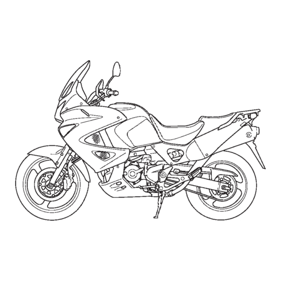
PARTS LOCATION Multi-function display Indicators Indicators Speedometer Tachometer Headlight dimmer switch Front brake fluid reservoir Choke lever Rearview mirror Rearview mirror Passing light Engine stop switch control switch Front brake lever Clutch lever Hazard warning Throttle grip system switch Turn signal switch Starter button Ignition switch Horn button... - Page 20 Oil filler cap Rear brake fluid reservoir Battery Fuel valve Coolant reserve Passenger footpeg tank Footpeg Rear suspension Brake pedal Oil level inspection spring preload adjuster window...
- Page 21 Storage compartment for U-shaped anti-theft lock Fuel valve Helmet holder Document compartment Gearshift pedal Footpeg Passenger footpeg Side stand...
-
Page 22: Instruments And Indicators
INSTRUMENTS AND INDICATORS The indicators are contained in the instrument panel. Their functions are described in the tables on the following pages. (1) Left turn signal indicator (2) Low oil pressure indicator (3) Fuel indicator (4) Multi-function display (5) Neutral indicator (6) PGM-FI indicator (7) Right turn signal indicator (8) Tachometer... - Page 23 Ref. No. Description Function Left turn signal indicator Flashes when the left turn signal operates or (green) hazard warning system operates. Lights when the engine oil pressure is below normal operating range. Should light when ignition switch is ON and engine is not running. Should go out when the engine starts, except for occasional flickering at or near idling speed when Low oil pressure indicator...
- Page 24 Ref. No. Description Function The display includes the following functions; Multi-function display This display shows the initial display (page 18). Coolant temperature gauge Shows coolant temperature (page 20). Odometer Shows accumulated mileage (page 21). Tripmeter Shows mileage per trip (page 23 ). Fuel mileage meter Shows fuel mileage (page 24).
- Page 25 (RUN). If it comes on at any other time , reduce speed and take the motorcycle to your Honda dealer as soon as possible. Right turn signal indicator Flashes when the right turn signal operates or (green) hazard warning system operates.
- Page 26 Ref. No. Description Function Tachometer Shows engine revolutions per minute. Never allow the tachometer needle to enter the red zone, even after the engine has been broken in. Tachometer red zone NOTICE Running the engine beyond recommended maximum engine speed (the beginning of the tachometer red zone) can damage the engine.
- Page 27 Ref. No. Description Function Use this button for the following purposes. • To adjust time Clock button • To switch blinking of the immobilizer system (HISS) indicator Use this button for the following purposes • To change indication of tripmeter A, tripmeter B and fuel mileage meter (Except E type: Trip button ‘‘km/l’’...
- Page 28 Ref. No. Description Function This indicator lights for a few seconds when the ignition switch is turned ON and the engine stop switch is at (RUN). It will then go off if the properly-coded key has been inserted. If an Immobilizer system (HISS) improperly-coded key has been inserted, the indicator (red)
- Page 29 Initial Display When the ignition switch is turned ON, the multi-function display (1) will temporarily show all the modes and digital segments so that you can make sure the liquid crystal display is functioning properly. The unit ‘‘mile’’ (2) and ‘‘mile/ l’’ (3) will be displayed only for E type.
- Page 30 Multi-function Display Multi-function display (1) includes the following functions: Coolant temperature gauge Odometer Tripmeter Digital clock Fuel mileage meter Digital clock (5) and tripmeter (3) will reset if the battery is disconnected. (1) Multi-function display (2) Odometer (3) Tripmeter/Fuel mileage meter (4) Coolant temperature gauge (5) Digital clock (6) Clock button...
- Page 31 Coolant Temperature Gauge Overheating Message When the coolant is over specif ied The coolant temperature gauge (1) shows temperature, the segment H (3) flashes. coolant temperature. If this occurs, stop the engine and check the reserve tank coolant level. Read When the segment C (2) goes on, the engine is warm enough for the motorcycle pages 33-34 and to not ride the...
- Page 32 Odometer Shows accumulated mileage. (1) Odometer...
- Page 33 Tripmeter/Fuel Mileage Meter To change the display of tripmeter and fuel mileage meter. For F, G, ED type The tripmeter/fuel mileage meter (1) has four functions: tripmeter A (2), tripmeter B (3), fuel mileage meter ‘‘km/l’’ (4) and fuel mileage meter ‘‘l/100 km’’ (5). P u s h t h e t r i p b u t t o n ( 6 ) t o s e l e c t t r i p m e t e r A , t r i p m e t e r B a n d f u e l mileage meter ‘‘mile/l’’...
- Page 34 Tripmeter (A and B) The tripmeter A (2) and tripmeter B (3) shows accumulated mileage. To reset the tripmeter A or tripmeter B, push and hold the trip button (6) with the display in the tripmeter A or tripmeter B. (2) Tripmeter A (3) Tripmeter B (6) Trip button...
- Page 35 Fuel Mileage Meter (‘‘km/l’’, ‘‘mile/l’’ and ‘‘l/100 km’’) Fuel mileage meter indicates the fuel mileage. The fuel mileage meter ‘‘km/l’’ (4) and fuel mileage meter ‘‘l/100 km’’ (5) is for F, G, ED type. The fuel mileage meter ‘‘mile/l’’ (7) is only for E type.
- Page 36 Digital clock 3. Push the clock button until the desired time is displayed. Shows hour and minute. To adjust the • The time is advanced by one minute, time, proceed as follows: each time the clock button is pushed. 1. Turn the ignition switch ON. •...
-
Page 37: Major Components
MAJOR COMPONENTS (Information you need to operate this motorcycle) SUSPENSION To adjust the adjuster to the standard position, proceed as follows : Rear Suspension 1. Turn the adjuster knob counterclockwise The spring preload adjuster has 36 until it will no longer turn. This is the full positions for different load or riding LOW position. - Page 38 Disposal should only be done by your Honda dealer. The instructions found in this owner’s manual are limited to adjustment of the shock assembly only.
- Page 39 Both the front and rear brakes are the system inspected for leaks. hydraulic disc types. As the brake pads wear, the brake fluid The recommended brake fluid is Honda level drops. There are no adjustments to perform, but DOT 4 brake fluid from a sealed fluid level and pad wear must be inspected container, or an equivalent.
- Page 40 Front Brake Lever: Other Checks: The distance between the tip of the brake Make sure there are no fluid leaks. Check lever (1) and the grip can be adjusted by for deterioration or cracks in the hoses turning the adjuster (2) while pushing the and fittings.
- Page 41 (page 118). Worn pads should be replaced. If the pads are not worn, have your brake system inspected for leaks. The recommended brake fluid is Honda DOT 4 brake fluid from a sealed container, or an equivalent. Other Checks: Make sure there are no fluid leaks.
- Page 42 CLUTCH 1. Pull back the rubber dust cover (2). Loosen the lock nut (3) and turn the Clutch adjustment may be required if the clutch cable adjuster (4). Tighten the motorcycle stalls when shifting into gear lock nut (3) and check the adjustment. or tends to creep;...
- Page 43 If proper adjustment cannot be obtained of the cable. Turn the adjusting nut (6) to or the clutch does not work correctly, see obtain the specified free play. Tighten your Honda dealer. the lock nut (5) and check the adjustment. Other Checks: 4.
- Page 44 COOLANT The factory provides a 50/50 solution of antifreeze and distilled water in this Coolant Recommendation motorcycle. This coolant solution is The owner must properly maintain the recommended f or most operat ing coolant to prevent freezing, overheating, temperatures provides good and corrosion.
- Page 45 Do not attempt to add coolant by removing the radiator cap. If the reserve tank is empty, or if coolant loss is excessive, check for leaks and see your Honda dealer for repair. (1) Reserve tank (4) Bolt (2) LOWER level mark...
- Page 46 FUEL Manual Fuel Valve The manual fuel valves (1) are under the both side of the fuel tank. Set it to ON all the time. The OFF setting is for long term storage, or servicing of fuel system components. (1) Fuel valves...
- Page 47 Fuel Tank The fuel tank capacity including the reserve supply is: 24.5 l (6.47 US gal , 5.39 Imp gal) To open the fuel fill cap (1), insert the ignition key (2) and turn it clockwise. The fuel fill cap is hinged and will lift up. Do not overfill the tank.
- Page 48 If spark knock or converters. pinking persists, consult your Honda dealer. Failure to do so is considered misuse, and damage caused by misuse is not covered...
- Page 49 Honda recommended by Honda. There are two types of ‘‘gasohol’’: one containing cannot endorse the use of fuels ethanol, and the other containing containing methanol since evidence of methanol.
-
Page 50: Engine Oil
ENGINE OIL 5. Reinstall the oil filler cap. Check for oil leaks. Engine Oil Level Check Check the engine oil level each day NOTICE before riding the motorcycle. Running the engine with insufficient oil The level must be maintained between the upper (1) and lower (2) level marks in the pressure may cause serious engine inspection window (3). -
Page 51: Air Pressure
TUBELESS TYRES Air Pressure To safely operate your motorcycle, your Keeping your tyres properly inflated tyres must be the proper type and size, in provides the best combination of good condition with adequate tread, and handling, tread life and riding comfort. correctly inflated for the load you are Generally, underinf lated tyres wear carrying. -
Page 52: Inspection
Always check air pressure when your Inspection tyres are ‘‘cold’’ when the motorcycle has Whenever you check the tyre pressures, been parked for at least three hours. If you should also examine the tyre treads you check air pressure when your tyres and sidewalls for wear, damage, and are ‘‘warm’’... - Page 53 Tread Wear Replace tyres before tread depth at the center of the tyre reaches the following limit: Minimum tread depth Front: 1.5 mm (0.06 in) Rear: 2.0 mm (0.08 in) <For Germany> German law prohibits use of tyres whose tread depth is less than 1.6 mm. (1) Wear indicator (2) Wear indicator location mark...
- Page 54 Tyre Repair Even if a tyre is professionally repaired If a tyre is punctured or damaged, you with a permanent internal patch plug, it should replace it, not repair it. As will not be as good as a new tyre. You discussed below, a tyre that is repaired, should not exceed 80 km/h (50 mph) for either temporarily or permanently, will...
- Page 55 Tyre Replacement The recommended tyres for your motorcycle are: The tyres that came on your motorcycle Front: 110/80 R19 59H were designed to match the performance 110/80 R19 M/C 59H capabilities of your motorcycle and BRIDGESTONE provide the best combination of handling, braking, durability and comfort.
- Page 56 Important Safety Reminders • Do not install a tube inside a tubeless tyre on this motorcycle. Excessive heat buildup can cause the tube to burst. • Use only tubeless tyres on this motorcycle. The rims are designed for tubeless tyres, during hard acceleration or braking, a tube-type tyre...
-
Page 57: Essential Individual Components Ignition Switch
ESSENTIAL INDIVIDUAL COMPONENTS IGNITION SWITCH The ignition switch (1) is below the indicator panel. The headlight, position light and taillights will come on whenever you turn the ignition switch ON. If your motorcycle is stopped with the ignition switch ON and the engine is not running, the headlight, position light and taillights will still be on, resulting in battery discharge. - Page 58 This motorcycle has two keys and a key safe place. number plate. To reproduce keys, bring all keys, key number plate and motorcycle to your Honda dealer. Up to four keys can be registered with the immobilizer system (HISS), including the ones in hand. (1) Keys...
- Page 59 If all keys are lost, the PGM-FI unit/ignition control module must be replaced. To avoid this possibility we recommend that if only one key is left, you immediately have it reproduced to ensure that a back-up is available. These keys contain electronic circuits that are activated by the immobilizer system (HISS).
-
Page 60: Immobilizer System (Hiss)
When the ignition switch is turned ON and the engine stop switch is at ‘‘ ’’ (RUN), HISS is the abbreviation of Honda Ignition the immobilizer system (HISS) indicator Security System. lights for a few seconds, then go off. If the... - Page 61 The immobilizer system has such a To alter the blinking function. function that keeps the immobilizer 1. Turn the ignition switch ON. system (HISS) indicator (1) blinking at 2 2. Turn the ignition switch OFF, push and second intervals for 24 hours. This hold the clock button for more than two blinking function can be turned on or off.
- Page 62 Directive is provided to the owner at the ignition control module must time of purchase. The declaration of replaced. conformity should be kept at a safe place. When the declaration of conformity is lost or is not provided, contact your Honda dealer.
-
Page 63: Right Handlebar Controls
RIGHT HANDLEBAR CONTROLS Starter Button The starter button (2) is below the engine Engine Stop Switch stop switch (1). The engine stop switch (1) is next to The starter button is used for starting the the throttle grip. When the switch is in engine. -
Page 64: Left Handlebar Controls
LEFT HANDLEBAR CONTROLS Headlight Dimmer Switch (1) Push the dimmer switch to (HI) to select high beam or to (LO) to select low beam. Passing Light Control Switch (2) When this switch is pressed, the headlight flashes on to signal approaching cars or when passing. - Page 65 Hazard Warning System Switch (5) This system should be used only when your motorcycle is stopped under emergency or hazardous conditions. To turn it on, turn the ignition key to the ON or ACC position, and then slide the switch ∆...
- Page 66 FEATURES (Not required for operation) STEERING LOCK To lock the steering, turn the handlebar all the way to the left, turn the key (1) to LOCK while pushing in. Remove the key. To unlock the steering, turn the key to OFF while pushing in.
- Page 67 SEAT To remove the seat (1), insert the ignition key (2) into the seat lock (3) and turn it clockwise. Pull the seat back and up. To install the seat, align the locating slot (4) under the front of the seat with the pin (5) on the rear of the fuel tank, and locating prongs (6) on the bottom of the seat with the hooks (7) on the frame, then...
-
Page 68: Helmet Holder
HELMET HOLDER The helmet holder is located below the seat. Remove the seat (page 56). Route the either end of the helmet holder wire (1) through the helmet’s D-ring (2). Hook the loops of the wire onto the helmet holder (3). Install the seat and lock it securely. -
Page 69: Windshield Height Adjustment
WINDSHIELD HEIGHT ADJUSTMENT The windshield (1) has two height positions: standard position and high position. To adjust the windshield height 1. Remove the windshield cover prongs (2) from the windshield holes (3). But do not remove the windshield cover (4) as shown. 2. - Page 70 1.0 N·m (0.1 kgf·m, 0.7 lbf·ft) 5. Install the windshield cover prongs to the windshield holes. If a torque wrench is not used for this installation, see your Honda dealer as soon as possible to verify proper assembly. (1) Windshield...
-
Page 71: Document Bag
DOCUMENT BAG The document bag (1) is in the document compartment (2) on the reverse side of the seat (3). This owner’s manual other documents should be stored in the document bag. When washing your motorcycle, be careful not to flood this area with water. (1) Document bag (2) Document compartment (3) Seat... - Page 72 STORAGE COMPARTMENT FOR U-SHAPED ANTI-THEFT LOCK The rear fender has a storage compartment to store a U-shaped anti-theft lock under the seat. After storing, be sure to fasten the lock with the rubber band (1) securely. Some U-shaped locks may not be stored in the compartment due to their size or design.
-
Page 73: Inner Cowl
INNER COWL Removal: 1. Remove the under cover (page 64). 2. Pull the clips (1) and remove the inner cowl (2). Installation: • Installation can be done in the reverse order of removal. (1) Clips (2) Inner cowl... -
Page 74: Under Cowl
UNDER COWL Removal: 1. Pull the clips (1). 2. Remove the bolts (2), collars (3), and under cowl (4). Installation: • Installation can be done in the reverse order of removal. (1) Clips (2) Bolts (3) Collars (4) Under cowl... -
Page 75: Under Cover
UNDER COVER Removal: 1. Pull the clips (1). 2. Remove the under cover (2). Installation: • Installation can be done in the reverse order of removal. (1) Clips (2) Under cover... - Page 76 UPPER COWL COVER Removal: 1. Pull the clips (1) and remove the bolts (2). 2. Remove the upper cowl cover (3). Installation: • Installation can be done in the reverse order of removal. (1) Clips (2) Bolts (3) Upper cowl cover...
-
Page 77: Fuel Tank Maintenance Position
FUEL TANK MAINTENANCE POSITION The rear of the fuel tank can be tilted up for maintenance. The fuel tank does not require draining. To raise: 1. Remove the seat (page 56). 2. Remove the tank bridge bar (page 88). 3. Remove the fuel tank mount bolts (1), washers (2) and fairing mount bolts (3). - Page 78 4. Remove the clips (5) from the upper 5. Raise the rear of the fuel tank (4) slightly cowl covers (6). and insert the tank bridge bar (7). (5) Clips (4) Fuel tank (6) Upper cowl covers (7) Tank bridge bar...
-
Page 79: Head/Light Aim Vertical Adjustment
HEAD/LIGHT AIM VERTICAL ADJUSTMENT Illustration shows right side, left side similar. Vertical adjustment can be made by turning the knob (1) in or out as necessary. Obey local laws and regulations. (1) Knob (A) Up (B) Down... - Page 80 If you detect any problem, be 4. Front and rear brakes—check operation; sure you take care of it, or have it make sure there is no brake fluid corrected by your Honda dealer. leakage (pages 28-30). ∆ WARNING Improperly...
- Page 81 5. Tyres—check condition and pressure (pages 40-45). 6. Drive chain—check condition and slack (page 101). Adjust and lubricate if necessary. 7. Throttle—check for smooth opening and full closing in all steering positions. 8. Lights and horn—check that headlight, tail/brake light, turn signals, indicators and horn function properly.
-
Page 82: Starting The Engine
STARTING THE ENGINE Your motorcycle’s exhaust contains Always follow the proper starting poisonous carbon monoxide gas. High procedure described below. levels of carbon monoxide can collect rapidly in enclosed areas such as a This motorcycle is equipped with a side stand ignition cut-off system. - Page 83 Preparation Starting Procedure Before starting, insert the key, turn the To restart a warm engine, follow the ignition switch ON and confirm the procedure for ‘‘High Air Temperature’’. following: • The transmission is in NEUTRAL Normal Air Temperature (neutral indicator light ON). 10°...
- Page 84 The engine will not start if the throttle is High Air Temperature fully open (because the electronic control 35°C (95°F) or above module cuts off the fuel supply). 1. Do not use the choke. 2. Start the engine. NOTICE Low Air Temperature Operating the engine with insufficient oil 10°C (50°F) or below pressure can cause serious engine...
- Page 85 Flooded Engine Ignition Cut Off If the engine fails to start after repeated Your motorcycle designed attempts, it may be flooded with excess automatically stop the engine and fuel fuel. pump if the motorcycle is over-turned (a To clear a flooded engine. banking sensor cuts off the ignition 1.
- Page 86 RUNNING-IN Help assure your motorcycle’s future reliability and performance by paying extra attention to how you ride during the first 500 km (300 miles). During this period, avoid full-throttle starts and rapid acceleration.
- Page 87 RIDING 1. After the engine has been warmed up, Review Motorcycle Safety (pages 1-7) the motorcycle is ready for riding. before you ride. 2. While the engine is idling, pull in the clutch lever and depress the gearshift Make sure you understand the function of the side stand mechanism.
- Page 88 5. Coordinate the throttle and brakes for smooth deceleration. 6. Both front and rear brakes should be used at the same time and should not be applied strongly enough to lock the wheel, or braking effectiveness will be reduced and control of the motorcycle be difficult.
- Page 89 BRAKING Important Safety Reminders: This motorcycle is equipped with a Dual Combined Brake System. Operating the • When possible, reduce speed or brake front brake lever applies the front brake before entering a turn; closing the and a portion of the rear brake. Operating throttle or braking in mid-turn may the rear brake pedal applies the rear cause wheel slip.
- Page 90 • When descending a long, steep grade, use engine compression braking by downshifting, with intermittent use of both brakes. Continuous brake application overheat the brakes and reduce their effectiveness. • Riding with your foot resting on the brake pedal or your hand on the brake lever may actuate the brakelight, giving a false indication to other drivers.
- Page 91 PARKING Make sure flammable materials such as 1. After stopping the motorcycle, shift the dry grass or leaves do not come in transmission into neutral, turn the contact with the exhaust system when handlebar fully to the left, turn the parking your motorcycle.
-
Page 92: Anti-Theft Tips
ANTI-THEFT TIPS 1. Always lock the steering and never leave the key in the ignition switch. This NAME: sounds simple but people do forget. 2. Be sure the registration information for ADDRESS: your motorcycle is accurate and current. 3. Park your motorcycle in a locked garage whenever possible. - Page 93 MAINTENANCE If your motorcycle overturns or becomes THE IMPORTANCE OF MAINTENANCE involved in a crash, be sure your Honda A well-maintained motorcycle is essential dealer inspects all major parts, even if you for safe, economical and trouble-free riding. are able to make some repairs.
-
Page 94: Maintenance Safety
Always follow the procedures and by professionals. Wheel removal should precautions in this owner’s manual. normally be handled only by a Honda technician or other qualified mechanic; instructions are included in this manual only to assist in emergency service. -
Page 95: Safety Precautions
• Injury from moving parts. Do not run the engine unless To ensure the best quality and reliability, instructed to do so. use only new genuine Honda parts or • Read the instructions before you begin, their equivalents repair replacement. -
Page 96: Maintenance Schedule
Honda by properly trained and equipped technicians. Your Honda dealer meets all of these requirements. Should be serviced by your Honda dealer, unless the owner has the proper tools and service data and is mechanically qualified. Refer to the Official Honda Shop Manual. - Page 97 WHICHEVER ODOMETER READING [(NOTE (1)] FREQUENCY COMES x 1,000 km FIRST Refer x 1,000 mi 12 16 20 24 ITEM page NOTE MONTH FUEL LINE — THROTTLE OPERATION CHOKE OPERATION — AIR CLEANER (NOTE 2) — SPARK PLUGS EVERY 24,000 km (16,000 mi) I, 95-97 EVERY 48,000 km (32,000 mi) R VALVE CLEARANCE...
- Page 98 WHICHEVER ODOMETER READING [(NOTE (1)] FREQUENCY COMES x 1,000 km FIRST Refer x 1,000 mi 12 16 20 24 ITEM page NOTE MONTH DRIVE CHAIN I, L EVERY 1,000 km (600 mi) DRIVE CHAIN SLIDER BRAKE FLUID (NOTE 3) BRAKE PAD WEAR BRAKE SYSTEM BRAKE LIGHT SWITCH HEADLIGHT AIM...
- Page 99 TOOL KIT The tool kit (1) is under the seat (page 56). Some roadside repairs, minor adjustments and parts replacement can be performed with the tools contained in the kit. • Helmet holder wire • Spark plug wrench • 10 x 12 mm Box end wrench •...
-
Page 100: Serial Numbers
SERIAL NUMBERS The frame number (1) is stamped on the The frame and engine serial numbers are right side of the steering head. required when registering your motorcycle. They may also be required by your dealer The engine number (2) is stamped on top when ordering replacement parts. -
Page 101: Colour Label
COLOUR LABEL The colour label (1) is attached to the frame behind the left side cover. It is helpful when ordering replacement parts. Record the colour and code here for your reference. COLOUR CODE (1) Colour label... - Page 102 ENGINE OIL Refer to the Safety Precautions on page Engine Oil Good engine oil has many desirable qualities. Use only high detergent, quality motor oil certified on the container to meet or exceed requirements for API Service Classification SE, SF or SG. Viscosity: Viscosity grade of engine oil should be based...
- Page 103 Honda dealer perform this service. Please dispose of used engine oil in a manner that is compatible with the If a torque wrench is not used for this environment.
- Page 104 1. To drain the oil, remove the oil filler cap 3. Remove the oil filter (3) with a filter and oil drain plug (1) and sealing washer wrench and let the remaining oil drain (2). out. 2. Remove the under cowl (page 63). Discard the oil filter.
- Page 105 26 N·m (2.7 kgf·m, 20 lbf·ft) Oil Drain Plug Torque: 30 N·m (3.1 kgf·m , 22 lbf·ft) Use only the Honda genuine oil filter or a 7. Fill the crankcase with the recommended filter of equivalent quality specified for grade oil; approximately: your model.
-
Page 106: Spark Plugs
SPARK PLUGS This motorcycle uses the spark plugs that have a iridium coated center electrode. Refer to the Safety Precautions on page Be sure to observe the following when servicing the spark plugs. Recommended plugs: IJR8B9 (NGK) • Do not clean the spark plug. If the elect rode is contaminated wi th accumulated NOTICE objects or dirt, replace the spark plug... - Page 107 1. To remove the spark plug from the rear 2. Disconnect the spark plug caps from the cylinder, raise the fuel tank (page 66). spark plugs. 3. Clean any dirt from around the spark Rear cylinder plug bases. Remove the spark plugs using the spark plugwrench (1) furnished in the tool kit.
- Page 108 5. Make sure that the 1.0 mm wire-type 6. Make sure the plug washer is in good feeler gauge does not insert between condition. the spark plug gap (2). If the gauge is 7. With the plug washer attached, thread inserted into the gap, replace the plug the spark plug in by hand to prevent with a new one.
-
Page 109: Throttle Operation
THROTTLE OPERATION Refer to the Safety Precautions on page 1. Check for smooth rotation of the throttle grip from the fully open to the fully closed position at both full steering positions. 2. Measure the throttle grip free play at the throttle grip flange. -
Page 110: Idle Speed
IDLE SPEED Refer to the Safety Precautions on page The engine must be at normal operating temperature for accurate idle speed adjustment. Ten minutes of stop-and-go riding is sufficient. 1. Warm up the engine, and shift to neutral, and place the motorcycle on its side stand. - Page 111 Coolant Replacement spray out, seriously scalding you. Coolant should be replaced by a Honda dealer, unless the owner has proper tools Always let the engine and radiator and service data and is mechanically cool down before removing the qualified.
-
Page 112: Drive Chain
DRIVE CHAIN Drive chain slack should be adjusted to allow the following vertical movement by Refer to the Safety Precautions on page hand: 35-45 mm(1.4-1.8 in) 3. Roll the motorcycle forward. Stop. The service life of the drive chain is dependent upon proper lubrication and Check the drive chain slack. - Page 113 Damaged sprocket Worn sprocket 4. Roll the motorcycle forward. Stop and Teeth Teeth place it on its side stand. Inspect the drive chain and sprockets for any of the Replace Replace following conditions: DRIVE CHAIN • Damaged Rollers • Loose Pins •...
- Page 114 Adjustment: If the drive chain requires adjustment, the Drive chain slack should be checked and procedure is as follows: adjusted, if necessary, every 1,000 km 1. Place the motorcycle on its side stand (600 miles). When operated at sustained with the transmission in neutral and the high speeds or under conditions of ignition switch off.
- Page 115 5. Tighten the axle nut to specified torque. Axle nut torque: 93 N·m (9.5 kgf·m, 69 lbf·ft) If a torque wrench is not used for this installation, see your Honda dealer as soon as possible to verify proper assembly. 6. Tighten the adjusting bolts lightly.
- Page 116 RK525 ROZ1 This motorcycle has a staked master link drive chain which requires a special tool for cutting and staking. Do not use an (5) Index mark ordinary master link with this chain. See (6) Red zone your Honda dealer.
- Page 117 Lubrication and Cleaning: Lubricate every 1,000 km (600 miles) or sooner if chain appears dry. The drive chain on this motorcycle is equipped with small O-rings between the link plates. These O-rings retain grease inside the chain to improve its service life. The O-rings in this chain can be damaged by steam cleaning, high pressure washers, and certain solvents.
-
Page 118: Drive Chain Slider
Refer to the Safety Precautions on page Check the chain slider (1) for wear. The chain slider must be replaced if it is worn to the wear limit line (2). For replacement, see your Honda dealer. (1) Chain slider (2) Wear limit line... -
Page 119: Front And Rear Suspension Inspection
FRONT AND REAR SUSPENSION INSPECTION Refer to the Safety Precautions on page 1. Check the fork assembly by locking the front brake and pumping the fork up and down vigorously. Suspension action should be smooth and there must be no oil leakage. -
Page 120: Side Stand
SIDE STAND If the side stand system does not operate Refer to the Safety Precautions on page as described, see your Honda dealer for service. Perform the following maintenance in accordance with the maintenance schedule. Functional Check: • Check the spring (1) for damage or loss of tension and the side stand assembly for freedom of movement. -
Page 121: Wheel Removal
WHEEL REMOVAL 3. Remove the socket bolt A (2) and socket Refer to the Safety Precautions on page bolt B (3). Front Wheel Removal 1. Raise the front wheel off the ground by placing a support block under the engine. 2. - Page 122 If this occurs, servicing of the brake doesn’t hang from the hose. Do not twist system will be necessary. See your the brake hose. Honda dealer for this service. (5) Right caliper assembly (4) Left caliper assembly (6) Fixing bolts...
- Page 123 6. Loosen the right and left axle pinch bolts (7), and remove the axle bolt (8). 7. Withdraw the front axle (9) and remove the front wheel. (7) Axle pinch bolts (9) Front axle (8) Axle bolt...
- Page 124 Installation: 4. Install the right and left caliper assembly 1. Position the front wheel between the to the fork legs, tighten the fixing bolts fork legs and insert the front axle from and socket bolts to the specified torque: the left side, through the left fork leg and 31 N·m (3.2 kgf·m, 23 lbf·ft) wheel hub.
- Page 125 7. Measure the clearance (10) between each surface of the left brake disc (11) and the left brake caliper holder (12) (not brake pads) with a 0.7 mm (0.028 in) feeler gauge (13) (see illustration). (10) Clearance (13) Feeler gauge (11) Brake disc (12) Caliper holder...
- Page 126 If the torque wrench was not used for released. Recheck the wheel if the installation, see your Honda dealer as brake drags or if the wheel does not soon as possible to verify proper rotate freely.
- Page 127 If this occurs, servicing of the brake system will be necessary. See your Honda dealer for this service. (1) Adjusting bolts (3) Axle shaft (2) Drive chain (4) Rear axle nut...
- Page 128 Installation Notes: If a torque wrench was not used for • To install the rear wheel, reverse the installation, see your Honda dealer as removal procedure. soon as possible to verify proper • Make sure that the slot (5) on the brake assembly.
-
Page 129: Brake Pad Wear
<REAR BRAKE> Check the cutout (1) in each pad. If either pad is worn to the cutout, replace both pads as a set. See your Honda dealer for this service. Rear Brake Check the cutout (2) in each pad. -
Page 130: Brake System Inspection
Refer to the Safety Precautions on page tip of the secondary master cylinder (2). If the stroke (3) exceeds 4.0 mm (0.16 in), see your Honda dealer. Check the brake system as follows: 1. Place the motorcycle on its side stand,... - Page 131 (causing hard starting Wear protective clothing and a face or other electrical troubles), contact your shield, or have a skilled mechanic do Honda dealer. the battery maintenance. NOTICE Your battery is a maintenance-free type and can be permanently damaged if the...
- Page 132 Battery Removal 1.Remove the seat (page 56). 2. Release the rings and remove the rubber band (1). 3. Disconnect the negative (-) terminal lead (2) from the battery first, then disconnect the positive (+) terminal lead (3). 4. Pull out the battery (4) from the battery box.
-
Page 133: Fuse Replacement
Blown fuse When frequent fuse failure occurs, it usually indicates a short circuit or an overload in the electrical system. See your Honda dealer for repair. NOTICE Never use a fuse with a different rating from that specified. Serious damage to... - Page 134 Fuse Box: The fuse box is located under the seat. The specified fuses are: 10A, 20A 1. Remove the seat (page 56). 2. Open the fuse box cover (1). 3. Pull out the old fuse and install a new fuse. The spare fuses (2) are located in the fuse box.
- Page 135 Main Fuse: The main fuse (1) is located under the seat. The specified fuse is: 1. Remove the seat (page 56). 2. Disconnect the wire connector (2) of the starter magnetic switch. 3. Pull out the old fuse and install a new fuse.
-
Page 136: Stoplight Switch Adjustment
STOPLIGHT SWITCH ADJUSTMENT Refer to the Safety Precautions on page Check the operation of the stoplight switch (1) at the right side behind the engine from time to time. Adjustment is done by turning the adjusting nut (2). Turn the nut in the direction (A) if the switch operates too late and in direction (B) if the switch operates too soon. -
Page 137: Bulb Replacement
BULB REPLACEMENT • Be sure to turn the ignition switch OFF Refer to the Safety Precautions on page when replacing the bulb. • Do not use bulbs other than that specified. The light bulb becomes very hot while the light is ON, and remain hot for a while •... - Page 138 Headlight Bulb 1. Remove the upper cowl cover (page 65). 2.Pull out the socket (1) without turning. 3. Remove the dust cover (2). 4. Remove the bulb (4) while pressing down on the pin (3). 5. Pull out the bulb (4) without turning. 6.
- Page 139 Position Light Bulb 1. Remove the under cover (page 64). 2. Pull the position light socket (1) and remove it. 3. Pull out the bulb (2) without turning. 4. Install a new bulb in the reverse order of removal. (1) Position light socket (2) Bulb...
- Page 140 Stop/Taillight Bulb 1. Remove the seat (page 56). 2. Turn the socket (1) approximately 45° counterclockwise, then pull it out toward you. 3. Slightly press the bulb (2) and turn it counterclockwise. 4. Install a new bulb in the reverse order of removal.
- Page 141 Front Turn Signal Bulb 1. Remove the under cover (page 64) and inner cowl (page 62). 2. Turn the socket (1) counterclockwise and remove it. 3. Slightly press the bulb (2) and turn it counterclockwise. 4. Install a new bulb in the reverse order of removal.
- Page 142 Rear Turn Signal Bulb 1. Remove the rear turn signal lens (1) and the lens packing (2) by removing the screw (3). 2. Slightly press the bulb (4) and turn it counterclockwise. 3. Install a new bulb in the reverse order of removal.
- Page 143 License Light Bulb 2. Remove the license light cover (4) and 1. Remove the two bolts (1) and remove license light lens (5) by removing the two the license light assembly (2). nuts (3). 3. Slightly press the bulb (6) and turn it counterclockwise.
- Page 144 CLEANING Washing the motorcycle Clean your motorcycle regularly to protect 1. Rinse the motorcycle thoroughly with cool water to remove loose dirt. the surface finishes and inspect for 2. Clean the motorcycle with a sponge or damage, wear, and oil, coolant or brake fluid leakage.
- Page 145 7. Lubricate the drive chain immediately If a surface on your motorcycle is chipped after washing and drying the motorcycle. or scratched, your Honda dealer has touchup paint to match your motorcycle’s Braking efficiency may be temporarily colour. impaired immediately after washing the Be sure to use your motorcycle’s colour...
- Page 146 Removing Road Salt Painted Aluminum Wheel Maintenance The salt contained in the road surface Aluminum may corrode from contact with freezing prevention medicine which a dirt, mud, or road salt. Clean the wheels road was sprayed with in winter, and the af ter riding through any of these seawater becomes the cause which rust substances.
- Page 147 Clean The Windshield Take care to keep battery electrolyte, brake fluid or other chemical solvents off Using plenty of water, clean the the windshield and screen garnish. They windshield with a soft cloth or sponge. will damage the plastic. (Avoid using detergents or any kind of chemical cleaner on the windshield.) Dry with a soft, clean cloth.
-
Page 148: Storage Guide
∆ STORAGE GUIDE WARNING Extended storage, such as for winter, requires that you take certain steps to Petrol is highly flammable and reduce the effects of deterioration from explosive. You can be burned or non-use of the motorcycle. In addition, seriously injured when handling fuel. - Page 149 4. To prevent rusting in the cylinders, 5. Remove the battery. Store in an area perform the following: protected from freezing temperatures • Remove the spark plug caps from the and direct sunlight. spark plugs. Using tape or string, Slow charge the battery once a month. secure the caps to any convenient 6.
-
Page 150: Removal From Storage
REMOVAL FROM STORAGE 1. Uncover and clean the motorcycle. Change the engine oil if more than 4 months have passed since the start of storage. 2. Charge the battery as required. Install the battery. 3. Drain any excess aerosol rust-inhibiting oil from the fuel tank. -
Page 151: Specifications & Dimensions
SPECIFICATIONS DIMENSIONS Overall length 2,292 mm (90.2 in) Overall width 924 mm (36.4 in) Overall height 1,465 mm (57.7 in)…(Extra lowest) 1,509 mm (59.4 in)…(Extra highest) Wheelbase 1,559 mm (61.4 in) WEIGHT Dry weight 245 kg (540 lbs) CAPACITIES Engine oil After draining 3.4 l (3.6 US qt, 3.0 Imp qt) After draining and oil filter change... - Page 152 ENGINE Bore and stroke 98.0 x 66.0 mm (3.90 x 2.60 in) Compression ratio 9.8 : 1 Displacement 996 cm (60.8 cu-in) Spark plug IJR8B9 (NGK) Idle speed 1,200 ± 100 min (rpm) Valve clearance (Cold) Intake 0.16 mm (0.006 in) Exhaust 0.31 mm (0.012 in)
-
Page 153: Chassis And Suspension
CHASSIS AND SUSPENSION Caster 27° 30’ Trail 110 mm (4.3 in) Tyre size, front 110/80 R19 59H or 110/80 R19 M/C 59H Tyre size, rear 150/70 R17 69H or 150/70 R17 M/C 69H POWER TRANSMISSION Primary reduction 1.682 Gear ratio, 2.571 1.684 1.292... - Page 154 ELECTRICAL Battery 12V-18AH Generator 0.434 kW/5,000 min LIGHTS Headlight 12V-60/55W x 2 Brake/taillight 12V-21/5W x 2 Turn signal light Front 12V-21W Rear 12V-21W License light 12V-5W Position light 12V-5W FUSE Main fuse Other fuses 10A, 20A...
-
Page 155: Catalytic Converters
The catalytic converters act on HC, CO, contaminate the catalyst metals, making and NOx. Replacement parts must be the catalytic converters ineffective. original Honda parts or equivalents. • Keep the engine tuned-up. The catalytic converters must operate at a high temperature for the chemical •...
Need help?
Do you have a question about the XL1000V Varadero and is the answer not in the manual?
Questions and answers