Table of Contents
Advertisement
Quick Links
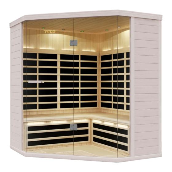
3 – 4 person infrared sauna
Note: The cabin must be installed on a flat, level surface.
Precautions to be taken before commissioning
Pre-assembly information
Electrical requirements
Cabin construction/ assembly
Junction box connections
Main junction box connections
Power connections on the ceiling
Control panel instructions
Lighting: Internal/ external/ colour therapy
Maintenance & technical support
Wiring diagram
Prime+ 1515/C
User Manual
Page 1
121210
2
2
2
3
3
7
9
12
12
13
14
Advertisement
Table of Contents

Subscribe to Our Youtube Channel
Related Manuals for Tylo Prime+ 1515/C


Summary of Contents for Tylo Prime+ 1515/C
- Page 1 121210 3 – 4 person infrared sauna Prime+ 1515/C User Manual Note: The cabin must be installed on a flat, level surface. Precautions to be taken before commissioning Pre-assembly information Electrical requirements Cabin construction/ assembly Junction box connections Main junction box connections...
-
Page 2: Precautions To Be Taken Before Commissioning
Precautions to be taken before commissioning Warning (space configuration and use): • Correct electrical earthing is required • Electrical sockets are not permitted in the sauna. • Do not allow heating elements to come into contact with water. • Do not fit a lock or bolt on the door. •... - Page 3 How to construct the sauna: Note – there are (14) power connections inside the sauna. (10) are in the sauna: left and right rear wall panels, left and right front, wall panels, left and right bench valance, fan, left and right bench and main power connection There are additional power connections on the top outer face of the ceiling.
- Page 4 Floor panel ( 1): Put the floor panel on a level surface 8-16 cm from the wall panel and no more than 152 cm away from a 230V socket. Position the floor panel in such a way that the slot for the glass sections are at the front of the sauna. Note: Put the ceiling, bench valance and bench aside until the corresponding steps.
- Page 5 Left side wall panel ( • Place the left wall panel section into the left hand slot on the floor panel. • Attach the left wall panel to the back wall panel by lifting the left panel and pushing it into the retaining bracket on the back panel. •...
- Page 6 Left bench valance ( • Insert the bench valance between the left and right wall panel sections. • Connect the S-3 electrical supply to the S-3 junction box. • Fix the cover of the S-3 junction box with 2 Phillips screws. Slide the fan component ( 1) into the retaining bracket on the bench valance.
-
Page 7: Main Junction Box Connections
Black main junction box: Connections Locate the black main junction box that is fixed to the internal floor of the sauna. Insert the 24 pin, multicoloured cable plug into the left hand side of the main junction box. See point 3 - Input/output The ON/ OFF switch is on the right hand side of the main junction box. - Page 8 Short bench ( • Rest the bench upright against the back wall panel. • Connect the S-2 electrical supply to the S-2 junction box. • Fix the cover of the S-2 junction box with 2 Phillips screws. Lay the bench down and push first the right hand and then the left hand edge into position. •...
- Page 9 Ceiling: • Lift the ceiling up and place it carefully on the five (5) panels as shown below. • Note: Ensure that the (3) electrical connections – 1 on the front panel and 2 on the rear left panel – are placed through the ceiling and are not disconnected when you put the ceiling into position slowly.
- Page 10 Ceiling to the rear panel: (4) connections: Lift the door panel on the top left of the rear external face of the ceiling. You will see 4 connections labelled 1–4. Fix each ceiling connection 1–4 to the corresponding number. Ensure that they are connected securely to each other. After connecting (4) close the ceiling flap.
- Page 11 De luxe door handles: Inside Outside Your infrared sauna is now ready for use. ------------------------------------------------------------------------------------------------------------------------------------------------ Page 11...
-
Page 12: Control Panel Instructions
Control panel instructions: Main current: Press POWER to turn the sauna ON (AN) or OFF (AUS). If a red light comes on the sauna is ON. If it is white the sauna is OFF. Timer functions: Press and hold down in order to set the running time. -
Page 13: Troubleshooting Tips
4. Press – BLUE-GREEN 5. Press – BLUE 6. Press – BLUE-RED 7. Press – BLUE-RED-GREEN 8. Press – Activates the full rotation of all the 7 aforementioned colour therapies one after the other. 9. Press – Turns the colour therapy functions OFF. Note: The colour of the light is indicated by the waves around the bulb symbol. -
Page 14: Wiring Diagram
Wiring Diagram Page 14...
Need help?
Do you have a question about the Prime+ 1515/C and is the answer not in the manual?
Questions and answers