
Related Manuals for Superabrasive LAVINA 30G-X


Summary of Contents for Superabrasive LAVINA 30G-X
- Page 1 LAVINA 30G-X User Manual ® Tech Support Line: 800-987-8403 | www.superabrasive.com | info@superabrasive.us ...
- Page 2 Superabrasive User Manual Original Language Lavina® 30G‐X 6/2017 2 ...
-
Page 3: Warranty And Returns
WARRANTY POLICY FOR LAVINA X MACHINES A warranty card must be submitted to Superabrasive within 30 days of purchase in order for the foregoing warranty to apply. You can either mail a hard copy of the warranty card or submit it electronically - see page 2. -
Page 4: Table Of Contents
Superabrasive User Manual Original Language Lavina® 30G‐X 6/2017 6. Popular Tools .............. 16 Warranty And Returns ............. 3 7.Maintenance And Inspection .......... 17 1. General Information ............ 5 Remark ................ 17 Mechanical Parts ............... 17 Manufacturer .............. 5 Cleaning ................ 17 General Description ............. 5 Check Hourly .............. 17 Machine Characteristics ............ 5 Check Daily ................ 17 Lavina® 30G‐X Main Design .......... 5 Check And Replace After The First 8 Working Hours .. 17 Environmental Conditions ........... 6 Check And Replace Every 50 Working Hours .... 17 Vacuum Connection ............ 6 Check And Replace Every 200 Working Hours .... 18 Technical Data .............. 6 Check And Replace Every 400 Working Hours .... 18 ... -
Page 5: General Information
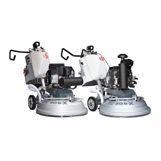
Superabrasive User Manual Original Language Lavina® 30G‐X 6/2017 1. GENERAL INFORMATION This owner’s manual is intended for the operator of the Lavina® X machine, the servicing technician as well as for anyone involved with operating or servicing the machine. We recommend that you read the instructions very carefully and follow them strictly. The manual includes information about assembling, using, handling, adjusting and maintaining your Lavina® X floor grinding and polishing machine. MANUFACTURER Superabrasive was founded in 1987, as a manufacturer of high quality diamond tools for the stone and concrete industry. Today, Superabrasive is one of the world’s leading companies in the production of diamond tools and floor grinding machinery. At Superabrasive, we strive to deliver the very best solutions to our customers, and enable them to work more efficiently. GENERAL DESCRIPTION The Lavina® X machine is intended for grinding, polishing and buffing concrete, marble, granite, limestone and terrazzo surfaces with diamond tools. Additionally, the machine could be used for grinding wood floor surfaces. The Lavina® X machine is a three‐disc machine, which can be used wet or dry. For best results, use only tools manufactured or recommended by Superabrasive and its distributors. The Lavina® X machine is manufactured and fitted for the above‐mentioned applications only! Every other use may possess risks to the persons involved. MACHINE CHARACTERISTICS The Lavina® X machine is made of two main component sections: LAVINA® 30G‐X MAIN DESIGN The two main components are the carriage and main head. The handle on the frame is adjustable in height and allows the operator to work in a Figure 1.1 correct and safe posture. ... -
Page 6: Environmental Conditions
The sonorous emissions are within the limits of directives and harmonized standards from the European Union when the Lavina® X is operated with the recommended tools and in normal conditions. However, the operator must wear ear protectors. LABEL DATA The data on the label provides the correct Voltage and Power (kW) (needed for operational purposes); Weight (needed for transportation purposes); production year and serial number (needed for maintenance purposes). CUSTOMER SERVICE For customer assistance and technical support call your local distributor or call Superabrasive Inc. at 1‐800‐987‐8403 or visit us at: w ww.superabrasive.com , where you can download a copy of this manual . ... -
Page 7: Safety Instructions
Superabrasive User Manual Original Language Lavina® 30G‐X 6/2017 2. SAFETY INSTRUCTIONS RECOMMENDED USE The LAVINA® 30G‐X machine is designed and manufactured to SAFE USE The LAVINA® 30GX is designed to reduce all risks correlated grind and polish concrete, terrazzo and natural stone floors. It can with its use. However, it is not possible to fully eliminate the be used for renovations as well as for polishing. The machine is designed for dry or wet use. When using it dry, use a vacuum of risks of an accident with the machine. Unskilled appropriate size. For more information, please refer to the chapter or uninstructed operator may cause correlated residual risks. Such risks are: on handling the vacuum connection. - Position Risks due to operator’s incorrect working position - Entanglement Risks due to wearing inappropriate working PROHIBITED USE The machine MUST NOT be used: ... -
Page 8: Hazard Communication
Superabrasive User Manual Original Language Lavina® 30G‐X 6/2017 Carbon monoxide is an invisible, odorless, colorless gas the public,” Onyx Environmental Solutions suggests usage when created when fossil fuels (such as gasoline, wood, coal, occupancy of a given work area is minimal. CARB / EPA propane, oil and methane) burn incompletely . The California Air Resource Board (CARB) and Environmental HAZARD COMMUNICATION Protection Agency (EPA) also set limits for propane‐powered A Material Safety Data Sheet for propane is to be posted engines used outdoors, but CARB/EPA approval does not signify that in all buildings where propane will be used. the engine is safe to use indoors. Because propane is odorized, it is easily detected at levels CGA of just a few parts per million, which is far below than the The Canadian Gas Association (CGA) has set a limit of 1500 ppm exposure limit of 1000 parts per million. CO in exhaust flow. If you smell propane while operating a propane floor OSHA care machine, do the following: For propane powered machines used indoors, the Occupational Stop the engine: Health and Safety Administration (OSHA) has established a limit of 50 1. Pull the throttle to the stop position (if present) or ... -
Page 9: Operating Machine
Superabrasive User Manual Original Language Lavina® 30G‐X 6/2017 OPERATING MACHINE Drager. SENSIDYNE gas sampling system with YB‐11038 When operating the Lavina® 30G‐X, make certain Sensidyne dectector tubes that there is no one, but you around the machine. Never leave the machine unattended while working. DRAGER gas sampling system with YB‐4620 Drager The water hose must move freely and must be damage‐ detective tubes GAS‐TECH Model CO‐95 free. Make sure the working surface is not too uneven. If it is, it ENERAC POCKET 60: Manufactured by Energy Efficiency System may damage the machine. 2) ENGINE EXHUAST ANALYZERS HORIBA AFTER WORK IS COMPLETED GAS ANALYZER Clean the machine and its ENERAC 2000 COMBUSTION ANALYZER surroundings properly Empty and clean the water tank ENERAC POCKET 60 ... -
Page 10: Refuelling Cylinders
Superabrasive User Manual Original Language Lavina® 30G‐X 6/2017 the common 20‐lb propane outdoor grill cylinders (which STORAGE CYLINDERS are not legal for use on propane floor machines), the motor fuel cylinder has a number of safety systems When not in use, propane cylinders always should be stored designed into it to ensure your safety at all times. outside in an upright position in a secure, tamperproof, steel There are two types of 20 lb. motor fuel cylinders. mesh storage cabinet. This cabinet may be located next to the building but with at least five Liquid draw feet (1.5 m) of space between the cabinet and the nearest Vapor draw The liquid draw cylinder is used on larger vehicles like building opening (door or window), and away from heat and direct sunlight. forklifts. These machines have special vaporizing Do not install the cabinet near a stairway or street elevator as carburetors to allow the propane to change from a liquid vented propane gas will seek a lower level since it is heavier than to a gas before being burned in the combustion chamber. The vapor draw cylinder is used on small machines like the air and could find its way into the basement of the building. Do not store cylinders full or empty inside a building or inside a propane powered floor care machines. The vacuum ... -
Page 11: Handling And Transportation
Superabrasive User Manual Original Language Lavina® 30G‐X 7/2017 3. HANDLING AND TRANSPORTATION ADJUSTING THE HANDLE The Handle on the frame is adjustable in height and allows the operator to work in a correct and safe posture (Fig. 3.1, Fig. 3.2). Choose the vertical position to move easy the machine (Fig.3.2). Figure 3.1 Figure 3.1.1 To adjust, simply pull the locking pin (Fig.3.1) and move the frame. A loaded spring will return the pin and lock the handle in any of several positions (Fig.3.1.1). To avoid turning the head during transport unscrew the butterfly, wing‐headed screw and move the lever from pos.3.3a to pos.3.3.b Figure 3.2.2 The lever must be in the position shown in Fig.3.3a when the machine is running, as well as to rotate the head when Figure 3.3b Figure 3.2 Figure 3.3a changing the tool. LIFTING THE MACHINE FROM WORKING TO TOOL MOUNTING POSITION Push the pin on the front handle down and ... -
Page 12: Storage
Superabrasive User Manual Original Language Lavina® 30G‐X 7/2017 STORAGE Always store and transport the LAVINA® X machine in a dry place. Never transport the LAVINA® X machine unprotected; it may be damaged if transported unprotected during rain or snow. When, during storage of the machine, the temperature may fall to 32F (or 0 o C) or less, water should be emptied from the system using the following steps: ‐ Pull the hose out of the tank (Fig.3.7) ‐ Using compressed air, blow out excess water from the system for each position of the lever (Fig. 3.8, Fig. 3.9). Figure 3.9 Figure 3.8 Figure 3.7 MOUNTING OF GUARD ASSEMBLY ... -
Page 13: Operation
Superabrasive User Manual Original Language Lavina® 30G‐X 7/2017 4. OPERATION Preliminary Controls Inspect the working area as explained in the safety instructions. Fill in the water tank for wet use or connect the vacuum extractor and ensure that the vacuum hose is clear and it will follow the machine easily. Make sure the bonnet air filter on top of the engine is clean. It should be cleaned hourly. Check the engine oil level, screw the dipstick in to get reading. Make sure the tank is full (see also “Storage Propane tanks). TANK and FUEL LINES ‐ Check the tank and fuel lines for any sign of wear and tear, such as cracks or any corrosion. Screw the brass fuel line fitting onto the tank service‐valve (hand tight only). This connection MUST be secure because the service valve has a safety valve inside it, which will only open if the brass fuel‐line fitting is COMPLETELY seated into the service valve. WATER FLOW CONTROL UNIT The operator can direct water to be sprayed in the front (Fig.4.1) by positioning the lever in the horizontal position; the water will spray under the cover of the machine when the lever is in the vertical position (Fig.4.2). The flow regulating valve located on the tank (Fig.4.3) controls the water flow to the working area – in front of the machine or under the main head cover of the machine. Figure 4.1 Figure 4.2... -
Page 14: Control Board
Superabrasive User Manual Original Language Lavina® 30G‐X 7/2017 CONTROL BOARD pm engine rpm tools THE CONTROL BOARD 2000 570 1 Start/Stop Engine switch Turn key fully to the 2100 600 right (make contact) to ignite the engine. Fully to 2200 630 the left will arrest the engine. 2300 660 2 Start/Stop clutch Start will electronically 2400 690 activate the grinding plates to spin; stop will 2500 715 disconnect engine from grinding heads 2600 745 3 Throttle Push forward to accelerate. 2700 4 Digital Tachometer/workings hours indicator 2800 800 When running, it indicates the revolutions per 2900 830 ... -
Page 15: Tools And Accessories
Superabrasive User Manual Original Language Lavina® 30G‐X 7/2017 5. TOOLS AND ACCESSORIES WEIGHTS Superabrasive offers additional weights used to increase the productivity of the machine (Fig.5.1). Each additional weight weighs about 64 lbs or 29kg. Each individual application, type and condition of surface, power capacity of the outlet, etc. will determine the number of weights you can use without tripping a breaker. The weights stack onto three posts fixed around the outer bowl (Fig.5.2). Additional weights will largely depend on the tools; it is not always possible to add weights. Some tools work too aggressively and will cause the machine to stop. The weight can be ordered with Figure 5.1 item number A08.00.00.00 Figure 5.2 TOOL HOLDER KEY The tool holder key (Fig. 5.3) is used for adjusting, mounting and dismounting of ... -
Page 16: Popular Tools
Superabrasive User Manual Original Language Lavina® 30G‐X 7/2017 6. POPULAR TOOLS QuickChange System and Tooling feature extremely fast and convenient tool changes, and a long tool life, providing for great long‐term cost savings. The QuickChange pads are produced in four different bonds for super hard, hard, medium and soft concrete, in a variety of grit sizes. They are offered with 1 or 2 buttons or rectangular segments, which allows you to customize the aggressiveness of the cut. Calibra grinding discs: our popular ceramic bond discs are designed for the removal of difficult scratches and they save you valuable time by eliminating the need for multiple passes with metal tools. They can be used wet or dry, and are best for hard concrete applications. They are 3‐inch, with included Velcro back attachment. ® NATO polishing discs feature a special resin formula designed for both wet and dry applications and a unique design with wide channels allowing for work on a cleaner surface ... -
Page 17: Maintenance And Inspection
Superabrasive User Manual Original Language Lavina® 30G‐X 7/2017 7.MAINTENANCE AND INSPECTION REMARK Tampering w/Emission Control System is Prohibited Federal law and California State law prohibits the following acts or the causing thereof: (1) the removal or rendering inoperative by any person other than for purposes of maintenance, repair, or replacement, of any device or element at design incorporated into any new engine for the purpose of emission control prior to its sale or delivery to the ultimate purchaser or while it is in use, or (2) the use of the engine after such device or element of design has been removed or rendered inoperative by any person. Among those acts presumed to constitute tampering, involve the parts/systems listed below: Carburetor and internal parts Crankcase Cylinder heads Spark plugs Breather chamber and internal parts Magneto or electronic ignition system Intake pipe and tube Fuel filter element Air cleaner elements MECHANICAL PARTS ... -
Page 18: Check And Replace Every 200 Working Hours
Superabrasive User Manual Original Language Lavina® 30G‐X 7/2017 CHECK AND REPLACE EVERY 200 WORKING HOURS Every 200 working hours, the operator should inspect all parts of the machine carefully. Most importantly, inspect and clean the tool plate connections, vacuum hoses and water tank. Also, check the water flow of the pump. Check the guard assembly. Ensure the wheels are clean and rotate properly. Inspect the control buttons. If there are defective control parts, they should be replaced immediately. Replace worn vacuum‐ and water hoses. Carefully inspect the seal rings and bearings of the grinding units, and replace any showing signs of excessive wear. For more information, refer to chapter troubleshooting below. Open the service cover on the motor base (Fig 7.2) (Fig 7.3) to check the chain with chain lubricant and correct the planetary chain. Lubricate the sag if needed . For sagging correction (See TROUBLESHOOTING . Dismount the tool holders (See Troubleshooting) replace all parts (elastic element, buffers, sealers) showing any damage. Return machine to an authorized service center for an overall checkup of the Engine. For Propane safety, have the machine serviced by a Certified Figure 7.2 Technician, including emission check. CHECK AND REPLACE EVERY 400 WORKING HOURS In addition to the checks made every 200 working hours, replace sealer and V‐rings as described in the chapter “TROUBLESHOOTING ‐ REPLACING BELT ... - Page 19 Superabrasive User Manual Original Language Lavina® 30G‐X 7/2017 19 ...
-
Page 20: Troubleshooting
Superabrasive User Manual Original Language Lavina® 30G‐X 7/2017 8. TROUBLESHOOTING 8.1 ENGINE When troubles occur, be sure to check the simple causes which may at first seem too obvious to be considered. For example, a starting problem could be caused by fuel starvation due to an empty propane cylinder or an unopened service valve. If you do not check for this, starter burnout could result. Some Troubles and solutions: Surging idle To smooth out the engines' idle characteristics, adjustment is provided by an idle screw on the lower left side of the carburetor as viewed from the operator's position. The screw is bright steel and 1/4" in diameter with a Phillips head on it. Rotating the screw clockwise will increase the idle speed and this should cure the "surging idle". If it does not, call our customer service. Engine starts and idles, but will quit as the throttle is advanced It is possible that the propane tank's service valve is faulty. To check for this, close the valve completely and then reopen very slowly while you listen for a "click" when the gas begins to travel through the valve. If you hear this very slight noise, the valve is only partially opening. This allows enough gas through to start and idle the engine, but not enough for full throttle operation. As the throttle is increased, allowing more air to enter the intake, the engine will quit from fuel starvation. Call your dealer or the factory for instructions on where to have the service valve replaced. Meanwhile, to get by, you can continue to open the service valve until you do not hear a “click" and then the engine will run normally. If it does not, call your customer service. Starter barely turns the engine over or the solenoid just clicks The battery is likely low in charge. This can be remedied by recharging the battery using a 12 Volt battery charger at 4.12 amperes. The battery is located on the left side of the propane tank holder under the battery cover. The positive post is the one with the RED cable attached to it. Follow the instructions that came with the battery charger. REMINDER: this will continue to happen unless your engine is run for sufficient time between starts to recharge the battery ... -
Page 21: Dismounting/Mounting The Engine
Superabrasive User Manual Original Language Lavina® 30G‐X 7/2017 Disconnect the connector of the battery (Fig. 8.3.1), the Propane hose (Fig. 8.3.2), and the connectors of the lamp (Fig. 8.3.3). Remove the control panel (Fig. 8.3.4), and take off all water and vacuum hoses (Fig. 8.3.5). Remove the tank (Fig. 8.3.6). Now it is possible to separate the head by removing the pins. This will require two people: one person holds the carriage while the other pulls the pins (Fig. 8.3.7). Figure 8.3.7 Figure 8.3.5 Figure 8.3.6 Figure 8.3.4 8.4 DISMOUNTING/MOUNTING THE ENGINE Figure 8.4.2 Figure 8.4.1 Figure 8.4.3 Separate head from carriage (see previous chapter). Remove front (Fig. 8.4.1) and back belt protection (Fig. 8.4.2). Loose the motor base plate (Fig. 8.4.3), release the tension device (Fig. 8.4.4), and take out the belt (Fig. 8.4.5). Take off the engine (Fig. 8.4.6). ... -
Page 22: Replacing The Clutch
Superabrasive User Manual Original Language Lavina® 30G‐X 7/2017 8.5 REPLACING THE CLUTCH Figure 8.5.1 Figure 8.5.2 Figure 8.5.3 To replace the electric clutch, remove the engine (see previous chapter) and lay it on its side with the oil drainage up (Fig. 8.5.1) and loosen the front nut to dismount the clutch (Fig. 8.5.2 and Fig. 8.5.3 ). Reassemble in the same manner. Do not forget to mount the washer back on the shaft (Fig. 8.5.4). The torque on the front nut (Fig. 8.5.3) to mount the pulley and clutch should be 70 Nm or 52 ft lbs(Fig. 8.5.2 and Fig. 8.5.3). Figure 8.5.4 8.6 DISMOUNTING TOOL HOLDER TO CHANGE V‐RINGS AND FELT‐RINGS ... -
Page 23: Disassembling And Mounting Tool Holder To Change Buffers And Elastic Element
Superabrasive User Manual Original Language Lavina® 30G‐X 7/2017 8.7 DISASSEMBLING AND MOUNTING TOOL HOLDER TO CHANGE BUFFERS AND ELASTIC ELEMENT When the TOOL HOLDER is disassembled you can change defective parts – elastic element, buffers, etc. Lift the locking pin (Fig.8.7.1) to dismount the retaining washer (Fig.8.7.2). Take out the screws on the buffers and the nuts of the elastic element (Fig.8.7.3; Fig.8.7.4). Remove the elastic element from the QC plate (Fig.8.7.5). While the holder is dismounted (Fig.8.7.6; Fig.8.7.7), clean the parts and replace any defective ones with new ones. Assemble the ... -
Page 24: Mounting New Planetary Chain
Superabrasive User Manual Original Language Lavina® 30G‐X 7/2017 8.8 CORRECTING SAG OF THE USED PLANETARY CHAIN Unscrew the eight bolts (Fig.8.8.1) and remove the cover (Fig.8.8.2). Pull the hose out of the water sprayer(Fig.8.8.3). Put the machine in position to change the tools. Manually turn the holders in order to turn the main head, stop when the chain tensioner can be seen through the window(Fig.8.8.4). Figure 8.8.1 Figure 8.8.4 Figure 8.8.2 Figure 8.8.3 Loosen the two bolts of the chain tensioner a quarter to a half revolution(Fig.8.8.5). The tensioner should turn with minimum ... -
Page 25: Planetary Tensioner
Superabrasive User Manual Original Language Lavina® 30G‐X 7/2017 Loosen the two nuts(Fig.8.8.6) and unscrew the two screws of the tensioner (Fig.8.8.5)(Fig.8.9.4)(Fig.8.9.5). Remove the chain tensioner(Fig.8.9.6). Pull out the split pin (Fig.8.9.7) and the chain link pin (Fig.8.9.8) (Fig.8.9.9). Remove the chain, and install the new chain in the same manner,then insert the chain link pin and the split pin (Fig.8.9.9) (Fig.8.9.8) (Fig.8.9.7). Figure 8.9.4 Figure 8.9.6 Figure 8.9.5 Figure 8.9.9 Figure 8.9.7 Figure 8.9.8 Mount the chain tensioner (Fig.8.8.6). Tighten the two screws (Fig.8.9.4)(Fig.8.8.5). Loosen the bolt of the chain tensioner a quarter to a half revolution (Fig.8.8.5). The tensioner should turn with minimum clearance, without inclination. Then unscrew the inner nut. To tension the chain, rotate the outer nut (Fig.8.8.6) . The tension of the planetary chain should allow chain sagging of 3...5mm (1/8...3/16 in) measured in span X (Fig.8.8.7). When properly tensioned, retighten the two nuts (Fig.8.8.6) and the screw (Fig.8.8.5). ATTENTION: NEVER “OVER” TENSION THE CHAIN, THE CHAIN WILL BE DAMAGED ... -
Page 26: Tensioning And Replacing The Belts
Superabrasive User Manual Original Language Lavina® 30G‐X 7/2017 8.11 TENSIONING AND REPLACING THE BELTS Figure 8.11.1 Figure 8.11.2 Figure 8.11.3 The transmission of the machine runs two timing belts (a main belt that rotates the plates (and tools) and an auxiliary planetary belt ... - Page 27 Superabrasive User Manual Original Language Lavina® 30G‐X 7/2017 Figure 8.11.7 Figure 8.11.9 Figure 8.11.8 Figure 8.11.11 Figure 8.11.10 The reassembly is the same process in reverse. It is important to match the threads of the conical sleeve and the belt washer(Fig.8.11.13). Put the front washer (Fig.8.11.14), on the screw ‐ using “blue” thread locking adhesive. Tightening force of the bolts has to be 4,5...6N.m(3,3...4,4 lbf.ft). Carefully replace the two binder screws while leaving the central thread open. (Fig.8.11.14)(Fig.8.11.15). Insert the screws by alternating at 1.5 revolutions each until the conical sleeve pulls up the belt pulley. The conical sleeve must be aligned in height with the belt washer(Fig.8.11.16). Figure 8.11.13 Figure 8.11.14 Dismounting the planetary belt is possible without removing of the Bottom cover assembly by unscrewing the eight bolts and removing the service window cover and sealing (Fig.8.11.17)(Fig.8.11.18) to Figure 8.11.15 Figure 8.11.16...
-
Page 28: Replacing The Pulley Units
Superabrasive User Manual Original Language Lavina® 30G‐X 7/2017 8.12 REPLACING THE PLANETARY DRIVEN GEAR Remove the planetary chain and tensioner and see Fig.8.9(MOUNTING NEW PLANETARY CHAIN). Dismount the tool holders, sealers, and bottom cover (see Fig.8.11 ‐ TENSIONING AND REPLACING THE BELTS). Unscrew the cap to access the fastening bolts of the driven chain gear (Fig.8.12.1)(Fig.8.12.2). Rotate the main head such that you see a fastening bolt of the gear (Fig.8.12.3) through the hole. You will need a 10mm magnetic deep metric socket with an outside diameter of no more than 11/16 in to unscrew the six bolts (Fig.8.12.3)(Fig.8.12.4) (Fig.8.12.5). Once these are removed, remove the two halves of the gear. The gear is composed of two symmetrical halves(Fig.8.12.6). Mount them in reverse order. Figure 8.12.1 Figure 8.12.2 Figure 8.12.3 Figure 8.12.6 Figure 8.12.4 Figure 8.12.5 8.13 REPLACING THE PULLEY UNITS Remove guard, top cover, maintenance window, chain tensioner, driven gear, bottom cover and belts as previous described. ... -
Page 29: Replacing The Planetary Unit
Superabrasive User Manual Original Language Lavina® 30G‐X 7/2017 8.14 REPLACING THE PLANETARY UNIT Figure 8.14.3 Figure 8.14.1 Figure 8.14.2 Unscrew the six bolts (Fig.8.14.1)(Fig.8.14.2) and press down the planetary unit. When mounting back secure with sealant (Fig.8.14.3). 9. DISPOSAL If your machine after time is not usable or needs to be replaced, send the machine back to Superabrasive or a local distributor, where a professional disposal complying with the environment laws and directives is guaranteed. 10. MANUFACTURER’S CONTACTS If you need to contact Superabrasive Inc. with technical support questions, below is the contact information. Address: 9411 Jackson Trail Road, Hoshton GA 30548, USA Email: info@superabrasive.us Tel.: ... -
Page 30: Spare Parts
11. SPARE PARTS ASSEMBLY AND PARTS SPECIFICATIONS 1. LAVINA® 30G‐X GENERAL PARTS Item No. Description Pcs. L30GX-10.00.00 Main Head L30X-05.00.00 Guard Assembly L25SPS-07.03.00.00 Pin Assembly MAR8.120 Tube VACUUM HOSE PU ANT D40L700-K WITH TWO CLAMPS D40L700 Vacuum Hose SB44-47 Clamp for Vacuum Hose MAR8.90 Tube 10-16DIN3017 Clamp MAR8.71 Tube L25G-26.00.00... -
Page 31: Lavina® 30G-X Engine Base Parts
Superabrasive User Manual Original Language Lavina® 30G‐X 7/2017 3. LAVINA® 30G‐X ENGINE BASE PARTS Item No. Description Pcs. Complete Engine KFS481 Assembly Complete Engine KFX600 Assembly L25GS-10.02.06 Clutch Washer 5215 Electric Clutch L25G-10.02.02.S Bolt Set M8X25DIN6921 Bolt L25G-10.00.65 Engine Base Plate F33008 Washer F33622... -
Page 32: Lavina® 30G-X Planetary Drive Parts
Superabrasive User Manual Original Language Lavina® 30G‐X 7/2017 5. LAVINA® 30G‐X PLANETARY DRIVE PARTS Item No. Description Pcs. M6X16DIN912 Screw L25X-03.00.00 Pulley For machines with serial No 17.01…. and bigger see tabl.11 M10X25DIN7991 Screw L25X-10.00.55 Front Washer L25GX-10.10.00 Central Pulley L25GX-10.00.57-1-K Shaft Kit L25GX-10.00.57-1... -
Page 33: Lavina®30G-X Water Tank Parts
Superabrasive User Manual Original Language Lavina® 30G‐X 7/2017 5.1. LAVINA® 30G‐X PULLEY UNIT ASSEMBLY Model Item No. Description Pcs. M5X12DIN6921 Bolt L25X-10.00.46 Front Washer L25X-16.20.00 Chain Pulley Assembly TWVA00320 V-Ring Type A L25Х-16.00.00 Bearing Body ... -
Page 34: Lavina®30G-X Tool Holder Parts
Superabrasive User Manual Original Language Lavina® 30G‐X 7/2017 8. LAVINA®30G‐X TOOL HOLDER PARTS No. Item No. Description Pcs. A43.10.00 Quick Change Assembly A31.12.00 Keylock Set A43.11.00 Quick Change plate A41.12.00 Security set 1.3.1 A41.00.05 Washer A41 ... -
Page 35: Lavina® 30G-X Planetary Belt Revision Kit
Superabrasive User Manual Original Language Lavina® 30G‐X 7/2017 11. LAVINA® 30G‐X PLANETARY BELT REVISION KIT For machines with serial No 17.01…. and bigger Item No. Description Pcs. L25X-14.00.06 Pad 2 L25X-14.00.04 Sealer Inspection Cover L25X-04.00.00 Pulley Unit Assembly ... -
Page 36: Lavina® 30G-X Carriage Parts
Superabrasive User Manual Original Language Lavina® 30G‐X 7/2017 12. LAVINA® 30G‐X CARRIAGE PARTS Item No. Description Pcs. Item No. Description Pcs. -
Page 37: Lavina® 30G-X Kawasaki Fs481V Engine Parts
Superabrasive User Manual Original Language Lavina® 30G‐X 7/2017 13.LAVINA® 30G‐X KAWASAKI FS481V ENGINE PARTS Item No. Description Pcs. KFS481 Complete Engine Assembly K49065-7007 Oil Filter W1325 Oil Pressure Switch Elbow Joint Oil Drain Valve K11013-7049 Element Air Filter... -
Page 38: Emission Control Warranty Statement
Superabrasive User Manual Original Language Lavina® 30G‐X 7/2017 14.EMISSION CONTROL WARRANTY STATEMENT CALIFORNIA EMISSION CONTROL WARRANTY STATEMENT YOUR WARRANTY RIGHTS AND OBLIGATIONS The California Air Resources Board and Superabrasive Inc. are pleased to explain the emissions control system warranty on your 2016 small off‐road engine (SORE). In California, new SORE must be designed, built and equipped to meet the State’s stringent anti‐smog standards. Superabrasive Inc. must warrant the emission control system on your SORE for the period of time listed below provided there has been no abuse, neglect or improper maintenance of your SORE. Your emission control system may include parts such as the carburetor, fuel‐injection system, the ignition system, catalytic converter, fuel tanks, fuel lines, fuel caps, valves, canisters, filters, vapour hoses, clamps, connectors, and other associated emission‐related components. Where a warrantable condition exists, Superabrasive Inc. will repair your SORE at no cost to you including diagnosis, parts and labor. MANUFACTURER'S WARRANTY COVERAGE The emission control system is warranted for 2 years. If any emission‐related part on your equipment is defective, the part will be repaired or replaced by Superabrasive Inc. OWNER'S WARRANTY RESPONSIBILITIES As the small off‐road engine (SORE) owner, you are responsible for the performance of the required maintenance listed in your owner's manual. Superabrasive Inc. recommends that you retain all receipts covering maintenance of your SORE engine, but Superabrasive Inc. cannot deny warranty solely for the lack of receipts or for your failure to ensure the performance of all scheduled maintenance. As the SORE owner you should however be aware that Superabrasive Inc. may deny your warranty if your SORE or its part has failed due to abuse, neglect, improper maintenance or unapproved modification. You are responsible for presenting your utility equipment engine to a Superabrasive Inc. distribution center as soon as the problem exists. The warranty repairs should be completed within a reasonable amount of time, not to exceed 30 days. If you have any questions regarding your warranty rights and responsibilities, you should contact Superabrasive Inc. at 1‐(800)‐987‐8403 or by e‐mail at info@superabrasive.us Superabrasive Inc 9411 Jackson trail Rd Hoschton, GA USA, 30548 ... - Page 39 Superabrasive User Manual Original Language Lavina® 30G‐X 7/2017 (1)Any warranted part that is not scheduled for replacement as required maintenance in the written instructions supplied, is warranted for the warranty period stated above. If the part fails during the period of warranty coverage, the part will be repaired or replaced by Superabrasive Inc. according to subsection (4) below. Any such part repaired or replaced under warranty will be warranted for the remainder of the period. (2)Any warranted part that is scheduled only for regular inspection in the written instructions supplied is warranted for the warranty period stated above. Any such part repaired or replaced under warranty will be warranted for the remaining warranty period. (3)Any warranted part that is scheduled for replacement as required maintenance in the written instructions supplied is warranted for the period of time before the first scheduled replacement date for that part. If the part fails before the first scheduled replacement, the part will be repaired or replaced by Superabrasive Inc. according to subsection (4) below. Any such part repaired or replaced under warranty will be warranted for the remainder of the period prior to the first scheduled replacement point for the part. (4)Repair or replacement of any warranted part under the warranty provisions herein must be performed at a warranty station at no charge to the owner. (5)Notwithstanding the provisions herein, warranty services or repairs will be provided at all of our distribution centers that are franchised to service the subject engines or equipment. (6)The SORE owner will not be charged for diagnostic labor that is directly associated with diagnosis of a defective, emission‐related warranted part, provided that such diagnostic work is performed at a warranty station. (7)Superabrasive Inc. is liable for damages to other engine or equipment components proximately caused by a failure under warranty of any warranted part. (8)Throughout the SORE warranty period stated above, Superabrasive Inc. will maintain a supply of warranted parts sufficient to meet the expected demand for such parts. (9)Any replacement part may be used in the performance of any warranty maintenance or repairs and must be provided without charge to the owner. Such use will not reduce the warranty obligations of Superabrasive Inc. (10)Add‐on or modified parts that are not exempted by the Air Resources Board may not be used. The use of any non‐ exempted add‐on or modified parts by the ultimate purchaser will be grounds for disallowing a warranty claims. Superabrasive Inc. will not be liable to warrant failures of warranted parts caused by the use of a non‐exempted add‐ on or modified part. WARRANTED PARTS The repair or replacement of any warranted part otherwise eligible for warranty coverage may be excluded from such warranty coverage if Superabrasive Inc. demonstrates that the SORE has been abused, neglected, or improperly maintained, and that such abuse, neglect, or improper maintenance was the direct cause of the need for repair or replacement of the part. That notwithstanding, any adjustment of a component that has a factory installed, and ...
Need help?
Do you have a question about the LAVINA 30G-X and is the answer not in the manual?
Questions and answers