
Subscribe to Our Youtube Channel
Related Manuals for Miller XMS 403


Summary of Contents for Miller XMS 403
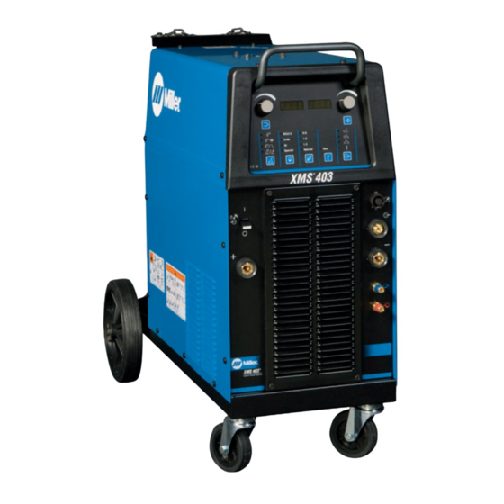
- Page 1 OM-244 243B 2009−10 Processes Multiprocess Welding Description Arc Welding Power Source XMS 403 (400 Volts) CE Visit our website at www.MillerWelds.com...
- Page 2 From Miller to You Thank you and congratulations on choosing Miller. Now you can get the job done and get it done right. We know you don’t have time to do it any other way. That’s why when Niels Miller first started building arc welders in 1929, he made sure his products offered long-lasting value and superior quality.
-
Page 3: Table Of Contents
TABLE OF CONTENTS SECTION 1 − SAFETY PRECAUTIONS - READ BEFORE USING ........1-1. -
Page 4: Declaration Of Conformity
Council Directive(s) and Standard(s). Product/Apparatus Identification: Product Stock Number XMS 403 015 029 083 Council Directives: • 2006/95/EC Low Voltage •... -
Page 5: Section 1 − Safety Precautions - Read Before Using
SECTION 1 − SAFETY PRECAUTIONS - READ BEFORE USING som _2009−08 Protect yourself and others from injury — read and follow these precautions. 1-1. Symbol Usage DANGER! − Indicates a hazardous situation which, if Indicates special instructions. not avoided, will result in death or serious injury. The possible hazards are shown in the adjoining symbols or explained in the text. - Page 6 D Remove stick electrode from holder or cut off welding wire at FUMES AND GASES can be hazardous. contact tip when not in use. D Wear oil-free protective garments such as leather gloves, heavy Welding produces fumes and gases. Breathing shirt, cuffless trousers, high shoes, and a cap.
-
Page 7: Additional Symbols For Installation, Operation, And Maintenance
1-3. Additional Symbols For Installation, Operation, And Maintenance FIRE OR EXPLOSION hazard. MOVING PARTS can injure. D Do not install or place unit on, over, or near D Keep away from moving parts such as fans. combustible surfaces. D Keep all doors, panels, covers, and guards D Do not install unit near flammables. -
Page 8: California Proposition 65 Warnings
1-4. California Proposition 65 Warnings For Gasoline Engines: Welding or cutting equipment produces fumes or gases which contain chemicals known to the State of California to Engine exhaust contains chemicals known to the State of cause birth defects and, in some cases, cancer. (California California to cause cancer, birth defects, or other reproduc- Health &... -
Page 9: Section 2 − Definitions
SECTION 2 − DEFINITIONS 2-1. Manufacturer’s Warning Label Definitions Warning! Watch Out! There are possible 2.1 Keep your head out of the fumes. Arc rays can burn eyes and injure hazards as shown by the symbols. skin. 2.2 Use forced ventilation or local exhaust to remove the fumes. - Page 10 Warning! Watch Out! There are possible hazards as shown by the symbols. Electric shock from wiring can kill. Disconnect input plug or power before working on machine. Hazardous voltage remains on input capacitors after power is turned off. Do not touch fully charged capacitors.
- Page 11 100 h. std. (B) 050024004 956 142 617 Warning! Watch Out! There are Wear approved safety glasses with Every 100 hours, check and clean filter possible hazards as shown by the side shields while working on the unit. and check condition of hoses. symbols.
-
Page 12: Symbols And Definitions
2-3. Symbols And Definitions Alternating Amperage Voltage Hertz Current (AC) Protective Earth Remote (Ground) Direct Current Line connection Three Phase Increase (DC) Lift-Arc Operation Gas Tungsten Arc Constant Voltage Constant Current (GTAW) Welding Three Phase Static Recycle or dispose Frequency Con- Gas Metal Arc Shielded Metal Arc of used coolant in... -
Page 13: Section 3 − Installation
SECTION 3 − INSTALLATION 3-1. Important Information Regarding CE Products (Sold Within The EU) This equipment shall not be used by the general public as the EMF limits for the general public might be exceeded during welding. This equipment is built in accordance with EN 60974−1 and is intended to be used only in an occupational environment (where the general public access is prohibited or regulated in such a way as to be similar to occupational use) by an expert or an instructed person. -
Page 14: Volt-Ampere Curves
3-5. Volt-Ampere Curves Volt-ampere curves show minimum and maximum voltage and amper- age output capabilities of unit. Curves of other settings fall be- tween curves shown. A. CC Mode B. CV Mode ARC CONTROL va_curve1 4/95 − SA-178 652 / SA-178 653 3-6. -
Page 15: Dimensions And Weight
3-7. Dimensions And Weight Dimensions 1010 mm (39.7 in.) Weight 90 kg (198 lb) 860 mm (33.8 in.) 490 mm (19.3 in.) Ref. 956142645-3-5 3-8. Selecting a Location Handle Do not use handle to lift unit. Line Disconnect Device Locate unit near correct input power supply. -
Page 16: Weld Output Terminals And Selecting Cable Sizes
3-9. Weld Output Terminals And Selecting Cable Sizes NOTICE − The Total Cable Length in Weld Circuit (see table below) is the combined length of both weld cables. For example, if the power source is 100 ft (30 m) from the workpiece, the total cable length in the weld circuit is 200 ft (2 cables x 100 ft). Use the 200 ft (60 m) column to determine cable size. -
Page 17: Remote 7 Receptacle Information (Tig And Stick Only)
7-Pin Remote Receptacle TYPE 0V/10V digital signal This remote receptacle cannot be used with a standard Miller remote control. A customer supplied remote control is required to use the remote receptacle. Some signals can be enabled when TIG or Stick welding. Contact Factory Authorized Service Agent for confirmation. -
Page 18: Filling Coolant Tank
Coolant *HF: High Frequency Current ° ° **MILLER coolants protect to -37 F (-38 C) and resist algae growth. NOTICE − Use of any coolant other than those listed in the table voids the warranty on any parts that come in contact with the coolant (pump, radiator, etc.). -
Page 19: Connecting 3-Phase Input Power
3-14. Connecting 3-Phase Input Power Installation must meet all National and Local Codes − have only quali- fied persons make this installation. Disconnect and lockout/tagout in- put power before connecting input conductors from unit. Always connect green or green/ yellow conductor to supply grounding terminal first, and nev- er to a line terminal. -
Page 20: Section 4 − Operation
SECTION 4 − OPERATION 4-1. Front Panel Controls Ref. 956142645-5-5 ON/OFF Switch (I/O) Coolant output to torch. 15 P2 (Setup Push Button) Use switch to turn unit On/Off. Handle Allows selecting setup or advanced pro- gramming menus. Control Panel The power source cooling fan is 16 P3 (Process Push Button) 10 D1 (Display 1) thermally controlled running only as re-... -
Page 21: Switching On The Unit And Recalling Factory Parameters
Power Switch Use power switch to turn unit On. When XMS 403 appears on D1 and D2, press P3 and P8 simultaneously. When MEMO CLEAR appears on D1 and D2, release P3 and P7. -
Page 22: Welding Power Source Setup Menu
P1 - Welding Parameter Setup But- ton. P2 - Power Source Setup Button. Press and hold P1 and P2. XMS 403 appears on D1 and D2 fol- lowed by UNIT - IPM. Wire feed speed is displayed as (IPM) inches per minute. -
Page 23: Remote Receptacle (Rcty)
4-4. Remote Receptacle (RCTY) 7 Pin Remote Receptacle 4-5. Welding Process Selection Ref. 956142645-5-5 L1 LED L2 Synergic MIG welding (non-pulsed). D1 value is welding voltage, default is 20 V (range is −10 V to 50 V). D1 value is welding voltage, default is 16.5 L2 LED V (range is −10 V to 50 V). -
Page 24: Wire Type Selection In Synergic Mig Or Synergic Pulsed Mig Welding
4-6. Wire Type Selection in Synergic MIG or Synergic Pulsed MIG Welding Ref. 956142645-5-5 L5 LED is no program for the process, material, SG2/3 allows selecting SG2 or SG3. wire diameter, and shielding gas com- L6 LED CrNi allows selecting 308L, 309L, or 316L. bination. -
Page 25: Gas Selection In Synergic Mig Or Synergic Pulsed Mig Welding
4-8. Gas Selection in Synergic MIG or Synergic Pulsed MIG Welding Ref. 956142645-5-5 L13 LED E2 encoder to select desired gas type. After PROG or alternate selection will not be a brief moment the the displays will return to possible when either process, material, P6 Push Button the main parameters. -
Page 26: Welding Parameter Setup Menu (Double Pulsed-Mig/L-Tig And Stick)
4-10. Welding Parameter Setup Menu (Double Pulsed-MIG/L-TIG And Stick) Press P2 to enter SET UP menu. SET UP will appear on D1 and D2 momentarily changing to the se- lected process parameter values. Setup permits the viewing and changing of default parameters for each process mode. -
Page 27: Selecting Manual Mig Welding
4-12. Selecting Manual MIG Welding Ref. 956142645-5-5 Set Manual MIG welding process using P3 During Setting : During MIG Welding: push button. D1 value is Measured Welding Voltage in D1 value is default voltage setting of 18.5 V Volts. (range is 10.0 V to 50.0 V). In Manual MIG mode, the operator may D2 value is Measured Welding Amperage need to adjust main welding parameters for... -
Page 28: Selecting Synergic Mig Welding
4-13. Selecting Synergic MIG Welding Ref. 956142645-5-5 Set Synergic MIG welding process using defined by wire type, wire diameter and gas Select wire type using P4 push button. P3 push button. type selection). Select wire diameter using P5 push button. D2 value is the default current setting In Synergic MIG mode, the operator may Select gas using P6 push button. -
Page 29: Selecting Synergic Pulsed Mig Welding
4-14. Selecting Synergic Pulsed MIG Welding Ref. 956142645-5-5 Set Synergic Pulsed MIG welding process During Synergic MIG Welding: Incorrect settings in Synergic Double using P3 push button. Pulsed Welding process can result in a D1 value is Measured Welding Voltage in Volts. -
Page 30: Preparing Unit For Tig Welding
4-15. Preparing Unit For TIG Welding Ref. 956142645-5-5 To prepare unit for TIG welding, proceed as Setting Slope-Up Time If D1 does not display TIG proceed as follows: follows: Press P2 to enter SET UP menu. Follow safety precautions according to Press P2 setup button. -
Page 31: Tig Lift-Arc Welding
4-16. TIG Lift-Arc Welding Lift-Arc Start When process selector LED 4 is il- luminated in TIG mode Lift-Arc TIG is enabled. TIG Electrode Workpiece Touch tungsten electrode to work- piece at weld start point, enable out- put and shielding gas with torch trig- ger, foot control, or hand control. -
Page 32: Section 5 − Maintenance & Troubleshooting
Repair Or Replace Cracked Cables And Cords Clean Tighten Weld Connections 6 Months Blow Out Inside Replace Cracked Hoses Change Blow Out Heat Coolant (If Exchanger Fins Using Water) 12 Months Change Coolant (If Using MILLER Coolant) OM-244 243 Page 28... -
Page 33: Help Displays
5-2. Help Displays Help 4 Help 8 All directions are in reference to the front of the unit. All circuitry referred to is Indicates a malfunction in the thermal protec- Indicates a malfunction in the secondary located inside the unit. tion circuitry on right side of unit. -
Page 34: Section 6 − Electrical Diagram
SECTION 6 − ELECTRICAL DIAGRAM Figure 6-1. Circuit Diagram For XMS 403 OM-244 243 Page 30... - Page 35 956142623 OM-244 243 Page 31...
-
Page 36: Section 7 − Parts List
SECTION 7 − PARTS LIST Hardware is common and not available unless listed. 956142645A-1-5 Figure 7-1. Unit Outer Assembly OM-244 243 Page 32... - Page 37 Item Dia. Part Mkgs. Description Quantity Figure 7-1. Unit Outer Assembly ....+V17031284 . . . Wrapper ..........
- Page 38 Hardware is common and not available unless listed. 956142645A-2-5 Figure 7-2. Unit Main Assembly OM-244 243 Page 34...
- Page 39 Item Dia. Part Mkgs. Description Quantity Figure 7-2. Unit Main Assembly ..... . 316005010 . . . LEM, Support ..........
- Page 40 Item Dia. Part Mkgs. Description Quantity Figure 7-2. Unit Main Assembly (Continued) ....V58021080 . . . Transformer, 400VAC ........
- Page 41 Notes MATERIAL THICKNESS GAUGE...
- Page 42 Notes SOCKET/WRENCH SELECTION TABLE SOCKET/WRENCH SELECTION TABLE (U.S. STANDARD) (METRIC) Specifications Socket or Wrench Size Specifications Socket or Wrench Size U.S. Bolt Decimal Bolt Bolt Decimal Bolt Diameter Equivalent Diameter Equivalent 1/4 in .250 in 3/8 in 7/16 in 6 mm .2362 in 10 mm 10 mm...
- Page 43 Effective January 1, 2009 This limited warranty supersedes all previous Miller warranties and is exclusive with no other guarantees or warranties expressed or implied. LIMITED WARRANTY − Subject to the terms and conditions 90 Days — Parts below, ITW Welding Products Italy warrants to its original retail...
- Page 44 File a claim for loss or damage during Phone: 39 (0) 2982901 Fax: 39 (0) 298290-203 shipment. email: miller@itw−welding.it For assistance in filing or settling claims, contact your distributor and/or equipment manufacturer’s Transportation Department. © ORIGINAL INSTRUCTIONS − PRINTED IN USA 2009 Miller Electric Mfg. Co. 2009−01...
Need help?
Do you have a question about the XMS 403 and is the answer not in the manual?
Questions and answers