Sign In
Upload
Download
Table of Contents
Contents
Add to my manuals
Delete from my manuals
Share
URL of this page:
HTML Link:
Bookmark this page
Add
Manual will be automatically added to "My Manuals"
Print this page
×
Bookmark added
×
Added to my manuals
Manuals
Brands
Biddle Manuals
Fan
DECO 50
Manual
Biddle DECO 50 Manual
Fan coil unit
Hide thumbs
1
2
Table Of Contents
3
4
5
6
7
8
9
10
11
12
13
14
15
16
17
18
19
20
21
22
23
24
25
26
27
28
29
30
31
32
33
34
35
36
page
of
36
Go
/
36
Contents
Table of Contents
Bookmarks
Table of Contents
Table of Contents
Introduction
About this Manual
How to Use this Manual
Marginal Symbols
Pictograms on the Device and in the Guide
Related Documentation
About the Unit
Uses
Working
Available Models, and Type References
Type Plate
Available Components and Accessories
Safety Instructions
Operation
Installation, Maintenance and Service
Installation
Safety Instructions
Delivery Check
General Working Method
Mounting Wall Duct (Accessory)
Details
Mounting
Mounting Roof Duct (Accessory)
Details
Mounting
Mounting Attenuated Inlet Section (Accessory)
Details
Mounting
Removing Side Panels from Unit
Mounting Unit
Determining Mounting Position and Method
General
Mounting Wall Model
Mounting Wall Model to Attenuated Inlet Section
Mounting Ceiling Model
Connecting Unit (Models with Water Heating And/Or Cooling)
Details
Frost Protection
Connecting Water Pipes
Connecting Condensate Drain
Electrical Connection
Connecting Unit (Electrically Heated Models)
Installing Controller
Replacing Side Panels Onto Unit
Mounting Duct Sections and Grilles (Accessories)
Switching on and Checking Operation
Operation
Introduction
Regulating Discharge Direction
Maintenance
Replacing or Cleaning the Filter
Introduction
Replacing Filter
Cleaning the Unit
Exterior
Inlet Grille
Discharge Grille
Periodical Maintenance
Service
Safety Instructions
Opening Unit
Removing Side Panels
Removing Front Panel
Opening the Electronics Compartment
Replacing Fuses
EC Declaration of Agreement
Declaration of Conformity
Advertisement
Quick Links
1
Electrical Connection
Download this manual
Manual
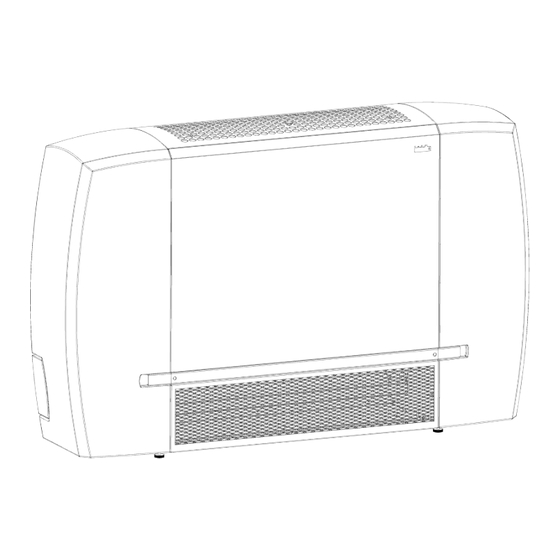
Fan Coil Unit
Model DECO
R
Version of guide: 4.0
a
Table of
Contents
Previous
Page
Next
Page
1
2
3
4
5
Advertisement
Table of Contents
Need help?
Do you have a question about the DECO 50 and is the answer not in the manual?
Ask a question
Questions and answers
Related Manuals for Biddle DECO 50
Fan Biddle DECO 150 Manual
Fan coil unit (36 pages)
Fan Biddle DECO 75 Manual
Fan coil unit (36 pages)
Fan Biddle DECO 100 Manual
Fan coil unit (36 pages)
Fan Biddle Innovair Size 3 Installation, Operation & Maintenance Instructions Manual
Intelligent fan convectors (27 pages)
Fan Biddle PROAIR Series Installation, Operating And Maintenance Instructions For The Installer And The User
Fan coil unit (16 pages)
Fan Biddle PS Series Manual
Modular fan coil unit (20 pages)
This manual is also suitable for:
Deco 150
Deco 75
Deco 100
Deco 125
Table of Contents
Print
Rename the bookmark
Delete bookmark?
Delete from my manuals?
Login
Sign In
OR
Sign in with Facebook
Sign in with Google
Upload manual
Upload from disk
Upload from URL


Need help?
Do you have a question about the DECO 50 and is the answer not in the manual?
Questions and answers