
Related Manuals for Biddle PROAIR Series


Summary of Contents for Biddle PROAIR Series
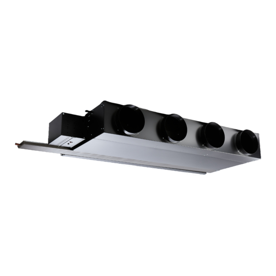
- Page 1 Issue: 1.6 PROAIR SERIES PROAIR235 & PROAIR270 Fan Coil Unit INSTALLATION, OPERATING AND MAINTENANCE INSTRUCTIONS Original Instructions...
- Page 2 Copyright and trademarks All the information and drawings in this manual are the property of Biddle and may not be used (other than for the actual operation of the device), photocopied, duplicated, translated and/or be brought to the attention of third parties without Biddle’s prior written permission.
-
Page 3: Table Of Contents
Installing Inlet Extension (Optional) ....................... 7 Connecting Ductwork ..........................7 Connecting the Electrical Supply ......................8 Connecting the Controls Cabling ......................9 Biddle Specified Controls ........................9 Commissioning and Setting to Work ....................... 10 Initial Startup ............................11 Service and Maintenance ........................11 Warranty and Repairs .......................... -
Page 4: Introduction
Introduction This Installation, Operation and Maintenance manual relates to the PROAIR235 & PROAIR270 Horizontal Fan Coil Units (FCU) designed and manufactured by Biddle to provide cooling and heating to internal spaces. The information contained in this document provides guidance on how this product is installed, operated and maintained. -
Page 5: Storage
given supervision or instruction concerning use of the appliance in a safe way and understand the hazards involved. Children shall not play with the appliance. Storage The product must be stored in a dark, dry, frost free and well ventilated place out of the reach of children. -
Page 6: Installing The Fan Coil Unit
Valves – The unit is typically supplied with either project specific (free issued) valves, or Biddle’s standard 4 port offer. The customer is to ensure that isolation valves are placed suitably close to the unit to allow for disconnection during future servicing and maintenance. -
Page 7: Installing Inlet Extension (Optional)
Condensate pumps can be fitted to the unit to provide an initial lift to a gravity drain system. The pump contains an alarm function that can signal either pump failure, or that excessive condensation is being produced. When the unit is purchased with Biddle’s standard controls, Page 7... -
Page 8: Connecting The Electrical Supply
this alarm will be interlocked with the cooling actuator such that cooling will be disabled until the condensate is removed. Connecting hot and cold water services The unit incorporates a water to air heat exchanger with provision to connect to both cooling and hot water services. -
Page 9: Connecting The Controls Cabling
• Biddle specified controls – a digital controller is supplied and fitted to control the temperature and fan speeds with optional wall controllers. The remainder of this section is related wholly to the Biddle Specified Controls. -
Page 10: Commissioning And Setting To Work
The TUC03 will allow multiple similar products to be connected together to ensure they all heat/cool collectively. Where multiple units are used in the same space, Biddle recommend that this function is enabled to avoid each unit competing against each other causing substantial increase in running costs. -
Page 11: Initial Startup
Warranty and Repairs If any problems are encountered, please contact your installer or supplier. Failing this please contact the Biddle warranty department. All units are covered by a one year warranty on parts and labour, followed by two addition years parts only. -
Page 12: Fan Replacement
increased wear on the fan and increased the noise levels. The filter is removed by undoing the two retaining screws situated beneath the filter that allows a hinged section to be pulled down giving access to the filter. The filter is of non-woven nylon manufacture and should be regularly cleaned from the dirty side with a vacuum cleaner or can be partially cleaned by gentle tapping. -
Page 13: Condensate Drain Trays
Condensate Drain Trays Drain trays should be periodically checked to ensure they are clean, unobstructed and free draining. Should they become excessively dirty or blocked, they should be removed and cleaned. To remove the drain tray you first have to remove the fan access panel as previously described. -
Page 14: Maintenance Schedule
Visually inspect the wiring, terminals and all other components for any sign of discolouration, arcing or charring. Check for blown fuses. If a fuse is blown check the circuits and components it protects thoroughly before re energising. Any blown fuse must be replaced with an equivalent fuse of the same specification, size and rating. -
Page 15: Spare Parts
Spare Parts PROAIR235 - Unit Size Item Filters Qty Fitted: Stock Code: 95200010 95200011 95200011 95200012 95200012 95200013 95200014 95200014 95200015 95200015 Stock Code: 95200016 95200017 95200017 95200018 95200018 95200019 95200020 95200020 95200021 95200021 Qty Fitted: Fans Stock Code: 95200034 95200034 95200034 95200034... - Page 16 PROAIR270 - Unit Size Item Filters Qty Fitted: Stock Code: 95200022 95200023 95200023 95200024 95200024 95200025 95200026 95200026 95200027 95200027 Stock Code: 95200028 95200029 95200029 95200030 95200030 95200031 95200032 95200032 95200033 95200033 Qty Fitted: Fans Stock Code: 95200035 95200035 95200035 95200035 95200035 95200035...
Need help?
Do you have a question about the PROAIR Series and is the answer not in the manual?
Questions and answers