Table of Contents
Advertisement
Quick Links
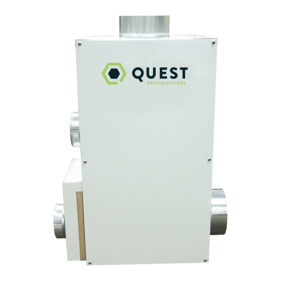
Quest Dry
Quest Dry 132D
Installation, Operation and Maintenance Instructions
Installation, Operation and Maintenance Instructions
– Read and Save These Instructions –
– Read and Save These Instructions –
This manual is provided to acquaint you with the
dehumidifier so that installation, operation and
maintenance can proceed successfully. Ultimate
satisfaction depends on the quality of installation
and a thorough understanding of this equipment.
The dehumidifier is built around tested engineering
principles and has passed a thorough inspection for
quality of workmanship and function.
Quest Dry 132D:
• Low dewpoint operation
• 132 Pints/Day @ AHAM
• Wide operating range
• 24 Amps total power consumption
• Factory installed 115VAC power cords
(2 required @ 15 Amps each)
• Simple ON/OFF operation with optional
low voltage control for remote/dehumidistat operation
• Vertical or horizontal operation
• Multiple ducting options
Specifications subject to change without notice.
Water Removal Rates (Pints/Day)
65 Pints
180 Pints
150 Pints
132 Pints
130 Pints
120 Pints
120 Pints
115 Pints
125 Pints
100 Pints
30 Pints
4201 Lien Rd
Madison, WI 53704
www.QuestHydro.com
1
100°F, 20%
90° F, 90%
80° F, 80%
80° F, 60% (AHAM)
70° F, 80%
70° F, 60%
60° F, 80%
60° F, 60%
50° F, 80%
50° F, 60%
10° F, 80%
Phone 608-237-8400
Toll-Free 1-877-420-1330
info@QuestHydro.com
TS-1030
10/17 Rev. A
Advertisement
Table of Contents

Related Manuals for Quest Engineering Dry 132D


Summary of Contents for Quest Engineering Dry 132D
- Page 1 Quest Dry Quest Dry 132D Installation, Operation and Maintenance Instructions Installation, Operation and Maintenance Instructions – Read and Save These Instructions – – Read and Save These Instructions – This manual is provided to acquaint you with the dehumidifier so that installation, operation and maintenance can proceed successfully.
-
Page 2: Table Of Contents
Isolated Reactiation Duct ........5 c. Outside Drying Space .........5 3. Operation ................5 3.1 How the Quest DRY 155 Works ......5 3.2 Controlling the Quest Dry 132D ......6 4. Maintenance ..............6 4.1 Air Filters ..............6 4.2 Blower Motors and Rotor Drive Motor ....7 4.3 Desiccant Rotor Cassette Assembly .....7... -
Page 3: Safety Precautions
Proper adherence to these instructions is essential to obtain maximum benefit from your Quest Dry 132D. READ AND SAVE THESE INSTRUCTIONS The Quest Dry 132D can be installed in a variety of locations to meet the owner’s needs as listed below. In all cases, keep the following cautions in mind: •... -
Page 4: Specifications
Quest Dry 132D Installation, Operation and Maintenance Instructions 1. Specifications Part Number: 4037900 Power: 2 Circuits; 12Amps, 115VAC each 24 Amps total power consumption Kilowatts: 2.8 (66 KWh/Day) Capacity per Day: 132 Pints (80°F 60%RH) Blower: 385 CFM Process Ariflow @ 0” ESP 75 CFM Reactivation Airflow @ 0”ESP... -
Page 5: Installation
2. Installation Moist Air 2.1 Electrical Requirements The Quest Dry 132D draws a total of 24 Amps at 115VAC. For convenience, this can be supplied by two standard 15 Amp outlets on separate circuits (cords Conditioned Space provided). The Quest Dry 132D also allows for the connection of low voltage remote dehumidistat controls (sold separately). -
Page 6: Controlling The Quest Dry 132D
3.2 (a) IMPORTANT: Line-voltage controls that interrupt power to the unit may not be used with the Quest Dry 132D. The unit uses an internal thermal cutout that may be reset inadvertently if power to the unit is disconnected 4. -
Page 7: Blower Motors And Rotor Drive Motor
5.2 Technical Description a. Main Components The Quest Dry 132D produces airflow using two permanent split capacitor (PSC) blower motors. A shaded-pole gear motor rotates the desiccant rotor via a pulley and belt. Heat for reactivation is generated by a two-stage nichrome heating element powered by two separate branch circuits. -
Page 8: Control Circuit
Quest DRY 132D Installation, Operation and Maintenance Instructions b. Control Circuit The blowers, rotor motor, and heating elements are operated by a line- and low-voltage control circuit. One branch circuit (Circuit 1) delivers power to the process blower, control transformer, and a 1270W heating element through one line-voltage relay (Relay 1) and a control relay. -
Page 9: Troubleshooting
Quest DRY 132D Installation, Operation and Maintenance Instructions 5.4 Troubleshooting Each cord must be plugged into a separate branch circuit. Plugging both cords into the same circuit will likely cause the branch circuit protector (e.g. fuse or breaker) to trip. -
Page 10: Wiring Diagram
Quest DRY 132D Installation, Operation and Maintenance Instructions 6. Wiring diagram ctions CORD 1 CORD 2 ROTOR MOTOR TERMINAL BLOCK TERMINAL BLOCK MAIN POWER SWITCH ORG 31 BLK 28 YEL 20 YEL 19 EXTERNAL CONTROL BREAKER GRN 24 WHT 23... -
Page 11: Service Parts List
Quest Dry 132D Installation, Operation and Maintenance Instructions Quest DRY 115 Installation, Operation and Maintenance Instructions 7. Service Parts List 6. Service Parts List Item Part No. Description Item Part No. Description 4025076 FAN, MOTORIZED IMPELLER, PROCESS AIR 4025076 FAN, MOTORIZED IMPELLER, PROCESS AIR... -
Page 12: Warranty
(but all warranty periods will be extended by the period of time, if any, that the Quest Dry 132D Dehumidifier is out of service while awaiting covered warranty service).
Need help?
Do you have a question about the Dry 132D and is the answer not in the manual?
Questions and answers