Advertisement
Advertisement

Related Manuals for Maximum 055-6766-2


Summary of Contents for Maximum 055-6766-2
-
Page 2: Table Of Contents
TABLE OF CONTENTS Quick start guide Specifications Safety guidelines Know your table saw Assembly Operation Maintenance Troubleshooting Exploded view Parts list Warranty NOTE: If any parts are missing or damaged, or if you have any questions, please call our toll-free helpline at 1-888-670-6682. SAVE THESE INSTRUCTIONS This manual contains important safety and operating instructions. -
Page 3: Specifications
055-6766-2 | contact us 1-888-670-6682 model no. 055-6766-2 | contact us 1-888-670-6682 SPECIFICATIONS This portable table saw is designed to cut wood and wood composition products only. The tool can be used for straight-line cutting operations such as crosscutting, ripping, mitring 0-45°... -
Page 4: Safety Guidelines
055-6766-2 | contact us 1-888-670-6682 model no. 055-6766-2 | contact us 1-888-670-6682 SAFETY GUIDELINES • Store the operating instructions so that they are always available to the user of the tool when it is being operated. This manual contains information that relates to PROTECTING PERSONAL SAFETY and •... - Page 5 • Use the push rod to pass the workpiece safely into the saw blade. Do not come too close to the saw blade. WARNING! • Make sure that the thickness of the material to be cut is less than the maximum possible • The use of other insertion tools and accessories can cutting depth.
- Page 6 055-6766-2 | contact us 1-888-670-6682 model no. 055-6766-2 | contact us 1-888-670-6682 GROUNDING INSTRUCTIONS: USE DUST MASK: • Make sure the extension cord is in good condition. When using an extension cord, be Some dust created by sawing contains chemicals that are known to cause sure to use one that is heavy enough to carry the current that your product will draw.
- Page 7 055-6766-2 | contact us 1-888-670-6682 model no. 055-6766-2 | contact us 1-888-670-6682 Recommended size for extension cords AMPERAGE RATING OF THE TOOL TOTAL LENGTH OF THE EXTENSION CORD 150' (45.7 m) (120 V CIRCUIT ONLY) 25' (7.6 m) 50' (15.2 m)
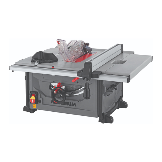
- Page 8 Description Description Blade guard Anti-kickback pawls storage For maximum performance, it is recommended that you use the 40-tooth, 10" (25.4 cm) carbide-tipped combination blade provided with your saw. The blade is raised and Rip fence Dust extraction port lowered with the height/bevel adjusting handwheel. Bevel angles are locked with the...
-
Page 9: Assembly
055-6766-2 | contact us 1-888-670-6682 model no. 055-6766-2 | contact us 1-888-670-6682 RIP FENCE for the basic cuts: cross cuts, mitre cuts, bevel cuts and compound cuts. The rip fence is a sturdy metal fence that can be locked to the work table to guide the The rip fence is used to position work for lengthwise cuts. - Page 10 055-6766-2 | contact us 1-888-670-6682 model no. 055-6766-2 | contact us 1-888-670-6682 PACKAGE CONTENTS • Inspect the workpiece for knots or nails before beginning a cut. Knock out any loose knots with a hammer. Never saw into a loose knot or nail.
- Page 11 055-6766-2 | contact us 1-888-670-6682 model no. 055-6766-2 | contact us 1-888-670-6682 UNPACKING Description Qty Illustration Do not use this product if any parts of the package contents are already assembled to your product when you unpack it. Package contents are not assembled to the product by Blade wrenches the manufacturer and require customer installation.
- Page 12 055-6766-2 | contact us 1-888-670-6682 model no. 055-6766-2 | contact us 1-888-670-6682 MOUNTING HOLES (Fig. 1) TO USE THE OUTFEED SUPPORT (Fig. 4) The table saw must be mounted to a firm, supporting, The outfeed support slides to give the operator waist-high surface such as a workbench or leg stand.
- Page 13 055-6766-2 | contact us 1-888-670-6682 model no. 055-6766-2 | contact us 1-888-670-6682 HEIGHT/BEVEL ADJUSTING HANDWHEEL ADJUSTING THE RIVING KNIFE (Fig. 11-13) (Fig. 8) This saw is shipped with the riving knife placed in “down” position. • Turn the height adjusting knob (1) clockwise to •...
- Page 14 • Set the blade angle to 0°. Make sure that blade guard body is parallel to the • Raise the saw blade to maximum height by turning table. If it is not, adjust the set screw (15) as height adjustment knob clockwise.
- Page 15 055-6766-2 | contact us 1-888-670-6682 model no. 055-6766-2 | contact us 1-888-670-6682 CHECK AND ALIGN THE RIVING KNIFE AND TO CHECK SAW BLADE INSTALLATION (Fig. 21) SAW BLADE (Fig. 19-20) The saw is shipped with the blade installed. Prior to...
- Page 16 055-6766-2 | contact us 1-888-670-6682 model no. 055-6766-2 | contact us 1-888-670-6682 TO REPLACE THE SAW BLADE (Fig. 22) CHANGING THE BLADE DEPTH (Fig. 23) When you need to replace the saw blade, please The saw blade depth should be set so that the outer...
- Page 17 CHECKING THE ALIGNMENT OF THE RIP blade guard assembly. FENCE TO THE BLADE (Fig. 29) • Raise the blade to the maximum height by turning the height-adjusting knob clockwise. • Unplug the saw. • Using a framing square (1), set the blade to exactly •...
- Page 18 055-6766-2 | contact us 1-888-670-6682 model no. 055-6766-2 | contact us 1-888-670-6682 USING THE RIP FENCE (Fig. 30) TO ADJUST MITRE GAUGE (Fig. 32) 90° 45° • Unplug the saw. Loosen the locking handle (1). Raise the orientation •...
- Page 19 055-6766-2 | contact us 1-888-670-6682 model no. 055-6766-2 | contact us 1-888-670-6682 CONNECT TO A DUST COLLECTION SYSTEM BASIC OPERATION OF THE TABLE SAW (Fig. 34) The three-prong plug must be plugged into a matching outlet that is properly installed and The dust extraction port (1) with 2.5"...
- Page 20 055-6766-2 | contact us 1-888-670-6682 model no. 055-6766-2 | contact us 1-888-670-6682 MAKING CUTS TO LOCK YOUR SAW: • Press the switch down. Before using the table saw, polish the table with an automotive wax in order to keep it •...
- Page 21 055-6766-2 | contact us 1-888-670-6682 model no. 055-6766-2 | contact us 1-888-670-6682 PUSH STICK (Fig. 37) RIPPING (Fig. 38) • Remove the mitre gauge, and secure the rip fence Push sticks are devices used for safely pushing a workpiece through the blade instead of using your hands.
- Page 22 055-6766-2 | contact us 1-888-670-6682 model no. 055-6766-2 | contact us 1-888-670-6682 BEVEL RIPPING CROSSCUTTING (Fig. 40) • Remove the rip fence, and place the mitre gauge in This operation is the same as ripping, except that the bevel angle is set to an angle other than 0°.
- Page 23 055-6766-2 | contact us 1-888-670-6682 model no. 055-6766-2 | contact us 1-888-670-6682 BEVEL CROSSCUTTING 0-45° BLADE BEVEL MITRING 0-45° MITRE ANGLE (Fig. 43) AND 90° MITRE ANGLE (Fig. 41) This sawing operation is the same as crosscutting, except that the mitre gauge is locked at an angle This cutting operation is the same as crosscutting, other than 90°.
- Page 24 055-6766-2 | contact us 1-888-670-6682 model no. 055-6766-2 | contact us 1-888-670-6682 GENERAL MAINTENANCE BLADE RAISING AND TILTING MECHANISM (Fig. 46) Avoid using slovents when cleaning plastic parts. Most plastics are susceptible to damage from various types of commercial solvents and may be damaged by their use. Use clean Check the blade raising and tilting mechanism for cloths to remove dirt, dust, oil, grease, etc.
-
Page 25: Troubleshooting
055-6766-2 | contact us 1-888-670-6682 model no. 055-6766-2 | contact us 1-888-670-6682 TROUBLESHOOTING PROBLEM Possible Causes Solution • Rip fence out of adjustment. • Align rip fence with mitre Material kicked back PROBLEM Possible Causes Solution from blade. - Page 26 055-6766-2 | contact us 1-888-670-6682 model no. 055-6766-2 | contact us 1-888-670-6682...
- Page 27 055-6766-2 | contact us 1-888-670-6682 model no. 055-6766-2 | contact us 1-888-670-6682 142 141...
-
Page 28: Parts List
055-6766-2 | contact us 1-888-670-6682 model no. 055-6766-2 | contact us 1-888-670-6682 PARTS LIST Description Description Guard spring Screw M6 x 16 Description Description Guard screw M5 x 10 Hinge Mitre gauge Handle Handle Pin cap Protection spring Large gasket Ø6... - Page 29 055-6766-2 | contact us 1-888-670-6682 model no. 055-6766-2 | contact us 1-888-670-6682 Description Description Description Description Bolt M4.2 x 14 Frame groupware Bolt ST4.2 x 18 Pole Stop block Locking nut M5 Switch Limitation plate (a) Insert (b) Bolt ST4.2 x 10...
- Page 30 Neither the retailer, Maximum Canada, nor the manufacturer shall be liable for any other (1) The carrying case, which is only for a period of 1-year from the date of original expense, loss or damage, including, without limitation, any indirect, incidental, retail purchase against defects in workmanship and materials.
-
Page 31: Warranty
In addition to the 5-Year Limited Warranty, this MAXIMUM product is covered by our: 1-Year Repair Warranty Maximum Canada will maintain this product and replace critical parts which have worn beyond reasonable use through normal use of such product, any time during the first...
Need help?
Do you have a question about the 055-6766-2 and is the answer not in the manual?
Questions and answers