Table of Contents
Advertisement
Quick Links
Advertisement
Table of Contents
Troubleshooting

Related Manuals for NEC ShieldPRO N22A


Summary of Contents for NEC ShieldPRO N22A
- Page 1 NEC Factory Computer FC-NOTE Series N22A User’s Manual...
-
Page 2: Introduction
All other product, brand, or trade names used in this publication are the trademarks or registered trademarks of their respective trademark owners. © NEC Corporation 2008 No part of this manual may be reproduced in any form without the prior written permission of NEC Corporation. -
Page 3: About This Document
About this document This is a guide for correctly setting up and using the FC-N22. This document comes in the following structure. Manual structure Be sure to read the following before using the computer. For safe use Describes information required to safely Read me first use this computer ... -
Page 4: For Safe Use
For safe use The following includes information necessary for proper and safe operation of the product. Before using this product, read this manual carefully and keep cautions. Keep this manual at hand to see whenever it is necessary. The following symbols are used in this manual so that the user can avoid personal injury or damage to the properties. - Page 5 Warning on using the main unit WARNING If this device emits smoke or an odd smell, or the main unit is too hot to touch, turn the power off immediately then remove the power cable plug from the AC outlet. If the battery is connected, remove it after checking for safety.
- Page 6 Warning on connection of power supply WARNING The AC adapter and AC cord are designed on the assumption that it is connected to this product. The AC adapter may be damaged if it is connected to a device other than this product.
- Page 7 The drip-proof and dust-proof performance conforming to IP54 are not applied to the AC adapter and AC cord. Follow instructions described below when handling them to prevent fume, fire, and/or electric shock to occur. Do not drop or give impact to the battery. ...
- Page 8 When installing or removing a peripheral device, be sure remove the cigar lighter plug of the power cable from the cigar lighter socket, to avoid electric shock. Do not insert or remove the cigar lighter plug of the power cable to or from the cigar lighter socket with a wet hand, to avoid electric shock.
- Page 9 Disassembling or modifying the battery may cause an explosion or liquid leakage. Use of a battery other than one specified by NEC, or a disassembled or modified battery (except those repaired by NEC) are not subject to guarantee for quality, performance, or safety.
- Page 10 Warning on use of wireless functions WARNING Any users with implantable cardiac pacemakers should make this product apart from the pacemakers by 30 cm or longer. The pacemakers may be influenced by radio waves radiated from this product. ...
- Page 11 Other warnings WARNING Keep the battery away from the reach of children, especially babies and toddlers. Battery contains harmful materials. Swallowing or licking them can be very dangerous. If swallowed, contact a physician immediately. Always use the specified battery with its polarities correctly orientated.
- Page 12 Caution on use of the main unit CAUTION Do not use the main unit on lap for a long time The bottom surface of this product may heat during operation, causing a low-temperature burn. A low-temperature burn is a burn symptomized by redness or spotting of the skin when a specific portion has been in contact with a heating object for a long time.
- Page 13 Cautions on use of peripheral devices CAUTION Be careful when using the device with the tray of the external CD/DVD drive ejected. Bumping or hitting hand or leg to the CD/DVD drive tray may cause injury or damage the device. ...
- Page 14 Other cautions CAUTION Use of wireless communication devices of this product may badly affect hearing aids, such as by producing noise. Check for correct operation before using, to avoid hearing damage. Be careful not to adjust the volume too loudly when using headphones or headphone/microphone set.
- Page 15 (4) NEC assumes no liability arising from the use of this product, nor any liability for incidental or consequential damages arising from the use of this manual regardless of Item (3).
- Page 16 This product is a radio equipment that satisfies “Station of the small electric power data communications system” defined in Article 6, Paragraph 4 of the radio law ministerial ordinance in Japan. It also satisfies “Local telecommunication terminal equipment using the radio wave”...
- Page 17 5.47 – 5.725 GHz is current not allowed in Czech Republic and France. R&TTE Directive We, the manufacturer (NEC Corporation) hereby declare that this equipment (N22A), model XXX is in compliance with the essential requirements and other relevant provisions of Directive 1999/5/EC.
- Page 18 It is strongly recommended that the Hard Disk Erase feature in BIOS SETUP menu or the software or service (both available at stores) for data erasure should be used in order to avoid the trouble explained above. NEC shall not assume any liability for such data leakage caused by your failure to take necessary measures.
- Page 19 To protect valuable resources, do not dispose batteries becoming unnecessary, but bring them to any of the following carry-on centers. * For details of the carry-on centers, see the NEC environmental web page below: URL:http://www.nec.co.jp/eco/ja/products/3r/indes_denchi.html (As of May 2008) ...
- Page 20 (5) Continuous operation of N22A for long period If N22A is operated continuously for a long period, deterioration of life parts in N22A may be accelerated. Therefore, NEC may charge the repair of N22A defected due to continuous operation for a long period within the warranty period.
-
Page 21: For Health
When using the LCD in the high brightness condition for a long time, it is recommended to set the backlight to automatically turn off when a specified time has elapsed, via the power management control of the OS (Windows). The backlight will degrade earlier in a high-temperature environment. -
Page 22: Symbols In The Text
URL:http://www.nec.co.jp/fc Symbols in the Text This User’s Guide uses the following symbols to distinguish each element of sentences. If the description is ignored to handle the product, the product may be defected, some software used in the product may be broken, and/or the data created by the user may be broken. -
Page 23: Table Of Contents
Contents INTRODUCTION ......................... 2 ABOUT THIS DOCUMENT ....................3 FOR SAFE USE ........................4 FOR HEALTH........................21 INFORMATION ON THE FC98-NX AND FC-NOTE SERIES ........... 21 SYMBOLS IN THE TEXT ....................22 TYPOGRAPHICAL CONVENTIONS CONCERNING KEYBOARD OPERATION ... 22 CONTENTS ........................23 CHAPTER 1 SYSTEM OVERVIEW AND PREPARATION.......... - Page 24 2.9.3 Removing PC Card from N22A ..................68 2.10 MEMORY CARD ....................... 69 2.10.1 Notes on Handling and Storage of SD Card..............69 2.10.2 Protecting Data ....................... 70 2.10.3 Installing or Removing SD Card in/from SD Card Slot ..........70 2.11 FINGERPRINT SENSOR (APPLIED TO FS-N22 OF FINGERPRINT SENSOR INSTALLATION MODEL ONLY) ...................
- Page 25 CHAPTER 6 MAINTENANCE ..................126 TROUBLESHOOTING..................... 126 6.1.1 Flowchart ........................126 6.1.2 Actions Taken to Solve Trouble (Tips)................. 128 6.1.3 Troubleshooting Q&A ....................130 RE-SETUP OF Windows XP IN N22A OF PRE-INSTALLED MODEL......141 6.2.1 Re-setup ........................141 6.2.2 Standard and Custom Re-setups ................... 142 6.2.3 Repairing System......................
- Page 26 THIS PAGE INTENTIONALLY LEFT BLANK.
-
Page 27: Chapter 1 System Overview And Preparation
Chapter 1 SYSTEM OVERVIEW AND PREPARATION 1.1 SPECIFICATIONS 1.1.1 Hardware Specification (Note 1) Item N22A (Note 2) Intel®CoreTM2Duo processor Ultra low voltage version U7500 (Note 3) (Extended Intel SpeedStep® technology installed [1.06 GHz]) Cache memory Primary 32KB for instruction/32KB for data (built in CPU) Secondary 2.048KB (built in CPU) System bus... - Page 28 9: The base dot drop rate is calculated in sub-pixels according to the standard of ISO13406-2. See http://www.express.nec.co.jp/products/pc/lcddot.html for details.(As of May 2008) 10: The feature allows an external display for desktop screen to be different from the LCD display of N22A.
- Page 29 13: Before a commercial product can be used for N22A, you should previously evaluate the product to confirm that the product is valid. 14: Fixed and silicon disk drives should be installed exclusively with each other. 15: If Windows® XP Professional (Service Pack 2) English version preinstalled is selected, the product will be shipped with an English keyboard.
-
Page 30: Selection Menu Table
1: If Windows® XP Professional (Service Pack 2) English version preinstalled is selected, the product will be shipped with an English keyboard. * The part and generation numbers of N22A are directed on the nameplate and warranty at shipment. See the NEC web site for details of the generation numbers. -
Page 31: Environmental Specification (Main Unit)
* The specification does not assure that N22A can operate continuously under the described environmental conditions in which N22A is installed. In addition, if N22A is equipped with one or more NEC or commercial options, the most severe environmental condition among those for N22A and the options is applied. Installation environment conditions for external optional devices are different that those for the main unit, see the document that comes with each device for detailed conditions. -
Page 32: Checking Accessories
1.2 CHECKING ACCESSORIES The following accessories are included in the N22A package box. Check the accessories with the component list below. List of N22A Components Item Product Name Quantity FC-N22A Main Unit AC Adapter (Cable length: 1.8 m) Power Cord (2.0 m) Battery Getting Started 1 copy... -
Page 33: Exterior View
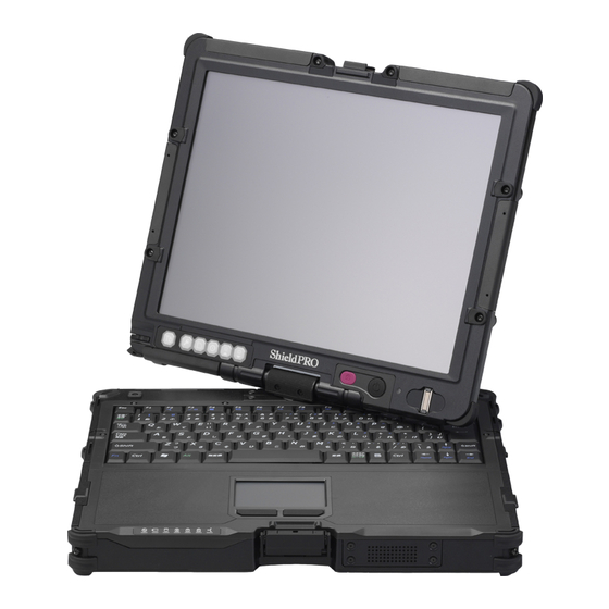
1.3 EXTERIOR VIEW N22A is of convertible type allowing it to be used as a note or tablet PC depending on uses. N22A also has several characteristics including light weight, various security features and installation of touch panel to be user-friendly. On its bottom surface of N22A, the hard disk drive, expanded RAM board and battery pack can be replaced with spares. -
Page 34: Names And Features Of Sections Of N22A
1.3.1 Names and Features of Sections of N22A (1) Inner panels (11) (12) (10) Reference Name Description page LCD display 12.1-in. TFT LCD display (with touch panel) Locks the power switch to prevent the switch from being set Power lock switch unintentionally (enabled by BIOS setting). - Page 35 (2) Outside sections [Rear view] (1) (2) [Bottom view] [Front view] [Right side view] [Left side view] (18) (19) (13) (10) (11) (12) (14) (15) (17) (16)
- Page 36 Reference Name Description page USB connector (2) Connects with a USB device (USB2.0 available). USB connector (3) Connects with a USB device (USB2.0 available). Serial connector Connects with a serial device such as a modem. Antitheft lock Connects with a commercial security cable. Connects with a commercial microphone.
- Page 37 (3) Indicator lamps Name Description While power is supplied to N22A, the lamp illuminates or blinks in several colors depending on the status of N22A or the remaining battery level as follows: Power lamp Illuminating in green: Power-on status ...
-
Page 38: Installation Guide
1.4 INSTALLATION GUIDE From Installing to Operating Steps from installation to operations are shown in the following flow. Chapter 1” Preparation” Introduction ↓ Chapter 1 “Preparation SPECIFICATIONS” Checking installation environment ↓ Chapter 1 “Preparation INSTALLATION GUIDE” Installing/Mounting ↓ Chapter 1 “Preparation INSTALLING BATTERY” Installing the battery ↓... - Page 39 (3) Notes on storage and use environment of N22A 1. N22A is a VCCI Class B information technology equipment (or information equipment mainly intended to be used in household environments) conforming to the reference level of the Voluntary Control Council for Interference by Information Technology Equipment (VCCI).
-
Page 40: Installing Battery
1.5 INSTALLING BATTERY Turn off the N22A and remove the AC adapter or car adapter. Unlock the LCD display to open the LCD panel. See “Opening/Closing LCD Display Panel and Setting Tablet Mode” in “Chapter 2. Uses of N22A”.) While pressing the button of the battery cover on the left side, slide the cover upward to open it. -
Page 41: Installing Ac Adapter
1.6 INSTALLING AC ADAPTER Insert the DC plug of the AC adapter into the power connector on the left side. Connect the attached power cord to the AC adapter. Plug the power cable into the power outlet. Charging of the battery automatically starts. See “Battery”... - Page 42 THIS PAGE INTENTIONALLY LEFT BLANK.
-
Page 43: Chapter 2 Uses Of N22A
Chapter 2 Uses of N22A 2.1 OPENING/CLOSING LCD DISPLAY PANEL AND SETTING TABLET MODE 2.1.1 Opening Panel Pull up latch A and unhook latch B. latch B Unlatch latch B. Pull up latch A. latch A Open the LCD display panel. * LCD display lock consists of latches A and B. -
Page 44: Turning Screen (To Be In Tablet Mode)
2.1.3 Turning Screen (to be in tablet mode) Get the LCD display panel upright. Turn the LCD display panel clockwise by 180º. Do not turn the LCD display panel clockwise by larger than 180º or counterclockwise. Be careful not to pinch your fingers while rotating the LCD display panel. -
Page 45: Turning On/Off Power
2.2 TURNING ON/OFF POWER This section describes how to turn on or off the power of N22A and power saving features (including suspend (standby) and pause states). Take special note on turning off the power. If you turn off the power of N22A improperly, not only data and programs but also the machine itself may be broken. -
Page 46: Turning On Power
2.2.1 Turning on Power To turn on the power in the power-off state, be sure to follow the procedure described below. To turn on the power again, wait for five seconds or longer after power-off. Turn on the peripheral devices. Some peripheral devices may be recognized properly only when their powers are turned on before turning on the power of N22A. -
Page 47: Power Saving Features
Power-off procedure by using Windows End menu Save edited data and quit all the applications. On the Windows® XP screen, click [Start] [Shutdown]. Next, click the [Shutdown] button. Do not press the power switch during the shutdown processing. Check that the power is turned off. After a few seconds, the screen will go dark and the power will turn off automatically. - Page 48 Do not enter the suspend (standby) or hibernate status in the following cases: Executing system change job (including setting driver or adding printer), Outputting data to printer, Replaying audio or motion picture, Reading/writing data from/to memory card or hard disk, ...
- Page 49 Setting power saving feature Perform power saving feature from [Power supply option] of Windows. Operation for manually executing the power saving feature and the time until the machine automatically enter the power saving mode can be set. (1) Changing operation to execute the power saving feature Click [Start] ...
- Page 50 (2) Resuming from suspend (standby) status The following three methods are available. Press the power switch. The power lamp illuminates in green and N22A recovers from the suspend (standby) state (or resumes). Press any key Press any key ...
-
Page 51: Tablet Buttons
2.3 TABLET BUTTONS These buttons enable direct execution of screen rotation, LCD brightness control, etc. Button assignment can be changed as required. (Tb) [Tb] button Tablet button 1 Tablet button 2 Tablet button 3 Tablet button 4 (Tb) (1) (2) Tablet button 5 Label pasting area (1) Operations at depression of buttons... -
Page 52: Keyboard
2.4 KEYBOARD 2.4.1 English Keyboard Using Hot Keys [Fn] Combining Fn with another key allows various operations on N22A to be done easily. These are called hot key features. Some icons indicating the features resulting from combinations of respective keys with Fn are printed on the keys with the same color as Fn. - Page 53 Key combination Feature or description Fn+ScrLK Numeric lock (Num Lk) If these keys are pressed once, the lamp goes on and blue numerals and symbols on keys are enabled. If the keys are pressed again, the lamp goes off and normal characters are enabled.
- Page 54 Entering the euro symbol To enter the euro symbol (€) printed on the 5, change the keyboard layout as described below. Click [Start] [Control Panel]. Click [Date, Time, Language, and Regional Option]. Click the [Details] button under “Text services and input languages” on the [Languages] tab.
-
Page 55: Touch Pad
2.5 TOUCH PAD The touch pad is a pointing device on which you can control the position of the pointer and select a proper button to communicate with N22A. The touch pad is composed of a rectangle pad and two buttons. Moving a finger on the pad allows the pointer on the screen (also called the cursor) to be moved. -
Page 56: Setting Touch Pad
2.5.1 Setting Touch Pad Settings of the touch pad can be changed depending on user needs. For example, left-handed users can interchange the features of the left and right buttons to use the left and right buttons as the right and left buttons in the normal state, respectively. In addition, the size and speed of the pointer on the screen may be changed. -
Page 57: Setting Touch Panel
2.6.1 Setting Touch Panel Setting features You can change the size and speed of the pointer on the screen. For settings, see “Setting Touch Pad.” Settings on the touch pad are also applied to the touch panel. The touch panel cannot be independent of the touch pad. -
Page 58: Display Feature
2.7 DISPLAY FEATURE The display features of N22A are characterized as follows: 12.1-in. TFT (Thin-Film Transistor) color LCD display of resolution 1024×768 XGA (Extended Video Graphics Array) Concurrent display of both LCD display and external monitor Some OSs may limit display modes. 2.7.1 Display Resolution The default resolution and the default number of colors are set at shipment of N22A. -
Page 59: Connecting External Monitor
2.7.3 Connecting External Monitor To get a wide display screen of a higher resolution, an external monitor can be connected to N22A through an external analog RGB monitor connector. Follow the procedure below. Confirm that the power of N22A is OFF. Connect a proper monitor cable to the connector on the external monitor. -
Page 60: Battery
2.8 BATTERY The battery is the power supply built in N22A. The battery can be recharged by using the AC adapter, optional battery charger FC-BC01N or optional car adapter FC-VA01N. Installing the charged battery in N22A allows it to be operated without AC power. The available time of the battery fully charged varies depending on the environment and condition in which N22A is used. -
Page 61: Battery Types
2.8.2 Battery Types Batteries that can be used with the N22A are listed below. Be sure to use a battery of the same type as the selection menu installation type for your N22A. Battery type Description Standard type A lithium-ion battery provided with the FC-N22A (standard model and silicon disk (FC-BP01N)... -
Page 62: Checking Remaining Battery Level
2.8.4 Checking Remaining Battery Level To activate the screen, wait for several minutes before the AC adapter is disconnected from N22A. “Total time remaining” may be different from the actual operation time depending on the operation status of N22A. For Windows XP Click [Start] ... -
Page 63: Replacing Battery
2.8.5 Replacing Battery If a battery of an invalid type is substituted for the old one, it may explode. Always use a spare battery of an option. For used batteries, see “6 Recycling Batteries”. Prepare a new battery valid for the N22A model to be used. ... - Page 64 To protect valuable resources, do not dispose batteries becoming unnecessary, but bring them to any of the following carry-on centers. * For details of the carry-on centers, see the NEC environmental web page below: URL:http://www.nec.co.jp/eco/ja/products/3r/indes_denchi.html (As of May 2008) Notes on handling batteries in recycling...
-
Page 65: Actions Taken For Low Battery Charge Level
2.8.6 Actions Taken for Low Battery Charge Level Decreasing in remaining battery level during battery driving If the battery power remains only a little, the power LED on N22A illuminates in orange or red to inform that the battery should be charged If so, perform either of the following operations depending on situations: ... -
Page 66: Initializing Battery
Charge the battery fully. When the battery is fully charged, the battery LED goes off. Turn on the power of N22A. If the NEC logo screen appears, press F2 to display the BIOS Setup Menu. Unplug the power cord from the AC outlet and remove the AC adapter from N22A. -
Page 67: Pc Card/Express Card
2.9 PC CARD/EXPRESS CARD The cards listed below can be inserted into the N22A: One card of type I or II can be inserted into the PC card slot. One ExpressCard/34 or ExpressCard/54 card can be inserted into the express card slot. 2.9.1 Supporting CardBus The PC card slot on FC-21S conforms to the CardBus specification. -
Page 68: Removing Pc Card From N22A
2.9.3 Removing PC Card from N22A Some PC cards may cause icon [Removing or Taking Out Hardware] to appear on the task tray at the lower right corner of the screen at the connection. Double-click the icon to display the [Safely Remove Hardware] or [Remove Hardware] dialog box. -
Page 69: Memory Card
2.10 MEMORY CARD A triple memory slot is equipped with the N22A supporting the following cards: SD Memory Card (Secured (with copyright protection)) Memory Stick Multimedia Card SDHC Card (Class 6 data transfer speed at 6 MB/sec.) These cards can be used for file storage, data exchange with a device equipped with a card slot (including digital video and digital still cameras), music data writing and substitution for password entry. -
Page 70: Protecting Data
NEC assumes any responsibility for direct and indirect faults including loss of data saved by customers. NEC recommends that, if an SD card is disposed, it is destroyed physically by using such a tool as a hammer to prevent personal data from being flown out. -
Page 71: Fingerprint Sensor
2.11 FINGERPRINT SENSOR (APPLIED TO FS-N22 OF FINGERPRINT SENSOR INSTALLATION MODEL ONLY) N22A of fingerprint sensor installation model can register fingerprint information to enhance security. N22A of no fingerprint sensor installation model cannot be equipped with the fingerprint sensor later. The fingerprint sensor is intended to read fingerprints. -
Page 72: Communication Feature
2.12 COMMUNICATION FEATURE 2.12.1 USB (USB 2.0) USB is the prefix indicating the Universal Serial Bus. The USB has the defined shapes of connectors and allows a computer to connect with up to 127 devices. In addition, the USB provides the plug & play feature to allow the connector of a device to be connected/disconnected without the power of N22A turned off. -
Page 73: Ieee 1394 Devices
2.12.2 IEEE 1394 devices IEEE 1394 devices, such as digital video cameras, can be connected to the N22A. For some devices, driver installation or switch settings may be required before or after connection. Refer to the operation manual for the IEEE 1394 device to be connected before using it. ... -
Page 74: Lan
2.12.3 LAN While N22A operates, do not remove the LAN cable from the hub. If removed, the network connection will be cut out. If the LAN cable is removed during network connection, immediate re-connection may be able to recover the operation. If not, restart OS. ... - Page 75 Power-on using LAN controller When the network server is accessed via an internal LAN, the N22A automatically resumes from the suspend (standby) or hibernate status. When it is off, it is automatically turned on. To use the power-on using LAN controller by the LAN built in N22A, the following settings are required.
-
Page 76: Wireless Lan (Applied To N22A Of Wireless Lan Installation Model Only)
2.12.4 Wireless LAN (applied to N22A of wireless LAN installation model only) N22A of wireless LAN installation model allows the wireless LAN feature to be used. N22A of no wireless LAN installation model cannot be equipped with the wireless LAN feature later. - Page 77 Security enabled by N22A The wireless LAN installed in N22A has the following security features. To provide the following security, used access points should be applicable to the settings. These settings are only intended to reduce security risks as much as possible but do not assure complete safety to avoid security risks.
- Page 78 The features selection screen is displayed. Select the necessary features. To install all sub-features, select “Install this feature and all its sub features” and then click the [Install] button. When the “Installation completed” screen is displayed, click the [OK] button. When the “Restart”...
- Page 79 When “The current package has been changed. Save the changes?” screen is displayed, click [Yes]. The “Save as” screen is displayed. Specify the save destination and file name, and then click [Save]. The “Converting administrator profile to XML” screen is displayed. Click [Browse] to specify the destination, and then click [Close].
- Page 80 Setting SSID feature Perform the following operations. For Windows XP: Select a connectable wireless network in the [Intel® PROSet/Wireless] dialog box and click [Connect]. Enter proper names in fields [Profile Name] and [Wireless Network Name (SSID)]. Click [Next]. The [Security Settings] dialog box appears. Go to “Setting WEP feature”.
- Page 81 Setting encryption feature Perform the following operations. For Windows XP: In the [Security Settings] dialog box, set the settings appropriate for the connected wireless network. Then set the settings follow the directions shown on the display screen.
-
Page 82: Bluetooth Feature (Only For Models With This Feature Installed)
2.12.5 Bluetooth Feature (only for models with this feature installed) This feature allows access to other Bluetooth devices via wireless connection. The communication speed or distance may vary depending on the target Bluetooth device or peripheral conditions, including radio wave environment, barriers, and installation environment. -
Page 83: Hard Disk Drive/Silicon Disk Drive
2.13 HARD DISK DRIVE/SILICON DISK DRIVE The hard disk drives/silicon disk drives shown below can be used with the N22A. Disk type Description Hard disk drive (standard) A hard disk drive provided with the N22A (FC-HD80KN/S) (standard model) Hard disk drive A hard disk drive provided with the N22A (wide temperature range) (wide temperature range model) -
Page 84: Installing/Removing Hdd/Silicon Disks
2.13.1 Installing/Removing HDD/Silicon Disks HDDs are extremely precise equipment. Note the following if used. During data read/write (with the access lamp being ON), only a small shock may cause the HDD to be defected. If the HDD is defected, important data may be unavailable at a time and unable to be restored. It is recommended to frequently back up important data for which the same data cannot be created twice. -
Page 85: Chapter 3 Security
Chapter 3 Security 3.1 SETTING PASSWORD ON BIOS SETUP UTILITY You can set a password intended to limit users of starting the system on the BIOS SETUP Utility. If you set a password, any user must enter the password for the following operations. This can increase the security feature: ... -
Page 86: Login Password
3.2 LOGIN PASSWORD The login password is intended to limit users of OS. If a login password is set, the password must be entered to login to the OS. <Setting Procedure> Click [Start] [Control Panel]. Click [User Accounts] to open the dialog box. Click [Change an account] and click the name of the user for which a login password is to be created. -
Page 87: Fingerprint Authentication Password
3.4 FINGERPRINT AUTHENTICATION PASSWORD (APPLIED TO N22A OF FINGERPRINT SENSOR INSTALLATION MODEL ONLY) The fingerprint authentication password is intended to provide authentication by fingerprints using the built-in fingerprint sensor instead of passwords. N22A has an attached utility to allow logon to Windows, release of screen saver lock and substitution for passwords of various applications by fingerprint authentication. -
Page 88: Chapter 4 Setting Bios
Chapter 4 Setting BIOS This chapter describes the uses of the BIOS SETUP Utility allowing you to set various environmental conditions on N22A including power management. 4.1 BIOS SETUP UTILITY N22A has the BIOS SETUP Utility to set the environment in which N22A is used. In initial booting, the BIOS SETUP Utility is shown in English. -
Page 89: Running/Exiting Bios Setup Utility
4.1.2 Running/exiting BIOS SETUP Utility (1) Starting If the following message appears on the BIOS start screen appearing after the power of N22A is turned on, press F2. Press <F2> to SETUP or Press <F12> to Network boot. Press <F2> to Enter BIOS SETUP, <F12> to Boot on Network. The dialog box shown below appears. -
Page 90: Loading The Bios Setup Defaults
4.1.3 Loading the BIOS SETUP Defaults The following describes the way to return the data on the BIOS SETUP Utility to their factory defaults. Turn on the power of N22A. If message “Press <F2> to SETUP or Press <F12> to Network boot.” or “Press <F2>... -
Page 91: List Of Bios Setup Menus
4.2 LIST OF BIOS SETUP MENUS (1) Main Menu Setting Item Factory Default Setting Item View Only System Time (Current Time) System Date (Current Date) Primary Master (secondary master) SMART Monitoring Enabled Processor Settings CoreMulti-Processing Enabled ――― CPU Speed ――― CPU Type ―――... - Page 92 Setting Item Factory Default Setting Item View Only Silent Boot Logo screen QuickBoot Mode Enabled Fn/Left Ctrl key replacement Disabled...
- Page 93 Setting Item Factory Default Setting Item View Only Tablet Button Tablet Button 1 Tablet Button 2 Tablet Button 3 Tablet Button 4 Tablet Button 5 [Tb] + Tablet Button 1 [Tb] + Tablet Button 2 [Tb] + Tablet Button 3 [Tb] + Tablet Button 4 [Tb] + Tablet Button 5 DMI Event Logging...
- Page 94 (4) Power Management Configuration View Only Setting Item Factory Default Setting Item Power Switch Lock Disabled Wake On LAN Disabled Wake On PC Card Disabled Wake On ExppressCard Disabled Wake On Ring Disabled Restore On AC/Power Loss Stay Off Restore On AC/Power Loss from S4 Disabled C-States Enabled...
-
Page 95: Main Menu
4.3 MAIN MENU (1) System Time Enter the current time in format “hh:mm:ss” (hh: hour, mm: minute and ss: second) (2) System Date Enter the current date in format “yyyy/mm/dd” (yyyy: year, mm: month and dd: date) (3) Primary Master (Secondary Master) Indicates the information on devices connected to the primary master (including capacities and types). -
Page 96: Advanced Menu Configuration
Set to [POST screen] to display the Power-On Self-Test Logo screen (POST) screen without displaying the NEC logo. Non screen Set to [Logo screen] to display the NEC logo and shorten the booting time. Set to [Non screen] to display neither the POST nor NEC logo screens. - Page 97 (8) Tablet Button This option allows you to assign features to the tablet buttons. If you move the cursor to this option and press Enter, the relevant setting submenu appears on the screen. For the submenu, see “4.3.4 Tablet Button Submenu”. (9) DMI Event Logging This option displays the system event log occurring on booting or allows you to set the system event log.
-
Page 98: Pci Configuration Submenu
4.4.2 PCI Configuration Submenu The PCI Configuration Submenu allows you to set features of PCI devices built in N22A. Option Parameter Description On Board LAN Provide settings for on-board LAN devices. If you move the cursor to this option and press Enter, the relevant setting submenu appears on the screen. - Page 99 Option Parameter Description Display Out Specify the monitor(s) on which screen data is displayed. LCD + CRT Set to [CRT] to display screen data on the external monitor in booting. (Screen data is not displayed on the built-in LCD monitor.) Set to [LCD] to display screen data on the built-in LCD monitor in booting.
- Page 100 Option Parameter Description Reset Configuration Data Summary Screen Silent Boot QuickBoot Mode Fn/Left Ctrl Key replacement...
-
Page 101: Tablet Button Submenu
4.4.4 Tablet Button Submenu The Tablet Button Submenu allows you to assign features to tablet buttons. Option Parameter Description Tablet Button 1 Assign features to tablet buttons. 00h ~ FFh Enter the key codes to be set. Tablet Button 2 Key codes shown in the table below are only Tablet Button 3 available... -
Page 102: Security Menu
4.5 SECURITY MENU The N22A can limit the BIOS Setup Menu users by setting a supervisor password and user password, and prevent unauthorized use of the hard disk drive with other than the main unit by setting a hard disk password. 4.5.1 Security (1) Supervisor Password This option indicates whether a supervisor password is set or not. - Page 103 (4) Set User Password This option allows you to set a user password. If a user password is set, accessing to the system on booting is limited. Without supervisor password, you cannot select an item to set the user password. First set the supervisor password.
- Page 104 (7) Network Boot Setting The option allows you to provide settings on network starting. If you move the cursor to this option and press Enter, the relevant setting submenu appears on the screen. Option Parameter Description Keyboard/Mouse Lock Disabled Allows you to set the operations of the keyboard and Enabled mouse on remote (PME) booting (until OS is started).
- Page 105 Supplement 2: Erasing HDD data The following shows the erase HDD data procedure. NSA (Random(1) Random(2) 00h) Writes [random data random data 00] in the order in the entire HDD area. The erase HDD procedure conforms to the method recommended by NSA. Erasure takes 80 to 140 minutes for a standard HDD (80 GB), 25 to 30 hours for a wide temperature range HDD (80 GB), and 5 to 6 hours for a silicon disk (20 GB).
- Page 106 (10) Security Chip Configuration This option allows you to provide settings for the security chip. If you move the cursor to this option and press Enter, the relevant setting submenu appears on the screen. If the security chip is set to Enabled, set supervisor and user passwords to limit accessing to the BIOS SETUP Utility.
-
Page 107: I/O Lock Feature
4.5.2 I/O Lock Feature The I/O lock disables the I/O feature, measures to interchange data with external devices, on the BIOS SETUP Utility. I/O lock can be enabled by setting the following in the BIOS Setup Menu. (1) How to lock the LAN controller [Advanced] ... -
Page 108: Power Management Configuration
4.6 POWER MANAGEMENT CONFIGURATION 4.6.1 Power Management Configuration This menu allows you to set power management features. Option Parameter Description Power Switch Lock Disabled Specify whether the power inhibit release switch is enabled Enabled or disabled. Set to [Enabled] to enable the power switch with the power inhibit release switch being pressed. - Page 109 Option Parameter Description Battery Charge Mode Normal Specify the battery charging mode. LongLife Set to [Normal] to charge the battery fully. Keeping Set to [LongLife] to charge the battery at level of 80%. (Select this if you want to make the battery life longer.) Auto Set to [Keeping] to charge the battery at level of 50%.
-
Page 110: System Menu
4.7 SYSTEM MENU The System Menu allows you to set system features as described in the table below. Option Parameter Description System Management Indicates system information. If you move the cursor to this option and press Enter, the relevant setting submenu appears on the screen. System Part # (View only) Indicates the product name of N22A. -
Page 111: Boot Menu
4.8 BOOT MENU 4.8.1 Boot Order Configuration This menu lists boot devices in the preference order. The top device first tries to start the OS. If the device cannot start the OS due to such a reason as no existence of OS, the next device tries to start the OS. -
Page 112: Chapter 5 Installing Os And Applications
Chapter 5 Installing OS and Applications 5.1 WINDOWS XP PRE-INSTALLED MODEL 5.1.1 Configuration of Windows XP Pre-installed Model N22A of Windows XP pre-installed model has Microsoft Windows XP Professional installed at factory shipment to be automatically booted at power-on. The parameters are previously set to the factory defaults as shown in the table below. Accordingly, you may not enter them on booting of N22A. - Page 113 Note that Windows XP installed in N22A is not specified as an upgrading/downgrading product by Microsoft. The following warning may be recorded in the event log at the time of log-off, this is only an indication and the operation of OS is not affected. Event ID : 1517 Source...
-
Page 114: Microsoft Windows Xp Service Pack 2
(1) Registry change procedure 1. Start WindowsXP. 2. Click [Start] [Run…], type “c:¥windows¥regedit.exe”, and click [OK]. 3. Open HKEY_LOCAL_MACHINE¥SOFTWARE¥Microsoft¥Windows NT¥CurrentVersion. 4. Click the following items and change the organization and/or owner. Registered Organization Registered Owner 5. Click [File] [Exit] to exit the registry editor. (2) Organization/owner check procedure 1. -
Page 115: Installing Attached Applications
5.2 INSTALLING ATTACHED APPLICATIONS Be sure to log in as a user having an Administrator privilege, to add or remove applications. An administrator privilege is a privilege to manage the entire configuration of a computer. If you are unsure how to log in as a user with an administrator privilege, on the [Logon information] screen, enter “Administrator”... - Page 116 (2) Supported Operating Systems Microsoft ® ® Windows XP Japanese Version (SP2) Microsoft ® ® Windows XP English Version (SP2) (3) How to Install Start Windows. Click [Start] [Control Panel]. Double click [Add/Remove Programs]. Click the [CD or Floppy Disk (F)] button in the [Add Program] tab. Click the [Next] button in the [Install from Floppy Disk or CD-ROM] window.
-
Page 117: Software Ras Tool
5.2.2 Software RAS Tool CD-ROM/DVD drive unit is not required because the “Set of Installation Software” is stored on Drive C (hard disk). ® Windows Vista is not supported. (1) Overview This tool monitors hardware status and SMART information of the hard disk, and records in log files, outputs to Windows Event Viewer, and starts specified programs when an abnormality causing failures is detected. -
Page 118: Adobe Reader 7.0
® ® 5.2.3 Adobe Reader CD-ROM/DVD drive unit is not required because “Set of Installation Software” is stored on Drive C (hard disk). This software is not included with Linux Pre-installation models. (1) Overview Display, view, and print electrical manuals in PDF (Portable Document Format) format. ®... -
Page 119: Fingerprint Authentication Utility (Only Models With This Feature)
(3) How to start Click [Start] [Programs] [Adobe Reader 7.0]. ® ® Adobe Reader 7.0 window appears. (4) How to delete Start Windows. XP: Click [Start] [Control Panel]. ® For Windows ® For Windows XP: Double-click [Add/Remove Programs]. Click “Adobe Reader 7.0”... - Page 120 (3) Usage Start Windows. Click [Start] [Settings] [Control Panel]. Double-click [Add or Remove Program]. Click [CD or Floppy] on the [Add new Programs] tab. If message “Install Program From Floppy Disk or CD-ROM, and then click Next.” appears, click [Next]. Click [Browse…], specify “C:¥WINXP¥Fingerprint Sensor¥autorun.exe”...
-
Page 121: Infineon Security Platform
To use the security chip, set supervisor and user passwords to restrict accessing to the BIOS SETUP Utility. See “SECURITY MENU” in “Chapter 4 Setting BIOS”. After power-on of N22A, the BIOS start screen (with NEC logo displayed at the center) appears. If message “Press <F2> to SETUP or Press <F12> to Network boot.”... - Page 122 (3) Installation procedure Start Windows. Just after BIOS setting, the hardware add wizard requests driver installation. However, the driver can be installed in the following procedure. you may cancel the hardware add wizard. Click [Start] [Settings] [Control Panel]. Double-click [Add or Remove Program].
-
Page 123: Fc Button Setting Tool
5.2.6 FC Button Setting Tool Two sets for executing desired applications can be registered to abbreviation keys. (1) Supporting OSs Microsoft Windows XP, English Ver. (SP2) (2) Usage The registered applications can be executed by Fn+1 (FC button 1) and Fn+2 (FC button 2), respectively. -
Page 124: Other Oss And Applications
5.3 OTHER OSS AND APPLICATIONS (1) CD-R/RW with DVD-ROM drive Option FC-CW002U (external CD-R/RW with DVD-ROM drive) contains writing tool. A DVD video replay tool is commercially available. (2) English version preinstalled model The procedure for re-setup using the accompanying recovery DVD-ROMs is the same as ®... - Page 125 THIS PAGE INTENTIONALLY LEFT BLANK.
-
Page 126: Chapter 6 Maintenance
Is N22A booted normally? If the NEC Logo screen does not appear (excluding the case where BIOS is set not to display the NEC Logo screen) or message “Operating system not found” appears in N22A booting, a hardware error may occur. - Page 127 Reinstall the OS according to the description in “Chapter 5 Installing OS and Applications” and check if N22A operates normally. Reinstalling OS causes applications installed by you and data created by you to be erased. Not soluble Solved Contact your sales agent or NEC.
-
Page 128: Actions Taken To Solve Trouble (Tips)
6.1.2 Actions Taken to Solve Trouble (Tips) Because N22A uses combinations of various applications and peripherals, unexpected troubles can occur. The following describes tips to solve troubles appropriately. Take proper actions calmly. Neither turn off the power nor click the mouse hastily. If N22A seems to freeze, it may only take much time to process applications. - Page 129 Contact NEC. For NEC inquiries, see “Maintenance Service” in this chapter. Before inquiring, enter the failure symptoms on the “Problem Check Sheet” at the end of this manual. The warranty card includes the model number and other information useful for remedies, so have it handy for reference.
-
Page 130: Troubleshooting Q&A
6.1.3 Troubleshooting Q&A (1) Troubles including smoking, heat generation, noise and cable disconnection Symptoms Action Smoke and/or odors are generated from N22A. Turn off the power immediately. Unplug the AC cord from the mating N22A is heated too hot to make hands contact AC outlet, disconnect the AC adapter from N22A and remove the battery from N22A. - Page 131 For the battery removal procedure, see “Replacing Battery”. If the power cannot be turned on still, N22A may be defected. Contact your service representative or NEC. First follow the procedure in “Turning off power”. If the power cannot The power cannot be turned off. It is desired to turn off the power forcibly.
- Page 132 (3) AC adopter troubles Symptoms Action Power is not supplied even though the AC adapter It is the voltage error if the power lamp is blinking in red and green is connected. The power lamp blinks red. alternately at 0.5-second intervals. Stop using the AC adapter and contact your dealer.
- Page 133 (6) Troubles of HDD Symptoms Action After power-on, N22A does not recognize the Confirm that the type of the HDD is configured properly on the BIOS HDD. Setup Menu. Insert the bootable disk to the external 3.5-in. floppy disk drive or An error message on the HDD appears on the display screen.
- Page 134 (8) Troubles of keyboard, mouse and touch pad Symptoms Action The keyboard does not respond to any inputs. Connect an external USB keyboard to N22A and check if the keyboard can operate properly. If so, the built-in keyboard cable may be defected.
- Page 135 Pressing F12 cannot make network booting. Pressing F12 on the NEC logo screen may not be able to run the network boot process. In this case, press F12 on the NEC logo screen several times. If the network boot process is not executed still, change the interval at which F12 is pressed.
- Page 136 Symptoms Action If a microwave oven is used in an area where communication with Communication is disabled intermittently or the communication speed is too late. 2.4 GHz wireless LAN device occurs, the communication speed and distance of the 2.4 GHz wireless LAN device may be reduced. It is recommended that microwave ovens are not used near 2.4 GHz wireless LAN devices.
- Page 137 (12) Troubles of PC card Symptoms Action Confirm that the PC card is inserted properly. The PC card does not operate. If the card requires an IRQ, confirm that at least a single IRQ is not used. The PC card provides communication improperly. The relevant application might be reset when N22A was entered into the suspend (standby) or pause state.
- Page 138 (14) Software troubles Symptoms Action Confirm that the application program is installed properly. An application program operates improperly. If an error message appears on the display screen, refer to the documentation of the application program to search for required information.
- Page 139 (16) Troubles of optional CD-R/W with DVD-ROM drive FC-CW002U Symptoms Action Confirm that the CD is properly put on the tray with the label facing The CD-R/W with DVD-ROM drive does not read CD data. upward. Confirm that the CD is not dirt. If dirt, clean the CD with CD cleaning kit.
- Page 140 Contact your service representative. It is desired to use N22A in other than Japan. Contact your service representative. NEC does not provide any maintenance service in countries and regions other than Japan.
-
Page 141: Re-Setup Of Windows Xp In N22A Of Pre-Installed Model
6.2 RE-SETUP OF Windows XP IN N22A OF PRE-INSTALLED MODEL 6.2.1 Re-setup Re-setup can recover the damaged system of N22A to the normal state. However, files stored in the HDD are erased. In addition, it takes much time for re-setup. Check if re-setup is absolutely required before starting the job. -
Page 142: Standard And Custom Re-Setups
6.2.2 Standard and Custom Re-setups There are two re-setups, or standard and custom re-setups. The following describes four re-setup patterns. (1) Standard re-setup Every hard disk drive in N22A can be returned to the factory default. Beginners and users unfamiliar with HDD should always follow the procedure for re-setup. (2) Custom re-setup For re-setup of drive C only or change of the capacity of drive C, follow the procedure. -
Page 143: Repairing System
6.2.3 Repairing System The following describes the troubleshooting procedures when the system cannot be started normally due to change of system configuration. Repairing System by Using Configuration in the Last Normal Starting If starting Windows XP is disabled after some system change, the problem can be solved by using the configuration in the last normal starting. -
Page 144: Standard Re-Setup
6.2.4 Standard Re-setup Repairing System by Using Recovery CD-ROMs The Recovery CD-ROMs attached to N22A can be used to recover the information stored in the HDD to factory defaults. Separate “Recovery DVD-ROM Media” for Japanese and English version preinstalled models are included one copy for each. - Page 145 If the following dialog box appears, select [標準再セットアップモード(強く推 奨)] and press Enter. Follow the direction on the dialog box to provide re-setup. For the subsequent steps, follow the directions on the dialog box. Now the HDD is completely restored to the factory defaults. Then provide re-setup for Windows XP.
- Page 146 (The following describes the operation after you select [No].) Click [Next]. Message “Checking your Internet connectivity” appears and then message “How will this computer connect to the Internet?” appears. Click [Skip]. Message “Ready to register with Microsoft” appears. Select “No, not at this time” here. Click [Next].
- Page 147 (6) Notes on change to keyboard or mouse of different key layout If the current keyboard or mouse is changed to another one, the new keyboard or mouse may operate improperly. If so, change the key layout of the keyboard in the following procedure: Click [Start] ...
-
Page 148: Custom Re-Setup
6.2.5 Custom Re-setup The HDD can be restored to specified status by using the attached Recovery CD-ROMs. Checking Items (1) Tools to be prepared The following tools are required for re-setup by using the recovery CD-ROMs. Prepare the following CD-ROMs attached to N22A. ... - Page 149 If the following dialog box appears, select [カスタム再セットアップモード] and press Enter. The following dialog box appears. Select one of the following three procedures. (1) [C ドライブのみを再セットアップ] (2) [全領域を 1 パーティションにして再セットアップ] (3) [ユーザ設定による再セットアップ] (1) Re-setup of drive C only (NTFS) If the HDD to be subject to re-setup has an unassigned area larger than drive C, re-setup of drive C only may be disabled.
- Page 150 (2) Re-setup by combining entire area into a single partition (NTFS) Select [全領域を 1 パーティションにして再セットアップ] on the [WindowsXP 再セット アップ] dialog box and press Enter. If the following dialog box appears, select [全領域を 1 パーティションにして再 セットアップ] and press Enter. If message “ハードディスクの全領域をフォーマットして Windows XP を再セッ トアップします。よろしいですか?”...
-
Page 151: Maintenance Service
If the FC-NOTE Series ShieldPRO (FC-N22A) fails, two ways are available for transferring it to and from the repair center: either a courier assigned by NEC can collect the device and return it after the repair (pick-up repair) or the customer can take the failed device to our repair center for repair and collect the repaired device from the repair center (delivery repair). -
Page 152: Consumables And End-Of-Life Products
For replacement of components, contact your dealer. The following data pertain to the replacement intervals recommended by NEC. The values were calculated at standard conditions with an ambient temperature of 25ºC. Note that the values are not guaranteed. -
Page 153: Service Menu
A service engineer visits the installation site and repairs the system when a problem occurs. 2) Pick-up repair service A company assigned by NEC picks up the device and delivers the repaired one. 3) Delivery repair service The customer sends the device with a failure to our repair center for repair. -
Page 154: Failure Or Abnormality
Notes of message on the display device Failure information (Problem check sheet at the end of this document) * NEC shall not be held responsible for the data stored in the hard disk. Make a backup copy of data stored in the hard disk. -
Page 155: Care
Lithium ion batteries are valuable resources being recyclable. To protect valuable resources, do not dispose batteries becoming unnecessary but bring them to any of the following carry-on centers: * For details of the carry-on centers, see the NEC environmental web page below: URL:http://www.nec.co.jp/eco/ja/products/3r/indes_denchi.html ... -
Page 156: Carriage And Storage Of N22A
6.7 CARRIAGE AND STORAGE OF N22A Follow the procedure below if N22A will be carried or stored. Back up important data stored in the hard disk. Close all the covers during transportation. Turn off the power of N22A. Disconnect the AC adapter from the mating receptacle. - Page 157 THIS PAGE INTENTIONALLY LEFT BLANK.
-
Page 158: Chapter 7 Appendices
Chapter 7 Appendices 7.1 I/O INTERFACES (1) PCMCIA interface Connector: 68-pin card slot Pin number Signal name Pin alignment CADATA<3> CADATA<4> CADATA<5> CADATA<6> CADATA<7> CE1# CADR<10> CADR<11> CADR<9> CADR<8> CADR<13> CADR<14> IREQ# CAVCC CAVPP CADR<16> CADR<15> CADR<12> CADR<7> CADR<6> CADR<5> CADR<4>... - Page 159 Pin number Signal name Pin alignment CADR<22> CADR<23> CADR<24> CADR<25> RESET WAIT# INPACK# REG# SPKR# CHSTS# CADATA<8> CADATA<9> CADATA<10> CD2# (2) Express card interface Pin number Signal name Pin alignment USBD- USBD+ CPUSB# RESERVED RESERVED SMBCLK SMBDATA +1.5V +1.5V WAKE# +3.3VAUX PERST# +3.3V...
- Page 160 (4) LAN interface (1000BASE-T) Connector: RJ45 Pin number Signal name Pin alignment LA_TRD0+ LA_TRD0- LA_TRD1+ LA_TRD2+ LA_TRD2- LA_TRD1- 8 • • • 1 LA_TRD3+ LA_TRD3- (5) DC plug jack Connector: RJ11 Pin number Signal name Pin alignment ADP-IN AC-GND AC-GND (6) Headphone output interface Pin number Signal name...
- Page 161 (9) Serial interface (COM1) Connector: D-sub 9-pin connector (male) Pin number Signal name Pin alignment 1 • • • 5 6 • • 9 (10) USB interface (USB 1/2/3) Pin number Signal name Pin alignment (11) IEEE1394 interface Pin number Signal name Pin alignment TPB-...
-
Page 162: Interrupt Levels
7.2 INTERRUPT LEVELS The table below lists interrupt levels. Interrupt levels 0 to 23 are assigned. A smaller interrupt level has a higher priority. List of assignment levels Interrupt level Setting at shipment from factory IRQ00 Counter/timer IRQ01 Keyboard (PS/2) IRQ02 Interrupt controller IRQ03... -
Page 163: Outside Dimension
7.3 OUTSIDE DIMENSION 7.3.1 N22A (1) Body 298.6 (295.4 excluding projections and bumper) - Page 164 [Rotation of LCD display panel] Unit: mm * Excluding projections (including rubber feet and protect rubbers at 4 corners) [Body with LCD display panel made upright (node type)]...
-
Page 165: Spare Battery (Fc-Bp01N, Fc-Bp01N/W, Fc-Bp01N/L)
[Body with LCD display panel taken down] 483.4 * Excluding projections (including rubber feet and protect rubbers at 4 corners) Unit: mm 7.3.2 Spare Battery (FC-BP01N, FC-BP01N/W, FC-BP01N/L) 20.5 100.69 Unit: Weight: about 0.33 kg(FC-BP01N) about 0.33 kg(FC-BP01N/W) about 0.21 kg(FC-BP01N/L) -
Page 166: Ac Adapter (Fc-Aa01N)
7.3.3 AC Adapter (FC-AA01N) * Excluding projections ±0.5 ±0.5 ±100 2,000 Unit: Weight: about 0.46 kg cabl ut 2 leng cord leng 7.3.4 Hard Disk Drive (Standard HDD:FC-HD80KN-S, Wide Temperature HDD:FC-HD40KN-S)/ Silicon Disk Drive (FC-SD20KN-S) Unit: Weight: about 0.12Kg (FC-HD80KN-S) about 0.12Kg (FC-HD40KN-S) about 0.12Kg... - Page 167 Problem check sheet When making an inquiry, you will be asked the configuration of the product in use and specific conditions of the problem. Before inquiring, complete each item of this sheet, which will lead to a prompt and appropriate response.
- Page 168 Software Version of OS □ Windows XP Professional (ServicePack Application(s) running while the failure occurred Problem Check Sheet 2 Specific failure details What failed? Describe the failure. Did any error messages or numbers appear on the screen? If any appeared, write the message(s) or the number(s).
- Page 169 NEC will confirm the following when receiving your repair request. To eliminate any problem related to repair, complete all of the following items. If the configuration of peripheral devices for repair is different from that written in Problem Check Sheet 1, enter the following.
-
Page 170: Index
INDEX AC adapter············································10 LCD display ··········································12 APPLICATION ·········································· MAINTENANCE········································ BATTERY ·············································33 MEMORY CARD ······································ BIOS ·····················································59 BIOS SETUP UTILITY ··························59 Bluetooth··················································· Pause state···········································13 PC CARD/EXPRESS CARD·················38 PCI Configuration ·································66 Checking Remaining Battery Level ·······34 Power lamp···········································14 COMMUNICATION FEATURE ·············43 Power Saving Features ························13 Connecting External Monitor·················31 Primary Master ·····································65 Convertible type······································2... - Page 173 User’s Manual NEC Factory Computer FC-NOTE Series N22A Ver. 1 May 2008 AM1-000859-001...
Need help?
Do you have a question about the ShieldPRO N22A and is the answer not in the manual?
Questions and answers