Table of Contents
Troubleshooting

Related Manuals for Johnson Matrix Retail R30


Summary of Contents for Johnson Matrix Retail R30
- Page 1 Issue date Edition Doc No. SM-TM-AF-011 2017-3-1 JOHNSON Revision Edition time Page date Johnson Industries (Shanghai) Co.,Ltd R30 & R50 Service Manual Document Approval Review Editor Alex Tang Dora Kyle. Schweitzer...
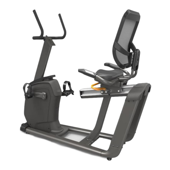
- Page 2 Product Browse Matrix Retail R30 Matrix Retail R50 Specification Model Name Frame Frame Type New recumbent frame New recumbent frame Pedal Type Ratcheting Closure Ratcheting Closure *JD1A-B *JD-62A - Blue Handle Bar Adjustment Handle Bar Type Seat - Painted Seat - Painted...
-
Page 3: Table Of Contents
Contents CHAPTER 1: SERIAL NUMBER LOCATION ....................5 CHAPTER 2: CONSOLE INSTRUCTION 2.1 XR/XIR/XER CONSOLE ........................6 2.2 OPERATION GUIDE ........................... 6 2.3 CONSOLE DESCRIPTION-XR ......................7 2.4 4 SOFTWARE UPDATING ........................9 2.5 CONSOLE DESCRIPTION- XER/XIR ....................9 CHAPTER 3: TROUBLESHOOTING 3.1 ELECTRICAL DIAGRAM-CONSOLE .................... - Page 4 3.4.7 TROUBLESHOOTING – NO RESISTANCE OR INCORRECT RESISTANCE ......19 3.4.8 TROUBLESHOOTING – HEART RATE ISSUES..............21 3.4.9 TROUBLESHOOTING-HANDLEBAR KEYPAD ISSUE…………………………………………….22 CHAPTER 4: PART REPLACEMENT GUIDE CONSOLE REPLACEMENT ......................23 HANDLEBAR REPLACEMENT ....................... 24 PEDAL REPLACEMENT ......................... 24 CRANK REPLACEMENT ........................ 25 SIDE COVERS REPLACEMENT .....................
-
Page 5: Chapter 1: Serial Number Location
CHAPTER 1: Serial Number Location 1.1 Serial Number Location MATRIX R30/R50 BIKE FRAME... -
Page 6: Chapter 2: Console Instruction
CHAPTER 2: Console Instruction 2.1 XR/XIR/XER CONSOLE 2.2 OPERATION GUIDE... -
Page 7: Console Description-Xr
CHAPTER 2: Console Instruction 2.3 CONSOLE DESCRIPTION-XR XR CONSOLE DESCRIPTION Note: There is a thin, protective sheet of clear plastic on the overlay of the console that should be removed before use. A) LCD DISPLAY WINDOW: Displays workout feedback, program profile and more. B) GO/PAUSE: Press to start, pause or resume your workout. - Page 8 CHAPTER 2: Console Instruction 2.3CONSOLE DESCRIPTION-XR-CONTINUED ENTER: Confirm each program setting. Press to change display feedback during workout. Press and hold to scan. E) ARROWS: Used to adjust program settings. F) NUMBER KEYPAD: Used to enter XID login or program data during program setup. Also used to adjust speed/resistance level during workout.
-
Page 9: Software Updating
CHAPTER 2: Console Instruction 2.4 Software Updating Update console software with the software updating tool. Load the software update onto the USB flash drive. Insert the USB flash drive into the USB port; the console will update automatically. c. If the software has updated successfully, the console will start initial setup and display the software version. SB flash drive Remove the U 2.5CONSOLE DESCRIPTION-XER/XIR... - Page 10 CHAPTER 2: Console Instruction F) HEADPHONE JACK: Plug your headphones into the console to use them instead of the console speakers. G) AUDIO IN: Plug your media player into the console using the included audio adaptor cable. H) ENERGY SAVER LIGHT: Indicates if machine is in energy saver mode. Press a speed/incline/resistance button to wake up the machine.
-
Page 11: Chapter 3: Troubleshooting
CHAPTER 3: Troubleshooting 3.1ELECTRICAL DIAGRAM-CONSOLE 3.1.1 XR CONSOLE DIAGRAM 3.1.2 XER/XIR CONSOLE DIAGRAM... -
Page 12: Electrical Diagram-Frame
CHAPTER 3: Troubleshooting 3.2 ELECTRICAL DIAGRAM-FRAME 3.2.1 R30 FRAME WIRING SCHEMATIC... -
Page 13: R50 Frame Wiring Schematic
CHAPTER 3: Troubleshooting 3.2 ELECTRICAL DIAGRAM-FRAME-CONTINUED 3.2.2 R50 FRAME WIRING SCHEMATIC... -
Page 14: Ecb/Lcb Wiring Instructions
CHAPTER 3: Troubleshooting 3.3 ECB/LCB WIRING INSTRUCTIONS 3.3.1 ECB WIRING INSTRUCTIONS (R30) N1------- Power light N2------- Speed sensor cable socket Console set cable socket N3------- Console cable... - Page 15 CHAPTER 3: Troubleshooting 3.3 ECB/LCB WIRING INSTRUCTIONS 3.3.2 MCB WIRING INSTRUCTIONS (R50) N1------- Power light N2------- Speed sensor cable socket Console set cable socket N3------- Console cable N4 ------ Generator / Induction Brake/Magnet...
-
Page 16: No Power To The Console
CHAPTER 3: Troubleshooting 3.4 TROUBLE SHOOTING 3.4.1 TROUBLESHOOTING – NO POWER TO THE CONSOLE Symptom: Console does not light up. Possible Reason: a. The power adaptor is not correct or is defective. b. The console cable has a bad connection or is defective. c. -
Page 17: Troubleshooting -No Hand Pulse Response
CHAPTER 3: Troubleshooting 3.4.2 TROUBLESHOOTING –SPEED DOES NOT DISPLAY---CONTINUED Remove the side cover and check to see if the sensor wire is firmly connected. 3. Check to see if one corner of the sensor is aligned with the magnet and that the distance is less than 5mm. -
Page 18: Troubleshooting - Radio Frequency Issues
CHAPTER 3: Troubleshooting 3.4.5 TROUBLESHOOTING – RADIO FREQUENCY ISSUES Symptom: The Radio Frequency Board (RF Board) cannot connect with Passport. Possible Reason: a. The Passport keys are not functional. b. The FFC wire is damaged or disconnected. c. The console is defective. Solution: Make sure that the Passport keys are functional. -
Page 19: Troubleshooting -No Rpm Displayed
CHAPTER 3: Troubleshooting 3.4.6 TROUBLESHOOTING –NO RPM DISPLAYED Symptom: No RPM shown on the console. Possible Reason: a. Bad connection between the console cable and the console, or a damaged cable. b. The speed sensor wire is damaged or not working. c. -
Page 20: Troubleshooting - No Resistance Or Incorrect Resistance
CHAPTER 3: Troubleshooting 3.4.7 TROUBLESHOOTING – NO RESISTANCE OR INCORRECT RESISTANCE 1. General information: Symptom Possible Cause Test Procedure Repair Verify that the tension Tension cable is not connected cable is connected to the Reattach cable. to the brake or has failed break or has not failed. - Page 21 CHAPTER 3: Troubleshooting Solution: a. Check if the console shows RPM value. If it does not, refer to troubleshooting for NO RPM DISPLAYED in Section 3.4.6 b. Remove the front shrouds. Turn on the console, and check the ECB motor. At resistance level 1, the head of the steel rope should point towards the top right side (around 45 degrees –...
-
Page 22: Troubleshooting - Heart Rate Issues
CHAPTER 3: Troubleshooting 1. Check the Connection wire between consoles to MCB. Try to unplug and then plug in the connector (Page 14, CN2); 2. Check the connection wire between MCB and Induction Brake/Magnet Try to unplug and then plug in the connector (Page 14, CN4);... -
Page 23: Troubleshooting-Handlebar Keypad Issue
CHAPTER 3: Troubleshooting Solution: Remove the 2 screws holding the 2 halves of the heart rate grip together and check to make sure it is firmly connected, with no breaks. b. Check continuity of the HR grip wiring. Place one terminal of a multi-meter set for resistance on the HR grip wiring at the HR grip, and the other terminal on the HR grip wiring at the console. -
Page 24: Chapter 4: Part Replacement Guide
CHAPTER 4: Part Replacement Guide 4.1 CONSOLE REPLACEMENT 1) Remove the 5 screws holding the console back cover to the frame (Figure A). 2) Remove the 4 screws holding the console to the frame (Figure B). 3) Disconnect the console cable and HR connections from the defective console and remove the console (Figure C). -
Page 25: Handlebar Replacement
CHAPTER 4: Part Replacement Guide 4.2 HANDLEBAR REPLACEMENT 1) Remove the 2 screws holding the handlebar. (Figure A). 2) Install a new handlebar. FIGURE A 4.3 PEDAL REPLACEMENT 1) Loosen and remove the screw holding the pedal to the crank (Figure A). 2) Install a new pedal. -
Page 26: Crank Replacement
CHAPTER 4: Part Replacement Guide 4.4 CRANK REPLACEMENT 1) Loosen and remove the screw holding the crank to frame (Figure A). 2) Install a new crank. FIGURE A 4.5 SIDE COVERS REPLACEMENT 1) Remove the two top covers by hand (Figure A and B) 2) Remove the mast by removing the four screws. - Page 27 CHAPTER 4: Part Replacement Guide 4.5 SIDE COVERS REPLACEMENT---CONTINUE 3) Remove the top cover by loosening and removing the four screws. (Figure D and E) FIGURE D FIGURE E 4) Remove crank arm (see section 4.4) 5) Remove the crank by loosening and removing the four screw. (Figure F and G) FIGURE F FIGURE G 5) Remove the side cover by removing the 7 screws on both the left and right side covers.
-
Page 28: Mcb Replacement
CHAPTER 4: Part Replacement Guide 4.6 MCB REPLACEMENT 1) Remove side cover (see section 4.5) 2) Remove the LCB by removing the 2 screws (Fig A). 3) Install a new LCB. (Fig B) 4) Reverse step 1 Fig A Fig B Note: Wear an ESD strip when handling and installing the MCB. -
Page 29: Stabilizer Covers Replacement
CHAPTER 4: Part Replacement Guide 4.7STABILIZER COVERS REPLACEMENT 1) Remove the front stabilizer by removing the two screws underneath the frame (Figure A) 2) Remove the 4 screws to remove the central cover (Figure B). 3) Reverse the steps to install a new cover. FIGURE A FIGURE B 4.8 CUP HOLDER REPLACEMENT... -
Page 30: Heart Rate Wire Replacement
CHAPTER 4: Part Replacement Guide 4.9 Heart rate replacement 1) Remove the 3 screws (Figure A & Figure B). 2) Gently pull out the heart rate wire (Figure B). 3) Reverse the steps to install a new heart rate wire. 4) Connect the heart rate wire to the console by following the path shown from A to B (FIGURE-D) FIGURE A FIGURE B... -
Page 31: Seat Replacement
CHAPTER 4: Part Replacement Guide 4.10 SEAT REPLACEMENT 1) Remove the 4 screws to disassemble the back cover (Figure A) and then remove the seat mast (Figure 2) Install a new seat. FIGURE A FIGURE B... -
Page 32: Adjustment Bar Replacement
CHAPTER 4: Part Replacement Guide 4.11 ADJUSTMENT BAR REPLACEMENT 1) Remove the 2 screws to disassemble the front cover (Figure A) and or the back cover (Figure B). FIGURE A FIGURE B 2) Remove the (front or rear) 2 screws corresponding to step one (Figure C and D). 3) Reverse the steps to install a new adjustment bar. -
Page 33: Drive Belt Replacement
CHAPTER 4: Part Replacement Guide 4.12. DRIVE BELT REPLACEMENT 1. REMOVE SIDE COVER (SEE SECTION 4.5) 2. Put the drive belt on the wheel (FIGURE-A) FIGURE A 3. Measure belt tension that it should be 200HZ -220HZ (FIGURE-B) FIGURE B 4. - Page 34 CHAPTER 4: Part Replacement Guide 4.13 .DRIVE AXLE REPLACE 1. REMOVE SIDE COVER (SEE SECTION 4.5) 2. Insert the wheel with C3 Bearing (FIGURE-A) FIGURE A FIGURE B 3. Add C buckle (FIGURE-B) 4. Press bearing by fixture (FIGURE-C) Note: An alternative method is to position the old bearing over the new bearing, and then use a mallet to pound against the old bearing until the new bearing is pressed in place.
Need help?
Do you have a question about the Matrix Retail R30 and is the answer not in the manual?
Questions and answers