Table of Contents
Advertisement
Advertisement
Table of Contents

Related Manuals for Enfora MT 3000


Summary of Contents for Enfora MT 3000
- Page 1 MT 3000 User Guide GSM2374UG001 Version:1.00 23 February, 2011...
- Page 2 New Materials. The user of such New Materials assumes all risk (known or unknown) of such use. Enfora reserves all rights in such New Materials. The user shall have only a revocable and limited license to use such New Materials in connection with the products for which they are intended.
-
Page 3: Warranty Information
Enfora warrants to the original purchaser of the product from Enfora or its authorized distributor (as applicable) that, for a period of one (1) year from the date of shipment of the product from Enfora, the product hardware will be substantially free from defects in material or workmanship under normal operation, and the product firmware will perform substantially in accordance with the product documentation provided by Enfora. - Page 4 (90) days, whichever is longer. If Enfora is unable to repair or replace a defective product covered by this limited warranty, Enfora will provide to purchaser a credit or a refund (at Enfora's option) of the original purchase price (excluding taxes and shipping charges).
-
Page 5: Regulatory Compliance
However, there is no guarantee that interference will not occur in a particular installation. FCC RF EXPOSURE Your MT 3000 is a radio transmitter and receiver. It is designed and manufactured not to exceed the emissions limits for exposure to radio frequency (RF) energy set by the Federal Communications Commission (FCC) of the U.S. -
Page 6: Rohs Compliance
The MT 3000 conforms with the RF exposure requirements for portable devices in accordance with FCC Part 2.1093. The MT 3000 transmitter is configured with a 10% transmission duty factor, for GPRS Multislot class 2 operation, and is excluded from routine RF exposure evaluation in accordance with FCC Mobile and Portable Device RF Exposure Procedures and Equipment Authorization Policies, KDB447498 D01, V04. - Page 7 Said variables must be taken into consideration when installing or using the product, and Enfora shall not be responsible for installations or transmissions that fall outside of the parameters set forth in this publication.
-
Page 8: Table Of Contents
Table of Contents 1 Introduction 1.1 Objective 1.2 References 1.3 On-Board Diagnostics Overview 2 Overview 2.1 Description MT 3000 Panel Illustrations 2.2 Barcode Label 2.3 Connector & LEDs 2.4 Accelerometer 2.5 GSM Radio 2.6 Packet Data 2.7 GPS Functionality 3 Hardware Features 3.1 Opening The Device... - Page 9 5.3 Accelerometer Calibration 6 Network Test Procedure 6.1 Configuration 6.2 Equipment Needed 6.3 Configure the Computer and Verify Correct Communications Configure the Device to Communicate with the Enfora Server 6.4 Verifying Server Connectivity 6.5 Verify GPS Operation - VIII -...
- Page 10 Figure: 5 - MT 3000 Connector and LEDs Figure: 6 - MT 3000 Opening Toolkit Figure: 7 - MT 3000 Figure: 8 - Lever inserted into MT 3000 lid gap Figure: 9 - MT 3000 with Lid unsnapped Figure: 10 - MT 3000 on the Opener Base...
- Page 11 Table of Tables Table: 1 - MT 3000 LEDs - 10 -...
-
Page 12: Introduction
The objective of this document is to provide the user with basic information about the Spider MT Series, including how to configure the device and verify communication with Enfora’s UDP API test server. Capabilities of the Enfora Spider MT devices include:... -
Page 13: References
The MT 3000 can be configured to provide notification messages based on engine rpm, low fuel or battery, or other events monitored by the OBDII system in addition to events triggered by the device's accelerometer or GPS information. - Page 14 The MT 3000 supports the following standard OBDII protocols: J1850 PWM J1850 VPW ISO-9141-2 ISO-14230 KWP2000 ISO-15765 CAN Some vehicles only support a subset of these protocols, in these cases functionality of the MT 3000 will be limited. - 3 -...
-
Page 15: Overview
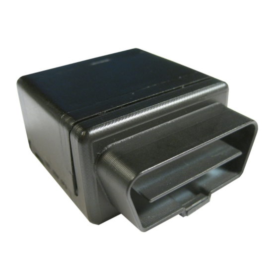
2 Overview 2.1 Description The MT 3000 has a rugged plastic housing that measures 46 x 43 x 28 mm. It contains internal GSM and GPS antennas, internal SIM card holder, J1962 complaint OBDII connector, micro USB connector, and 3 LED indicators. -
Page 16: Barcode Label
Figure: 4 - MT 3000 Label 2.3 Connector & LEDs The MT 3000 includes a J1962 compliant OBDII connector, a micro USB I/O port, and LEDs to indicate OBD II, GSM, and GPS status. The following figure shows the MT 3000 connector and LEDs. -
Page 17: Accelerometer
Mode (Normal, Sleep, Wakeup) Device orientation setup 2.5 GSM Radio The MT 3000 contains a quad-band (850/900/1800/1900 MHz) GSM radio. Class 4 (2W@850/900 MHz) Class 1 (1W@1800/1900 MHz) The MT 3000 has an internal antenna limited to dual band. - 6 -... -
Page 18: Packet Data
2.6 Packet Data Packet data characteristics include: Class B, Multislot 2 GSM/GPRS Rel 97 GSM Functionality includes: Text MO/MT Cell Broadcast 2.7 GPS Functionality GPS functionality includes: NMEA update with all data points Binary Buffered GPS message feature - 7 -... -
Page 19: Hardware Features
3 Hardware Features 3.1 Opening The Device It is highly recommended using the MT 3000 Disassembly Kit (Enfora Part Number KIT2374-01) to remove the cover of the MT 3000. The MT 3000 Disassembly Kit includes the Six-Pin Base and the Metal Lever. -
Page 20: Figure: 7 - Mt 3000
Figure: 7 - MT 3000 2. Gently apply pressure upwards on the lever until the lid unsnaps. Figure: 8 - Lever inserted into MT 3000 lid gap - 9 -... -
Page 21: Figure: 9 - Mt 3000 With Lid Unsnapped
3. Place the MT 3000 into the Base making sure the two small Base Pins are inserted into the two holes in the base of the MT 3000. The four larger pins fit around the outside of the case and help hold the MT 3000 in place during the next step. -
Page 22: Figure: 10 - Mt 3000 On The Opener Base
Figure: 10 - MT 3000 on the Opener Base 4. Apply pressure downwards onto the MT 3000 and slide the MT 3000 Lid backwards away from the rest of the MT 3000. Downward pressure is required while sliding the lid. Exerting the downward pressure releases the internal locking clips. -
Page 23: Figure: 11 - Lid Pulled Away From The Mt 3000
Figure: 11 - Lid pulled away from the MT 3000 Figure: 12 - MT 3000 with Lid completely removed 6. The MT 3000 can now be removed from the Opener Base. - 12 -... -
Page 24: Closing The Device
Figure: 13 - MT 3000 without Lid 3.2 Closing the Device Replace the MT 3000 Lid by using the following steps: 1. Place the MT 3000 Lid onto the base as shown in the following figure. - 13 -... -
Page 25: Sim Card Access
Figure: 14 - Replacing the MT 3000 Lid 2. Carefully slide the lid so that it snaps in place. 3.3 SIM Card Access The top cover of the MT 3000 unsnaps to provide access to the internal SIM holder. - 14 -... -
Page 26: Power
Figure: 15 - Internal SIM Holder 3.4 Power The Enfora MT 3000 device draws 9-16 Vdc (SAE J1211 compliant) power from the vehicle's OBDII port. No additional power cabling is required. 3.5 Micro USB Warning: The Micro USB (2.0) connector is an input/output connector and is not intended for general use. -
Page 27: Figure: 16 - Micro Usb Cable
Figure: 16 - Micro USB Cable - 16 -... -
Page 28: Software Features
GSM0308AN001 - Enabler IIIG AT Commands Over SMS. Store/Transmit Event Data The user can configure the MT 3000 to store event-generated data in its internal memory, to be sent over the air to a remote server. This feature can be enabled or disabled using the AT$MSGLOGEN command. -
Page 29: Excessive Engine Speed (Rpm)
Excessive engine speed alerts are triggered when the engine speed (in RPM) exceed a defined RPM level (in ¼ RPM increments) for a defined period of time in seconds (e.g. 30 seconds). The MT 3000 has three definable thresholds. Unnecessary wear and tear on the powertrain control module (PCM) may occur if constant or frequent excessive engine speed is reported. -
Page 30: Check Engine Light (Mil Alert)
Sets low battery threshold to 10.8volts. If below this threshold for 300 seconds (5 minutes) trigger the input event. restoring voltage abovethe threshold for 300secods (5 minutes) will clear this event. Check Engine Light (MIL Alert) When the vehicle “Check Engine” light illuminates, this indicates a vehicle issue that requires attention for diagnosis and/or repair. -
Page 31: Sudden Deceleration (Harsh Braking)
Sets Rapid accel threshold 1 to .2Gs. If this threshold is exceeded for 1 second, trigger the input event. This event will clear in 30 seconds below this treshold. Sudden Deceleration (Harsh Braking) Rapid deceleration events can be triggered when one of three available vehicle speed thresholds are exceeded as determined by the accelerometer in milli-Gs (e.g. -
Page 32: Installation
5.1 Inserting the SIM Insert the SIM per the following procedure: Note: The SIM card is not provided with the MT 3000 device. The SIM must be obtained from the GSM/GPRS service provider and must be provisioned by the operator for data. Always take care to protect the SIM. Without the SIM installed, MT 3000 modem is not able to communicate on the network. -
Page 33: Device Installation
5.2 Device Installation Instructions provided in this section describe the hardware installation of the MT 3000 device. To install the MT 3000 in a vehicle, follow these steps: Locate the OBDII socket. The location will vary between different vehicle manufacturers, models, and production years. -
Page 34: Accelerometer Calibration
Figure: 18 - Typical OBDII Socket Location Warning: Upon vehicle ignition on, immediately following device installation, the device starts the Accelerometer Auto-calibration process. 5.3 Accelerometer Calibration The accelerometer undergoes an automatic calibration sequence on the first drive after any of the following events: Device installation Software upgrade... -
Page 35: Network Test Procedure
6 Network Test Procedure 6.1 Configuration The Enfora Mobile Tracker family of products is designed with features to support a robust connection with the network. However, there can be conditions when the connection to the network or the ability to transfer data across the network is beyond the control of the device alone. -
Page 36: Figure: 19 - Ati Response
If you do not see the letters AT, send the following command to the device: ii. ATE1<CR> d. Type ATI<CR>. The device should respond with Enfora, Inc. If you get any different response, you are not connected to the Enfora device. See Figure: 19 - "ATI Response"... - Page 37 i. APN ii. Username and password (If necessary.) b. Reset the device to factory defaults: i. To restore the device to factory defaults, send the following command: AT&F<CR> ii. To write current configuration to memory, send the following command: AT&W<CR> iii.
-
Page 38: Figure: 20 - Verify Gprs Status
%CGREG: 0,1 (GPRS registered to home network) %CGREG: 0,5 (GPRS registered roaming.) See Figure: 20 - "Verify GPRS Status" Figure: 20 - Verify GPRS Status Verify GPRS activation by sending the following command: AT$NETIP?<CR> If the response is non-zero, then everything is working. See Figure: 21 - "Verify GPRS Activation"... -
Page 39: Figure: 21 - Verify Gprs Activation
$CGEER: user authentication failed (username and/or password is incorrect.) Configure the device to access the Enfora Server. To configure the device for server interoperability, several things have to be addressed: Most GPRS configurations are Mobile Originate only. The mobile device must initiate a conversation with a remote server before the remote server can talk to the device. - Page 40 Modem ID/name = “MT_Test” Remote Server DNS address = apitest.enfora.com Remote Server IP port = 1721 1. Give the device a unique name send the following command: AT$MDMID=”MT_Test” This command, combined with the wakeup message, will allow the server to associate a Public IP address with a specific device and create a window of opportunity where the server can send commands to the device See Figure: 4 - "Wakeup Command"...
-
Page 41: Verifying Server Connectivity
Note: For the following tests, Java Runtime must be installed on the computer. (To install Java Runtime, please visit the Java website: http://www.java.com/en/download/manual.jsp) 1. Start Internet Explorer and enter the following URL: http://apitest.enfora.com/udpapp/ 2. Enter the name used in the MDMID command in the box. Select Connect See Figure: 23 - "Verify Server Connectivity"... -
Page 42: Figure: 23 - Verify Server Connectivity
Figure: 23 - Verify Server Connectivity 3. Select the tab with the device name. (In this diagram it is labeled "MT_Test") Within approximately 60 seconds the wakeup messages should be seen in the window See Figure: 24 - "Wakeup Mes- sages" - 31 -... -
Page 43: Figure: 24 - Wakeup Messages
4. Enter the following command in the command/ data block: 5. Select Write 6. Verify that you see the device respond with Enfora, Inc. See Figure: 25 - "ATI Response" . If so, you have successfully configured the device to talk with the server. -
Page 44: Verify Gps Operation
2. The device should respond with a standard GPRMC message that looks similar to the following: $GPRMC,221223.00,A,3301.5080,N,09642.3857,W,000.0,000.0,230805,05.9,E,A*19 A = OK V = Warning 9 = Enfora Specific response that GPS solution is not valid and the last known GPS location is being substituted. - 33 -... -
Page 45: Figure: 26 - Verify Gps Operation
Here is an example of a GPRMC message without a GPS lock: $GPRMC,221553.30,V,,,,,,,,,,N*7C The same command can be used in the server application See Figure: 26 - "Verify GPS Operation" . Figure: 26 - Verify GPS Operation - 34 -...
Need help?
Do you have a question about the MT 3000 and is the answer not in the manual?
Questions and answers