Table of Contents
Advertisement
Advertisement
Table of Contents

Related Manuals for Enfora GSM2218


Summary of Contents for Enfora GSM2218
-
Page 1: User Manual
User Manual: GSM2218PB001MAN Enfora MT-GL (GSM/GPRS) User Manual Release 1.03 Confidential and Proprietary Information - © 2005 Enfora, L.P. Do not duplicate without express permission from Enfora, L.P. Enfora L.P. 661 E. 18 Street Plano Texas 75074 www.enfora.com... - Page 2 All specifications are subject to change without notice and do not represent a commitment on the part of Enfora, L.P. Enfora, L.P. will not be responsible for any loss or damages incurred related to the use of information contained in this document.
- Page 3 The modem was tested and certified to meet FCC Parts 15 in a stand-alone configuration, which demonstrated that the GSM2218 MT-GL complies with Part 15 emission limits. FCC Part 22 & Part 24 is covered by the Enfora Enabler-IIG "modular approval" process for a transmitter. This...
-
Page 4: Warranty Information
LIMITED WARRANTY Scope Enfora warrants to the original purchaser of the product that, for a period of one (1) year from the date of product purchase, the product hardware, when used in conjunction with any associated software (including any firmware and applications) supplied by Enfora, will be free from defects in material or workmanship under normal operation. - Page 5 (iii) caused by use of any software other than any software supplied by Enfora, or by use of the product other than in accordance with its documentation or (iv) the result of electrostatic discharge, electrical surge, fire, flood or similar causes.
- Page 6 Date November 11, 2005 1.00 December 7, 2005 1.01 January 4, 2006 1.02 April 7, 2006 1.03 Author Mike Cook Released Added warning in section 2.7 regarding voltage Diane O’Neil Clarified Pin 1 description Diane O’Neil Added CE information Description...
-
Page 7: Table Of Contents
Additional Software Features ... 18 Appendix 1 – Cable Wiring Diagrams... 20 Figure 1 - Enfora MT-GL Front View ... 2 Figure 2 - Enfora MT-GL Back View... 2 Figure 3 - Mounting dimensions of a MT-GL (Shown with mounting plate) ... 4 Figure 4 - MT-GL Mounting Bracket (attached)... -
Page 8: Introduction
(I/O), six selectable National Maritime Electronics Association (NMEA) GPS data format, Trimble ASCII Interface Protocol (TAIP) GPS data format, and Enfora’s own proprietary Binary GPS data format. The MT-GL is designed to work in a stand-alone device in an automobile. Enfora’s MT-GL provides maximum AVL versatility in a single affordable device. -
Page 9: Mt-Gl Front And Back View
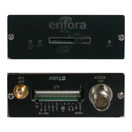
1.6 MT-GL Front and Back View Figure 1 - Enfora MT-GL Front View Figure 2 - Enfora MT-GL Back View GSM2218PB001MAN - GSM/GPRS MT-GL User Manual Page 2 Copyright 2005, Enfora L.P... -
Page 10: Product Specifications
GPS Functionality • SMA Antenna Connector for GPS • Supports 3.3V Active Antenna • GPS Protocols: NMEA, TAIP, Enfora binary • Stored GPS Messages Feature GSM2218PB001MAN - GSM/GPRS MT-GL User Manual Copyright 2005, Enfora L.P Application Interface • Host Protocols:... -
Page 11: Installation
Care must be taken to ensure the device is kept away from water or any other liquids. 2.1 Mounting Dimensions Figure 3 - Mounting dimensions of a MT-GL (Shown with mounting plate) GSM2218PB001MAN - GSM/GPRS MT-GL User Manual Copyright 2005, Enfora L.P Page 4... -
Page 12: Figure 4 - Mt-Gl Mounting Bracket (Attached)
MT-GL. The two pieces will easily slide into the grooves on the modem. Figure 4 - MT-GL Mounting Bracket (attached) GSM2218PB001MAN - GSM/GPRS MT-GL User Manual Page 5 Copyright 2005, Enfora L.P... -
Page 13: Figure 5 - Mt-Gl Mounting Bracket (Separated)
Figure 5 - MT-GL Mounting Bracket (separated) Figure 6 - MT-GL Bracket Installation GSM2218PB001MAN - GSM/GPRS MT-GL User Manual Page 6 Copyright 2005, Enfora L.P... -
Page 14: Installing Cables
All cables should be attached to the vehicle and equipment in such a way to reduce stress or wear caused by vibration generated by moving vehicles. • Use proper terminations on all power cables GSM2218PB001MAN - GSM/GPRS MT-GL User Manual Copyright 2005, Enfora L.P Figure 7 - MT-GL Bracket Installation Page 7... -
Page 15: Pin Connector
2.2.1 12 pin Connector The user can purchase the optional 12-pin external I/O connector for the Enfora MT-GL that can be used to interface with other devices. Enfora can provide an optional cable and connector (Part #ADT2218). The user also has the option of building his/her own cable. Table 1 describes the pin functionality for this 12 pin I/O connector. -
Page 16: Mt-Gl Serial Adapter (Optional)
2.2.2 MT-GL Serial Adapter (Optional) Enfora P/N ADT2218 can be used to provide a standard serial interface for the MT-GL. This adapter provides a standard DB9 serial interface and power to the unit. The adapter would be used for loading new software onto the MT-GL. The customer may choose to connect directly to the 12-pin connector serial interface pins, or order this convenient adapter from Enfora. - Page 17 The customer can also build their own cable, if they choose. The following information contains photographs and the manufacturer’s (AMP/Tyco) part numbers for the parts needed to build the cable. Enfora recommends using 20-gauge wire when building the connector. Pin Housing (2-87499-1)
- Page 18 (out), receive (in) and ground. The following diagram displays the serial end of the interface cable. Pin 1 on the Pin 12 on the MT-GL MT-GL Pin 2 on the MT-GL GSM2218PB001MAN - GSM/GPRS MT-GL User Manual Page 11 Copyright 2005, Enfora L.P...
-
Page 19: Installing Subscriber Identity Module (Sim) Card
SIM card. Failure to do so might result in unusable MT-GL or a damaged SIM card. GSM2218PB001MAN - GSM/GPRS MT-GL User Manual Copyright 2005, Enfora L.P Figure 10 - Inserting a SIM Insert the SIM into the SIM Slot... -
Page 20: Audio In/Audio Out
The only way of connecting the microphone/speaker is via pins 3 - 6 of the 12-pin connector. Please follow the specifications as listed in the table below. Enfora is not liable for damage to the MT-GL caused due to user error. -
Page 21: Connecting Gsm/Gprs Modem Antenna
The antenna connector on the GSM/GPRS MT-GL model is a TNC female connector. The antenna has to be connected to the connector labeled “MODEM ANT”. See Figure 11 - GSM/GPRS Antenna Connection. GSM/GPRS Antenna Figure 11 - GSM/GPRS Antenna Connection GSM2218PB001MAN - GSM/GPRS MT-GL User Manual Page 14 Copyright 2005, Enfora L.P... -
Page 22: Connecting Gps Antenna
The GPS antenna must be connected to the connector labeled “GPS ANT”. See Figure 12 - GPS Antenna Connection. User must disconnect power before connecting the GPS antenna GSM2218PB001MAN - GSM/GPRS MT-GL User Manual Copyright 2005, Enfora L.P Antenna Figure 12 - GPS Antenna Connection Page 15... -
Page 23: Connecting The Power Source
Please follow the specifications as listed in the table below. Enfora is not liable for damage to the MT-GL caused due to user error. Enfora MT-G (@ 12 Volts) GSM 850 &... -
Page 24: Led Operation
By default, this LED indicates GPS fix status. The LED remains in OFF state when invalid GPS data is received. The LED remains ON when valid GPS data is received. GSM2218PB001MAN - GSM/GPRS MT-GL User Manual Copyright 2005, Enfora L.P Page 17... -
Page 25: Additional Software Features
SMS message being treated as a regular SMS message; • Query of an AT command setting that returns more than 160 bytes will result in data being truncated to a maximum of 160 bytes. GSM2218PB001MAN - GSM/GPRS MT-GL User Manual Copyright 2005, Enfora L.P Page 18... - Page 26 12 ASCII character (12-bytes) representing RTC date and time is appended in ASCII format when bit-21 is enabled. Two bytes (or two ASCII characters) represents an individual field GSM2218PB001MAN - GSM/GPRS MT-GL User Manual Copyright 2005, Enfora L.P Page 19...
-
Page 27: Appendix 1 - Cable Wiring Diagrams
Appendix 1 – Cable Wiring Diagrams Figure 13 – Wiring for Power Only Figure 14 – Wire for Programming Cable GSM2218PB001MAN - GSM/GPRS MT-GL User Manual Page 20 Copyright 2005, Enfora L.P...
Need help?
Do you have a question about the GSM2218 and is the answer not in the manual?
Questions and answers
I need to know who has this gps enfora GSM2218-01 Serial number M812T71720866 FCC ID Mivgsm0108 Canada 4160A-GSM0108 i need to get it off my car