Table of Contents
Advertisement
Advertisement
Table of Contents

Related Manuals for Daikin REYQ8-48PY1B


Summary of Contents for Daikin REYQ8-48PY1B
- Page 1 SiENBE37-701 Service Manual REYQ8-48PY1B R-410 Heat Recovery 50HZ...
-
Page 2: Table Of Contents
SiENBE37-701 R-410A Heat Recovery 50Hz 1. Introduction .................... vi 1.1 Safety Cautions ..................vi 1.2 PREFACE ....................x Part 1 General Information ............1 1. Model Names of Indoor/Outdoor Units............2 2. External Appearance................3 2.1 Indoor Units ....................3 2.2 Outdoor Units ...................4 3. - Page 3 SiENBE37-701 2.3 Electronic Expansion Valve PI Control..........114 2.4 Step Control of Outdoor Unit Fans ............114 2.5 Outdoor Unit Fan Control in Cooling Operation ........115 2.6 Heat Exchanger Control ...............116 3. Special Control..................117 3.1 Startup Control ..................117 3.2 Large Capacity Start Up Control (Heating)...........119 3.3 Oil Return Operation ................120 3.4 Defrost Operation .................124 3.5 Pump-down Residual Operation ............126...
- Page 4 SiENBE37-701 2.5 Remote Control Service Mode .............241 2.6 Test Run Mode..................243 2.7 Remote Control Self-Diagnosis Function ..........243 3. Troubleshooting by Indication on the Remote Control ......250 3.1 “A0” Indoor Unit: Error of External Protection Device ......250 3.2 “A1” Indoor Unit: PC Board Defect............251 3.3 “A3”...
- Page 5 SiENBE37-701 3.38 “L5” Outdoor Unit: Momentary Overcurrent of Inverter Compressor..308 3.39 “L8” Outdoor Unit: Momentary Overcurrent of Inverter Compressor..310 3.40 “L9” Outdoor Unit: Inverter Compressor Starting Failure ......312 3.41 “LC” Outdoor Unit: Malfunction of Transmission between Inverter and Con- trol PC Board315 3.42 “P1”...
- Page 6 SiENBE37-701 3. List of Electrical and Functional Parts ..........418 3.1 Outdoor Unit ..................418 3.2 Indoor Side ...................422 4. Option List ...................428 4.1 Option List of Controllers..............428 4.2 Option Lists (Outdoor Unit)..............430 5. Piping Installation Point...............431 5.1 Piping Installation Point ................431 5.2 The Example of a Wrong Pattern ............432 6.
-
Page 7: Introduction
SiENBE37-701 Introduction 1. Introduction Safety Cautions Cautions and ! Be sure to read the following safety cautions before conducting repair work. Warnings ! The caution items are classified into “ Warning” and “ Caution”. The “ Warning” items are especially important since they can lead to death or serious injury if they are not followed closely. - Page 8 Introduction SiENBE37-701 Caution Do not repair the electrical components with wet hands. Working on the equipment with wet hands can cause an electrical shock. Do not clean the air conditioner by splashing water. Washing the unit with water can cause an electrical shock. Be sure to provide the grounding when repairing the equipment in a humid or wet place, to avoid electrical shocks.
- Page 9 SiENBE37-701 Introduction Warning Be sure to use the specified cable to connect between the indoor and outdoor units. Make the connections securely and route the cable properly so that there is no force pulling the cable at the connection terminals. Improper connections can cause excessive heat generation or fire.
- Page 10 Introduction SiENBE37-701 Caution Check to see if the parts and wires are mounted and connected properly, and if the connections at the soldered or crimped terminals are secure. Improper installation and connections can cause excessive heat generation, fire or an electrical shock. If the installation platform or frame has corroded, replace it.
-
Page 11: Preface
This is the new service manual for Daikin's Year 2007 VRVIII series Heat Recovery System. Daikin offers a wide range of models to respond to building and office air conditioning needs. We are confident that customers will be able to find the models that best suit their needs. - Page 12 Introduction SiENBE37-701...
-
Page 13: Part 1 General Information
SiENBE37-701 Part 1 General Information 1. Model Names of Indoor/Outdoor Units............2 2. External Appearance................3 2.1 Indoor Units ....................3 2.2 Outdoor Units ...................4 3. Combination of Outdoor Units..............5 4. Model Selection..................6 General Information... -
Page 14: Model Names Of Indoor/Outdoor Units
Model Names of Indoor/Outdoor Units SiENBE37-701 1. Model Names of Indoor/Outdoor Units Indoor Units Power Type Model Name Supply Roundflow Ceiling FXFQ 100P 125P — — Mounted Cassette 600×600 4-Way Blow FXZQ — — — — — — Ceiling Mounted Cassette 2-Way Blow Ceiling FXCQ... -
Page 15: External Appearance
SiENBE37-701 External Appearance 2. External Appearance Indoor Units Roundflow Ceiling Mounted Cassette Concealed Ceiling Unit (Large) FXFQ20P FXMQ40MA FXFQ25P FXMQ50MA FXFQ32P FXMQ63MA FXMQ40~125M FXFQ40P FXMQ80MA FXFQ50P FXMQ100MA FXFQ63P FXMQ125MA FXFQ80P FXMQ200MA FXFQ100P FXMQ250MA FXMQ200 · 250M FXFQ125P 600×600 4-Way Blow Ceiling Suspended Unit Ceiling Mounted Cassette FXHQ32MA... -
Page 16: Outdoor Units
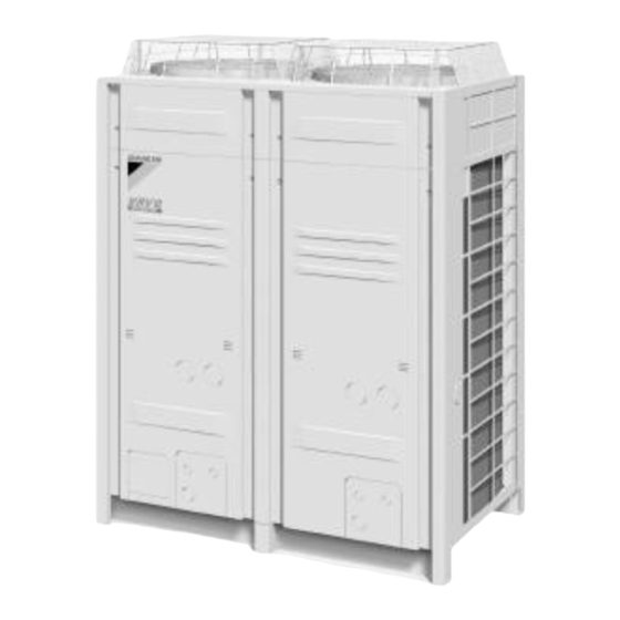
External Appearance SiENBE37-701 Outdoor Units REYQ8P, 10P, 12P, 14P, 16P REYQ18P, 20P, 22P, 24P 8, 10, 12, 14, 16 HP 18, 20, 22, 24 HP 22.4 ~ 40.0, 45.0 kW 50.4 ~ 67.0 kW REYQ26P, 28P REYQ30P, 32P REYQ34P, 36P, 38P, 40P 26, 28 HP 30, 32 HP 34, 36, 38, 40 HP... -
Page 17: Combination Of Outdoor Units
Heat Recovery: BHFP26P90 26HP 28HP 30HP 32HP 34HP 36HP 38HP 40HP Heat Recovery: BHFP26P136 42HP 44HP 46HP 48HP Note: For multiple connection of 18HP system or more, an optional Daikin Outdoor Unit Multi Connection Piping Kit is required. General Information... -
Page 18: Model Selection
Model Selection SiENBE37-701 4. Model Selection VRV III Heat Recovery Series Connectable indoor units number and capacity Normal Series 10HP 12HP 14HP 16HP 18HP 20HP System name REYQ8P REYQ10P REYQ12P REYQ14P REYQ16P REYQ18P REYQ20P Outdoor unit 1 REYQ8P REYQ10P REYQ12P REYQ14P REYQ16P REMQ8P... - Page 19 SiENBE37-701 Model Selection Connectable Indoor Unit Power Type Model Name Supply Roundflow Ceiling FXFQ 100P 125P — — Mounted Cassette 600×600 4-Way Blow FXZQ — — — — — — Ceiling Mounted Cassette 2-Way Blow Ceiling FXCQ — 125M — —...
- Page 20 Model Selection SiENBE37-701 Differences from Conventional Models Differences Item Object New model (P Model) Conventional model (M Model) " NONE Compressor Connection of equalizer oil pipe (No particular changes in " YES terms of service) Equalizer oil pipe for multi- "...
- Page 21 SiENBE37-701 Part 2 Specifications 1. Specifications ..................10 1.1 Outdoor Units ..................10 1.2 Indoor Units ....................21 1.3 BS Units ....................54 Specifications...
-
Page 22: Part 2 Specifications
Specifications SiENBE37-701 1. Specifications Outdoor Units Heat Recovery 50Hz <REYQ-P> Model Name REYQ8PY1B REYQ10PY1B kcal / h 19,400 24,300 H1 Cooling Capacity (19.5°CWB) Btu / h 76,800 96,200 22.5 28.2 H2 Cooling Capacity (19.0°CWB) 22.4 28.0 kcal / h 21,500 27,100 H3 Heating Capacity Btu / h... - Page 23 SiENBE37-701 Specifications Model Name REYQ12PY1B REYQ14PY1B kcal / h 29,000 35,500 H1 Cooling Capacity (19.5°CWB) Btu / h 115,000 141,000 33.7 41.3 H2 Cooling Capacity (19.0°CWB) 33.5 40.0 kcal / h 32,300 38,700 H3 Heating Capacity Btu / h 128,000 154,000 37.5 45.0...
- Page 24 Specifications SiENBE37-701 Model Name REYQ16PY1B kcal / h 40,000 H1 Cooling Capacity (19.5°CWB) Btu / h 159,000 46.5 H2 Cooling Capacity (19.0°CWB) 45.0 kcal / h 43,000 H3 Heating Capacity Btu / h 171,000 50.0 Y1 Type Ivory White 5Y7.5/1 Casing Color Y1E Type Light Camel 2.5Y6.5/1.5...
- Page 25 SiENBE37-701 Specifications Model Name (Combination Unit) REYQ18P7Y1B REYQ20P7Y1B Model Name (Independent Unit) REMQ8P7Y1B+REMQ10P7Y1B REMQ8P7Y1B+REMQ12P7Y1B kcal / h 43,600 48,300 H1 Cooling Capacity (19.5°CWB) Btu / h 173,000 192,000 50.7 56.2 H2 Cooling Capacity (19.0°CWB) 50.4 55.9 kcal / h 48,600 53,800 H3 Heating Capacity Btu / h...
- Page 26 Specifications SiENBE37-701 Model Name (Combination Unit) REYQ22P7Y1B REYQ24P7Y1B Model Name (Independent Unit) REMQ10P7Y1B+REMQ12P7Y1B REMQ12P7Y1B+REMQ12P7Y1B kcal / h 53,200 58,000 H1 Cooling Capacity (19.5°CWB) Btu / h 211,000 230,000 61.9 67.4 H2 Cooling Capacity (19.0°CWB) 61.5 67.0 kcal / h 59,300 64,500 H3 Heating Capacity Btu / h...
- Page 27 SiENBE37-701 Specifications Model Name (Combination Unit) REYQ26P7Y1B REYQ28P7Y1B Model Name (Independent Unit) REMQ10P7Y1B+REMQ16P7Y1B REMQ12P7Y1B+REMQ16P7Y1B kcal / h 63,100 67,900 H1 Cooling Capacity (19.5°CWB) Btu / h 250,000 270,000 73.4 79.0 H2 Cooling Capacity (19.0°CWB) 73.0 78.5 kcal / h 70,100 75,300 H3 Heating Capacity Btu / h...
- Page 28 Specifications SiENBE37-701 Model Name (Combination Unit) REYQ30P7Y1B REYQ32P7Y1B Model Name (Independent Unit) REMQ14P7Y1B+REMQ16P7Y1B REMQ16P7Y1B+REMQ16P7Y1B kcal / h 73,500 77,800 H1 Cooling Capacity (19.5°CWB) Btu / h 292,000 309,000 85.5 90.5 H2 Cooling Capacity (19.0°CWB) 85.0 90.0 kcal / h 81,700 86,000 H3 Heating Capacity Btu / h...
- Page 29 SiENBE37-701 Specifications Model Name (Combination Unit) REYQ34P7Y1B REYQ36P7Y1B Model Name (Independent Unit) REMQ8P7Y1B+REMQ10P7Y1B+REMQ16P7Y1B REMQ8P7Y1B+REMQ12P7Y1B+REMQ16P7Y1B kcal / h 82,600 87,700 H1 Cooling Capacity (19.5°CWB) Btu / h 328,000 348,000 96.0 H2 Cooling Capacity (19.0°CWB) 95.4 kcal / h 92,000 97,200 H3 Heating Capacity Btu / h 365,000 386,000...
- Page 30 Specifications SiENBE37-701 Model Name (Combination Unit) REYQ38P7Y1B REYQ40P7Y1B Model Name (Independent Unit) REMQ10P7Y1B+REMQ12P7Y1B+REMQ16P7Y1B REMQ12P7Y1B+REMQ12P7Y1B+REMQ16P7Y1B kcal / h 92,900 97,200 H1 Cooling Capacity (19.5°CWB) Btu / h 368,000 386,000 H2 Cooling Capacity (19.0°CWB) kcal / h 102,000 108,000 H3 Heating Capacity Btu / h 406,000 427,000...
- Page 31 SiENBE37-701 Specifications Model Name (Combination Unit) REYQ42P7Y1B REYQ44P7Y1B Model Name (Independent Unit) REMQ10P7Y1B+REMQ16P7Y1B+REMQ16P7Y1B REMQ12P7Y1B+REMQ16P7Y1B+REMQ16P7Y1B kcal / h 102,000 108,000 H1 Cooling Capacity (19.5°CWB) Btu / h 406,000 427,000 H2 Cooling Capacity (19.0°CWB) kcal / h 114,000 119,000 H3 Heating Capacity Btu / h 450,000 471,000...
- Page 32 Specifications SiENBE37-701 Model Name (Combination Unit) REYQ46P7Y1B REYQ48P7Y1B Model Name (Independent Unit) REMQ14P7Y1B+REMQ16P7Y1B+REMQ16P7Y1B REMQ16P7Y1B+REMQ16P7Y1B+REMQ16P7Y1B kcal / h 113,000 117,000 H1 Cooling Capacity (19.5°CWB) Btu / h 447,000 464,000 H2 Cooling Capacity (19.0°CWB) kcal / h 124,000 129,000 H3 Heating Capacity Btu / h 495,000 512,000...
-
Page 33: Indoor Units
SiENBE37-701 Specifications Indoor Units Roundflow Ceiling Mounted Cassette 1-1 TECHNICAL SPECIFICATIONS FXFQ20PVEB FXFQ25PVEB FXFQ32PVEB FXFQ40PVEB FXFQ50PVEB Capacity Cooling Heating Power Input Cooling 0.053 0.053 0.053 0.063 0.083 Heating 0.045 0.045 0.045 0.055 0.067 Casing Material Galvanised steel Dimensions Packing Height Width Depth Unit... - Page 34 Specifications SiENBE37-701 Roundflow Ceiling Mounted Cassette 1-1 TECHNICAL SPECIFICATIONS FXFQ20PVEB FXFQ25PVEB FXFQ32PVEB FXFQ40PVEB FXFQ50PVEB Standard Standard Accessories Installation and operation manual Accessories Drain hose Washer for hanging bracket Screws Sealing Pads Insulation for fitting Clamp for drain hose Installation guide Drain sealing pad Notes The sound pressure values are mentioned for a unit installed with rear suction...
- Page 35 SiENBE37-701 Specifications Roundflow Ceiling Mounted Cassette 1-1 TECHNICAL SPECIFICATIONS FXFQ63PVEB FXFQ80PVEB FXFQ100PVEB FXFQ125PVEB Piping Liquid Type Flare connection connections (OD) Diameter Type Flare connection Diameter 15.9 15.9 15.9 15.9 Drain Diameter VP25 (I.D. 25/O.D. 32) Heat Insulation Foamed polystyrene/polyethylene Sound absorbing insulation (Foamed Polyurethane) Decoration Model...
- Page 36 Specifications SiENBE37-701 1-2 ELECTRICAL SPECIFICATIONS FXFQ20PVEB FXFQ25PVEB FXFQ32PVEB FXFQ40PVEB FXFQ50PVEB Power Name Supply Frequency 50/60 Voltage 220-240/220 Current Minimum circuit amps (MCA) Maximum fuse amps (MFA) Full load amps (FLA) Voltage Minimum -10% range Maximum +10% Notes Voltage range : units are suitable for use on electrical systems where voltage supplied to unit terminals is not below or above listed range limits.
- Page 37 SiENBE37-701 Specifications 600×600 4-Way Blow Ceiling Mounted Cassette 1-1 TECHNICAL SPECIFICATIONS FXZQ20MV1B FXZQ25MV1B FXZQ32MV1B FXZQ40MV1B FXZQ50MV1B Nominal Cooling 2.20 2.80 3.60 4.50 5.60 Capacity Heating 2.50 3.20 4.00 5.00 6.30 Power input Cooling 0.073 0.073 0.076 0.089 0.115 (Nominal) Heating 0.064 0.064 0.068...
- Page 38 Specifications SiENBE37-701 1-1 TECHNICAL SPECIFICATIONS FXZQ20MV1B FXZQ25MV1B FXZQ32MV1B FXZQ40MV1B FXZQ50MV1B Notes Nominal cooling capacities are based on : indoor temperature : 27°CDB, 19°CWB, outdoor temperature : 35°CDB, equivalent refrigerant piping : 7.5m (horizontal) Nominal heating capacities are based on : indoor temperature : 20°CDB, outdoor temperature : 7°CDB, 6°CWB, equivalent refrigerant piping : 7.5m (horizontal) Capacities are net, including a deduction for cooling (an addition for heating) for indoor fan motor heat.
- Page 39 SiENBE37-701 Specifications 2-Way Blow Ceiling Mounted Cassette 1-1 TECHNICAL SPECIFICATIONS FXCQ20MV3B FXCQ25MV3B FXCQ32MV3B FXCQ40MV3B FXCQ50MV3B Nominal Cooling 2.20 2.80 3.60 4.50 5.60 Capacity Heating 2.50 3.20 4.00 5.00 6.30 Power input Cooling 0.077 0.092 0.092 0.130 0.130 (Nominal) Heating 0.044 0.059 0.059 0.097...
- Page 40 Specifications SiENBE37-701 2-Way Blow Ceiling Mounted Cassette 1-1 TECHNICAL SPECIFICATIONS FXCQ20MV3B FXCQ25MV3B FXCQ32MV3B FXCQ40MV3B FXCQ50MV3B Air Filter Resin net with mold resistance Air direction control Up and downwards Refrigerant control Electronic expansion valve Temperature control Microprocessor thermostat for cooling and heating Safety devices PC board fuse Fan motor thermal fuse...
- Page 41 SiENBE37-701 Specifications 1-1 TECHNICAL SPECIFICATIONS FXCQ63MV3B FXCQ80MV3B FXCQ125MV3B Nominal Cooling 7.10 9.00 14.00 Capacity Heating 8.00 10.00 16.00 Power input Cooling 0.161 0.209 0.256 (Nominal) Heating 0.126 0.176 0.223 Casing Colour Non painted Material Galvanised steel Dimensions Packing Height Width 1,460 1,808 1,808...
- Page 42 Specifications SiENBE37-701 1-1 TECHNICAL SPECIFICATIONS FXCQ63MV3B FXCQ80MV3B FXCQ125MV3B Air Filter Resin net with mold resistance Air direction control Up and downwards Refrigerant control Electronic expansion valve Temperature control Microprocessor thermostat for cooling and heating Safety devices PC board fuse Fan motor thermal fuse Fan motor thermal protector Fan motor thermal protector Drain pump fuse...
- Page 43 SiENBE37-701 Specifications 1-2 ELECTRICAL SPECIFICATIONS FXCQ20MV3B FXCQ25MV3B FXCQ32MV3B FXCQ40MV3B FXCQ50MV3B Power Name Supply Phase Frequency Voltage Current Minimum circuit amps 0.50 0.50 0.50 0.80 0.80 (MCA) Maximum fuse amps 16.00 16.00 16.00 16.00 16.00 (MFA) Full load amps (FLA) 0.40 0.40 0.40 0.60...
- Page 44 Specifications SiENBE37-701 Ceiling Mounted Corner Cassette 1-1 TECHNICAL SPECIFICATIONS FXKQ25MAVE FXKQ32MAVE FXKQ40MAVE FXKQ63MAVE Nominal Cooling 2.80 3.60 4.50 7.10 Capacity Heating 3.20 4.00 5.00 8.00 Power input Cooling 0.066 0.066 0.076 0.105 (Nominal) Heating 0.046 0.046 0.056 0.085 Casing Material Galvanised steel Dimensions Unit...
- Page 45 SiENBE37-701 Specifications 1-1 TECHNICAL SPECIFICATIONS FXKQ25MAVE FXKQ32MAVE FXKQ40MAVE FXKQ63MAVE Notes Nominal cooling capacities are based on : indoor temperature : 27°CDB, 19°CWB, outdoor temperature : 35°CDB, equivalent refrigerant piping : 7.5m (horizontal) Nominal heating capacities are based on: indoor temperature : 20°CDB, outdoor temperature : 7°CDB, 6°CWB, equivalent refrigerant piping : 7.5m (horizontal) Capacities are net, including a deduction for cooling (an addition for heating) for indoor fan motor heat.
- Page 46 Specifications SiENBE37-701 Slim Concealed Ceiling Unit (with Drain Pump) 1-1 TECHNICAL SPECIFICATIONS FXDQ20PVE FXDQ25PVE FXDQ32PVE FXDQ40NAVE FXDQ50NAVE FXDQ63NAVE Nominal Cooling 2.20 2.80 3.60 4.50 5.60 7.10 Capacity Heating 2.50 3.20 4.00 5.00 6.30 8.00 Power input Cooling 0.086 0.086 0.089 0.160 0.165 0.181...
- Page 47 SiENBE37-701 Specifications Slim Concealed Ceiling Unit (with Drain Pump) 1-2 ELECTRICAL SPECIFICATIONS FXDQ20PVE FXDQ25PVE FXDQ32PVE FXDQ40NAVE FXDQ50NAVE FXDQ63NAVE Power Name Supply Phase Frequency Voltage 220-240 Current Minimum circuit amps 0.80 0.80 0.80 1.00 1.00 1.10 (MCA) Maximum fuse amps 15.00 15.00 15.00 15.00...
- Page 48 Specifications SiENBE37-701 Concealed Ceiling Unit (Small) 1-1 TECHNICAL SPECIFICATIONS FXDQ20MV3B FXDQ25MV3B Nominal Cooling 2.20 2.80 Capacity Heating 2.50 3.20 Power input Cooling 0.050 0.050 (Nominal) Heating 0.050 0.050 Casing Colour Non painted Material Galvanised steel Dimensions Packing Height Width Depth Unit Height Width...
- Page 49 SiENBE37-701 Specifications 1-1 TECHNICAL SPECIFICATIONS FXDQ20MV3B FXDQ25MV3B Standard Standard Accessories Installation and operation manual Accessories Fuse Caution for servicing sticker Suction air filter Notes Nominal cooling capacities are based on : indoor temperature : 27°CDB, 19°CWB, outdoor temperature : 35°CDB, equivalent refrigerant piping : 8m, level difference : 0m.
- Page 50 Specifications SiENBE37-701 Concealed Ceiling Unit 1-1 TECHNICAL SPECIFICATIONS FXSQ20MV3B FXSQ25MV3B FXSQ32MV3B FXSQ40MV3B FXSQ50MV3B Capacity Cooling 2.20 2.80 3.60 4.50 5.60 (Conditions Heating 2.50 3.20 4.00 5.00 6.30 specified in 1) Power input Cooling 0.110 0.110 0.114 0.127 0.143 (Nominal) Heating 0.090 0.090 0.094...
- Page 51 SiENBE37-701 Specifications Concealed Ceiling Unit 1-1 TECHNICAL SPECIFICATIONS FXSQ20MV3B FXSQ25MV3B FXSQ32MV3B FXSQ40MV3B FXSQ50MV3B Decoration Model BYBS32DJW1 BYBS32DJW1 BYBS32DJW1 BYBS45DJW1 BYBS45DJW1 Panel Colour White (10Y9/0,5) Dimensions Height Width Depth Weight Drain-up Height Air Filter Resin net with mold resistance Air direction control Up and downwards Refrigerant control Electronic expansion valve...
- Page 52 Specifications SiENBE37-701 Concealed Ceiling Unit 1-1 TECHNICAL SPECIFICATIONS FXSQ63MV3B FXSQ80MV3B FXSQ100MV3B FXSQ125MV3B Capacity Cooling 7.10 9.00 11.20 14.00 (Conditions Heating 8.00 10.00 12.50 16.00 specified in Power input Cooling 0.189 0.234 0.242 0.321 (Nominal) Heating 0.169 0.214 0.222 0.301 Casing Colour Non painted Material...
- Page 53 SiENBE37-701 Specifications 1-1 TECHNICAL SPECIFICATIONS FXSQ63MV3B FXSQ80MV3B FXSQ100MV3B FXSQ125MV3B Decoration Model BYBS71DJW1 BYBS125DJW1 BYBS125DJW1 BYBS125DJW1 Panel Colour White (10Y9/0,5) Dimensions Height Width 1,100 1,500 1,500 1,500 Depth Weight Drain-up Height Air Filter Resin net with mold resistance Air direction control Up and downwards Refrigerant control Electronic expansion valve...
- Page 54 Specifications SiENBE37-701 1-2 ELECTRICAL SPECIFICATIONS FXSQ20MV3B FXSQ25MV3B FXSQ32MV3B FXSQ40MV3B FXSQ50MV3B Power Name Supply Phase Frequency Voltage Current Minimum circuit amps 0.50 0.50 0.50 0.60 0.90 (MCA) Maximum fuse amps 16.00 16.00 16.00 16.00 16.00 (MFA) Full load amps (FLA) 0.40 0.40 0.40 0.50...
- Page 55 SiENBE37-701 Specifications Concealed Ceiling Unit (Large) 1-1 TECHNICAL SPECIFICATIONS FXMQ40MAVE FXMQ50MAVE FXMQ63MAVE FXMQ80MAVE Nominal Cooing 4.50 5.60 7.10 9.00 Capacitry Heating 5.00 6.30 8.00 10.00 Power input Cooing 0.211 0.211 0.211 0.284 (Nominal) Heating 0.211 0.211 0.211 0.284 Casing Material Galvanised steel Dimensions Unit...
- Page 56 Specifications SiENBE37-701 Concealed Ceiling Unit (Large) 1-1 TECHNICAL SPECIFICATIONS FXMQ100MAVE FXMQ125MAVE FXMQ200MAVE FXMQ250MAVE Nominal Cooling 11.20 14.00 22.40 28.00 Capacity Heating 12.50 16.00 25.00 31.50 Power input Cooling 0.411 0.619 1.294 1.465 (Nominal) Heating 0.411 0.619 1.294 1.465 Casing Material Galvanised steel Dimensions Unit...
- Page 57 SiENBE37-701 Specifications 1-2 ELECTRICAL SPECIFICATIONS FXMQ40MAVE FXMQ50MAVE FXMQ63MAVE FXMQ80MAVE Power Name Supply Phase Frequency Voltage 220-240 Current Minimum circuit amps 1.30 1.30 1.30 1.50 (MCA) Maximum fuse amps 15.00 15.00 15.00 15.00 (MFA) Full load amps (FLA) 1.00 1.00 1.00 1.20 Voltage Minimum...
- Page 58 Specifications SiENBE37-701 Ceiling Suspended Unit 1-1 TECHNICAL SPECIFICATIONS FXHQ32MAVE FXHQ63MAVE FXHQ100MAVE Nominal Cooling 3.60 7.10 11.20 Capacity Heating 4.00 8.00 12.50 Power input Cooling 0.111 0.115 0.135 (Nominal) Heating 0.111 0.115 0.135 Casing Colour White (10Y9/0.5) Dimensions Unit Height Width 1,160 1,400 Depth...
- Page 59 SiENBE37-701 Specifications 1-2 ELECTRICAL SPECIFICATIONS FXHQ32MAVE FXHQ63MAVE FXHQ100MAVE Power Name Supply Phase Frequency Voltage 220-240 Current Minimum circuit amps 0.80 0.80 0.90 (MCA) Maximum fuse amps 15.00 15.00 15.00 (MFA) Full load amps (FLA) 0.60 0.60 0.70 Voltage Minimum -10% range Maximum +10%...
- Page 60 Specifications SiENBE37-701 Wall Mounted Unit 1-1 TECHNICAL SPECIFICATIONS FXAQ20MAVE FXAQ25MAVE FXAQ32MAVE FXAQ40MAVE FXAQ50MAVE FXAQ63MAVE Nominal Cooling 2.20 2.80 3.60 4.50 5.60 7.10 Capacity Heating 2.50 3.20 4.00 5.00 6.30 8.00 Power input Cooling 0.016 0.022 0.027 0.020 0.027 0.050 (Nominal) Heating 0.024 0.027...
- Page 61 SiENBE37-701 Specifications Wall Mounted Unit 1-2 ELECTRICAL SPECIFICATIONS FXAQ20MAVE FXAQ25MAVE FXAQ32MAVE FXAQ40MAVE FXAQ50MAVE FXAQ63MAVE Power Name Supply Phase Frequency Voltage 220-240 Current Minimum circuit amps 0.30 0.40 0.40 0.40 0.40 0.60 (MCA) Maximum fuse amps 15.00 15.00 15.00 15.00 15.00 15.00 (MFA) Full load amps (FLA)
- Page 62 Specifications SiENBE37-701 Floor Standing Unit 1-1 TECHNICAL SPECIFICATIONS FXLQ20MAVE FXLQ25MAVE FXLQ32MAVE FXLQ40MAVE FXLQ50MAVE FXLQ63MAVE Nominal Cooling 2.20 2.80 3.60 4.50 5.60 7.10 Capacity Heating 2.50 3.20 4.00 5.00 6.30 8.00 Power input Cooling 0.049 0.049 0.090 0.090 0.110 0.110 (Nominal) Heating 0.049 0.049...
- Page 63 SiENBE37-701 Specifications Floor Standing Unit 1-2 ELECTRICAL SPECIFICATIONS FXLQ20MAVE FXLQ25MAVE FXLQ32MAVE FXLQ40MAVE FXLQ50MAVE FXLQ63MAVE Power Name Supply Phase Frequency Voltage 220-240 Current Minimum circuit amps 0.30 0.30 0.60 0.60 0.60 0.60 (MCA) Maximum fuse amps 15.00 15.00 15.00 15.00 15.00 15.00 (MFA) Full load amps (FLA)
- Page 64 Specifications SiENBE37-701 Concealed Floor Standing Unit 1-1 TECHNICAL SPECIFICATIONS FXNQ20MAVE FXNQ25MAVE FXNQ32MAVE FXNQ40MAVE FXNQ50MAVE FXNQ63MAVE Nominal Cooling 2.20 2.80 3.60 4.50 5.60 7.10 Capacity Heating 2.50 3.20 4.00 5.00 6.30 8.00 Power input Cooling 0.049 0.049 0.090 0.090 0.110 0.110 (Nominal) Heating 0.049...
- Page 65 SiENBE37-701 Specifications Concealed Floor Standing Unit 1-2 ELECTRICAL SPECIFICATIONS FXNQ20MAVE FXNQ25MAVE FXNQ32MAVE FXNQ40MAVE FXNQ50MAVE FXNQ63MAVE Power Name Supply Phase Frequency Voltage 220-240 Current Minimum circuit amps 0.30 0.30 0.60 0.60 0.60 0.60 (MCA) Maximum fuse amps 15.00 15.00 15.00 15.00 15.00 15.00 (MFA)
-
Page 66: Bs Units
Specifications SiENBE37-701 BS Units Model BSVQ100PV1 BSVQ160PV1 BSVQ250PV1 Power Supply 1 Phase 50Hz 200-240V 1 Phase 50Hz 200-240V 1 Phase 50Hz 200-240V Total Capacity Index of Indoor Unit 20 to 100 More than 100 but 160 or less More than 160 but 250 or less No. -
Page 67: Part 3 Refrigerant Circuit
SiENBE37-701 Part 3 Refrigerant Circuit 1. Refrigerant Circuit .................56 1.1 REYQ8P, 10P, 12P ................56 1.2 REYQ14P, 16P ..................58 1.3 REMQ8P (Multi 8HP) ................60 1.4 REMQ10P, 12P (Multi 10, 12HP)............62 1.5 REMQ14P, 16P (Multi 14, 16HP)............64 1.6 BS Unit Functional Parts ................66 1.7 Indoor Units ....................67 2. -
Page 68: Refrigerant Circuit
Refrigerant Circuit SiENBE37-701 1. Refrigerant Circuit REYQ8P, 10P, 12P No. in refrigerant Symbol Name Major Function system diagram Inverter compressor (INV) Inverter compressor is operated on frequencies between 52Hz and 210Hz by using the inverter, while Standard compressor is operated with commercial power supply only. -
Page 69: Sienbe37
SiENBE37-701 Refrigerant Circuit REYQ8P, 10P, 12P (8HP, 10HP, 12HP Single Type) (INV Unit + STD Unit) Liquid Subcool Heat Exchanger 2 Pipe Left Stop Valve Heat Exchanger 2 Dual Pressure Gas Pipe Stop Valve S2PH Suction Pipe Stop Valve Subcool Heat Exchanger 1 Right Heat Exchanger 1 Gauge Port... -
Page 70: Reyq14P, 16P
Refrigerant Circuit SiENBE37-701 REYQ14P, 16P No. in refrigerant Symbol Name Major Function system diagram Inverter compressor (INV1) Inverter compressor is operated on frequencies between 52Hz and 266Hz by using the inverter. The number of operating steps is as follows. REYQ14P or 16P : 26 step Standard compressor 1 (INV2) Since the system is of air heat exchanging type, the fan is operated at 9-step rotation Inverter fan... - Page 71 SiENBE37-701 Refrigerant Circuit REYQ14P, 16P (14HP, 16HP Single Type) (INV Unit × 2) Liquid Subcool Heat Exchanger 2 Pipe Left Stop Valve Heat Exchanger 2 Dual Pressure Gas Pipe Stop Valve S2PH INV2 Suction Pipe Stop Valve Subcool Heat Exchanger 1 Right Liquid Pipe Heat Exchanger 1...
-
Page 72: Remq8Py1 (Multi 8Hp)
Refrigerant Circuit SiENBE37-701 REMQ8PY1 (Multi 8HP) No. in refrigerant Symbol Name Major Function system diagram Inverter compressor is operated on frequencies between 52Hz and 210Hz by using Inverter compressor (INV) the inverter. Compressor operation steps : Refer to page 110~113. Since the system is of air heat exchanging type, the fan is operated at 9-step rotation Inverter fan speed by using the inverter. - Page 73 SiENBE37-701 Refrigerant Circuit REMQ8PY1 Stop Valve Liquid Pipe S1NPH Stop Valve Equalizing Pipe Stop Valve Dual Pressure Gas Pipe S1PH S2NPL Gauge Port Stop Valve Suction Pipe Refrigerant Circuit...
-
Page 74: Remq10Py1, 12Py1 (Multi 10, 12Hp)
Refrigerant Circuit SiENBE37-701 REMQ10PY1, 12PY1 (Multi 10, 12HP) No. in refrigerant Symbol Name Major Function system diagram Inverter compressor (INV) Inverter compressor is operated on frequencies between 52Hz and 210Hz by using the inverter, while Standard compressor is operated with commercial power supply only. - Page 75 SiENBE37-701 Refrigerant Circuit REMQ10PY1, 12PY1 Stop Valve Liquid Pipe S1NPH Stop Valve Equalizing Pipe Stop Valve Dual Pressure Gas Pipe S1PH S2PH S2NPL Gauge Port Stop Valve Suction Pipe Refrigerant Circuit...
-
Page 76: Remq14Py1, 16Py1 (Multi 14, 16Hp)
Refrigerant Circuit SiENBE37-701 REMQ14PY1, 16PY1 (Multi 14, 16HP) No. in refrigerant Symbol Name Major Function system diagram Inverter compressor (INV) Inverter compressor is operated on frequencies between 52Hz and 210Hz by using the inverter, while Standard compressor is operated with commercial power supply only. The number of Standard compressor 1 (STD1) operating steps is as follows when Inverter compressor is operated in combination with Standard compressor. - Page 77 SiENBE37-701 Refrigerant Circuit REMQ14PY1, 16PY1 Stop Valve Liquid Pipe S1NPH Stop Valve Equalizing Pipe Stop Valve Dual Pressure Gas Pipe S1PH S2PH S3PH S2NPL Gauge Port Stop Valve Suction Pipe Refrigerant Circuit...
-
Page 78: Bs Unit Functional Parts
Refrigerant Circuit SiENBE37-701 BS Unit Functional Parts BSVQ100,160,250PV1 Name Symbol Function Electronic expansion valve (EVH) Opens while in heating operation or all indoor units are in cooling operation. (Max : 760pls) Electronic expansion valve (EVL) Opens while in cooling operation. (Max : 760pls) Electronic expansion valve (EVHS) Opens while in heating operation or all indoor units are in cooling operation. -
Page 79: Indoor Units
SiENBE37-701 Refrigerant Circuit Indoor Units FXCQ, FXFQ, FXZQ, FXKQ, FXDQ, FXDYQ, FXSQ, FXMQ, FXHQ, FXAQ, FXLQ, FXNQ Gas-side Piping Liquid-side Piping Electronic Filter Expansion Valve Filter Name Symbol Function Used to control superheated degree of gas when Electronic cooling and subcooled degree when heating. (Max. expansion valve 2000 pls) Suction air... -
Page 80: Functional Parts Layout
Functional Parts Layout SiENBE37-701 2. Functional Parts Layout REYQ8P, 10P, 12P Plan 4-Way valve 4-Way valve Solenoid valve 4-Way valve (Bypass 1) (Heat exc.2) (Pipe) (Heat exc.1) (Y9S) (Y8S) (Y5S) (Y2S) Solenoid valve (RMTL) (Y3S) Solenoid valve Solenoid valve (Bypass 2) (RMTG) (Y10S) (Y1S) -
Page 81: Reyq14P, 16P
SiENBE37-701 Functional Parts Layout REYQ14P, 16P Plan Solenoid valve 4-Way valve (Bypass 1) (Heat exc.1) 4-Way valve (Y5S) (Y2S) (Pipe) Solenoid valve (Y8S) (RMTL) 4-Way valve (Y3S) (Heat exc.2) Solenoid valve (Y9S) (RMTG) Solenoid valve (Y1S) (Bypass 2) View Solenoid valve (Y10S) Solenoid valve (RMTT) -
Page 82: Remq8P
Functional Parts Layout SiENBE37-701 REMQ8P Plan Solenoid valve Thermistor (Suction) (Hot gas) (Y5S) (R8T) Refrigerant regulator Solenoid valve (RMTL) (Y5S) Coil for expansion valve (Sub cool) (Y3S) Coil for expansion Solenoid valve (Ev bypass) Pressure sensor valve (Charge) Section (Y6S) (Low press.) (Y2E) (S2NPL) -
Page 83: Remq10P, 12P
SiENBE37-701 Functional Parts Layout REMQ10P, 12P Plan Thermistor Solenoid valve (Suction) (Hot gas) (R8T) (Y5S) Refrigerant regulator Solenoid valve (RMTL) (Y4S) Coil for expansion valve Coil for expansion (Sub cool) Pressure sensor valve (Charge) Section (Y3E) (Low press.) (Y2E) Solenoid valve (S2NPL) Insulation tube (Ev bypass) -
Page 84: Remq14P, 16P
Functional Parts Layout SiENBE37-701 REMQ14P, 16P Plan Thermistor Solenoid valve (Suction) (Hot gas) (R8T) (Y5S) Refrigerant regulator Pressure switch (High pressure protection) (S1PH) Solenoid valve (RMTL) Pressure switch (Y4S) (High pressure protection) Coil for expansion valve (S2PH) (Sub cool) Pressure switch (Y3E) (High pressure protection) (S3PH) -
Page 85: Refrigerant Flow For Each Operation Mode
SiENBE37-701 Refrigerant Flow for Each Operation Mode 3. Refrigerant Flow for Each Operation Mode REYQ8P, 10P, 12P Cooling Operation Refrigerant Circuit... - Page 86 Refrigerant Flow for Each Operation Mode SiENBE37-701 Heating Operation Refrigerant Circuit...
- Page 87 SiENBE37-701 Refrigerant Flow for Each Operation Mode Simultaneous Cooling / Heating Operation Refrigerant Circuit...
-
Page 88: Oil Return Operation
Refrigerant Flow for Each Operation Mode SiENBE37-701 Cooling Oil Return Operation Refrigerant Circuit... - Page 89 SiENBE37-701 Refrigerant Flow for Each Operation Mode Heating Oil Return Operation Refrigerant Circuit...
- Page 90 Refrigerant Flow for Each Operation Mode SiENBE37-701 Oil Return Operation at Simultaneous Cooling / Heating Operation Refrigerant Circuit...
- Page 91 SiENBE37-701 Refrigerant Flow for Each Operation Mode Partial Defrosting 1 (Defrosting in the Right Unit) Refrigerant Circuit...
- Page 92 Refrigerant Flow for Each Operation Mode SiENBE37-701 Partial Defrosting 2 (Defrosting in the Left Unit) Refrigerant Circuit...
- Page 93 SiENBE37-701 Refrigerant Flow for Each Operation Mode REYQ14P, 16P Cooling Operation Refrigerant Circuit...
- Page 94 Refrigerant Flow for Each Operation Mode SiENBE37-701 Heating Operation Refrigerant Circuit...
- Page 95 SiENBE37-701 Refrigerant Flow for Each Operation Mode Simultaneous Cooling / Heating Operation Refrigerant Circuit...
- Page 96 Refrigerant Flow for Each Operation Mode SiENBE37-701 Cooling Oil Return Operation Refrigerant Circuit...
- Page 97 SiENBE37-701 Refrigerant Flow for Each Operation Mode Heating Oil Return Operation Refrigerant Circuit...
- Page 98 Refrigerant Flow for Each Operation Mode SiENBE37-701 Oil Return Operation at Simultaneous Cooling / Heating Operation Refrigerant Circuit...
- Page 99 SiENBE37-701 Refrigerant Flow for Each Operation Mode Partial Defrosting 1 (Defrosting in the Right Unit) Refrigerant Circuit...
- Page 100 Refrigerant Flow for Each Operation Mode SiENBE37-701 Partial Defrosting 2 (Defrosting in the Left Unit) Refrigerant Circuit...
- Page 101 SiENBE37-701 Refrigerant Flow for Each Operation Mode REYQ18P, 20P Cooling Operation Refrigerant Circuit...
- Page 102 Refrigerant Flow for Each Operation Mode SiENBE37-701 Heating Operation Refrigerant Circuit...
- Page 103 SiENBE37-701 Refrigerant Flow for Each Operation Mode Simultaneous Cooling / Heating Operation Refrigerant Circuit...
- Page 104 Refrigerant Flow for Each Operation Mode SiENBE37-701 Cooling Oil Return Operation Refrigerant Circuit...
- Page 105 SiENBE37-701 Refrigerant Flow for Each Operation Mode Heating Oil Return Operation Refrigerant Circuit...
- Page 106 Refrigerant Flow for Each Operation Mode SiENBE37-701 Oil Return Operation at Simultaneous Cooling / Heating Operation Refrigerant Circuit...
- Page 107 SiENBE37-701 Refrigerant Flow for Each Operation Mode Partial Defrosting 1 (Defrosting in the Right Unit) Refrigerant Circuit...
- Page 108 Refrigerant Flow for Each Operation Mode SiENBE37-701 Partial Defrosting 2 (Defrosting in the Left Unit) Refrigerant Circuit...
- Page 109 SiENBE37-701 Refrigerant Flow for Each Operation Mode Operation of refrigerant regulator 1. Recovery of refrigerant Surplus refrigerant is recovered to refrigerant regulator by opening of SVL and SVG when the indoor unit load is small. Liquid Pipe Right Pressure regulating valve 20SA S1NPH Equalizing...
- Page 110 Refrigerant Flow for Each Operation Mode SiENBE37-701 Pressure equalizing when switching operation cooling/ heating 1. When switching operation from to cooling to heating First, the electric expansion valves for EVHS, EVH, EVL and EVLS of the indoor unit will be closed.
- Page 111 SiENBE37-701 Refrigerant Flow for Each Operation Mode 2. When switching operation from heating to cooling First, the electric expansion valve and the solenoid valve for EVHS, EVH, EVL and EVLS of the indoor unit will be closed. Next, open the EVLS, and it makes to balance the system pressure. Finally, EVL and EVLS are opened and the electric expansion valve of the indoor unit is opened to start the operation as a cooling circuit.
- Page 112 Refrigerant Flow for Each Operation Mode SiENBE37-701 Refrigerant Circuit...
-
Page 113: Part Function
SiENBE37-701 Part 4 Function 1. Function General.................102 1.1 Symbol ....................102 1.2 Operation Mode..................104 2. Basic Control..................105 2.1 Normal Operation .................105 2.2 Compressor PI Control.................106 2.3 Electronic Expansion Valve PI Control..........114 2.4 Step Control of Outdoor Unit Fans ............114 2.5 Outdoor Unit Fan Control in Cooling Operation ........115 2.6 Heat Exchanger Control ...............116 3. -
Page 114: Function General
Function General SiENBE37-701 1. Function General Symbol Electric symbol Symbol Description or function REYQ8~16P REMQ8~16P (Heat exchanger1) 20SA Four way valve (Heat exchanger switch) (Heat exchanger2) 20SB Four way valve (High/low pressure gas pipe switch) – – Discharge pipe superheated degree DSHi –... - Page 115 SiENBE37-701 Function General Electric symbol Symbol Description or function REYQ8~16P REMQ8~16P R1T (A1P) R1T (A1P) Outdoor air temperature R8T (Suction pipe1) Suction pipe temperature R10T (Suction pipe2) (Deicer1) Heat exchanger outlet temperature at cooling R12T (Deicer2) (Gas pipe1) Heat exchanger gas pipe temperature R11T (Gas pipe2) (Liquid pipe1)
-
Page 116: Operation Mode
Function General SiENBE37-701 Operation Mode Thermostat ON Operation in stop mode Indoor unit stop or thermostat Operation Pressure egualization mode prior to startup changeover Restart standby Thermostat ON Malfunction/ Rotation Standby Malfunction/ Stanby Indoor unit stop or thermostat OFF Pump-down Heating Cooling Thermostat ON... -
Page 117: Basic Control
SiENBE37-701 Basic Control 2. Basic Control Normal Operation 2.1.1 List of Functions in Normal Operation (Electric Function of Functional Part Symbol) Part Name Symbol Normal Simultaneous Normal Cooling Normal Heating REYQ REMQ Cooling / Heating M1C M1C PI control, High PI control, High PI control, High Compressor 1... -
Page 118: Compressor Pi Control
Basic Control SiENBE37-701 Compressor PI Control Compressor PI Control Carries out the compressor capacity PI control to maintain Te at constant during cooling operation and Tc at constant during heating operation to ensure stable unit performance. [Cooling operation] Controls compressor capacity to adjust Te to Te : Low pressure equivalent saturation achieve target value (TeS). -
Page 119: Outdoor Unit
SiENBE37-701 Basic Control ! Operating Priority and Rotation of Compressors Each compressor operates in the following order of priority.In the case of multi-outdoor-unit system, each compressor operates in any of Pattern 1through Pattern 3 INV:Inverter compressor according to the rotation of outdoor units. STD1:Standard compressor 1 STD2:Standard compressor 2 Pattern 1... - Page 120 Basic Control SiENBE37-701 REYQ38P, 40P No. 2 No. 5 No. 3 No. 6 No. 7 No. 1 No. 4 No. 1 No. 4 No. 2 No. 5 No. 7 No. 3 No. 6 No. 3 No. 6 No. 1 No. 4 No. 7 No.
Need help?
Do you have a question about the REYQ8-48PY1B and is the answer not in the manual?
Questions and answers