Sign In
Upload
Manuals
Brands
Daikin Manuals
Heater
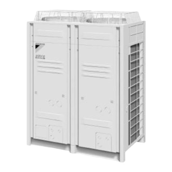
REYQ8-48PY1B
Daikin REYQ8-48PY1B Manuals
Manuals and User Guides for Daikin REYQ8-48PY1B. We have
2
Daikin REYQ8-48PY1B manuals available for free PDF download: Service Manual
Daikin REYQ8-48PY1B Service Manual (477 pages)
Heat Recovery 50Hz
Brand:
Daikin
| Category:
Heater
| Size: 18 MB
Table of Contents
Table of Contents
2
Introduction
7
Safety Cautions
7
Preface
11
Part 1 General Information
12
Model Names of Indoor/Outdoor Units
13
External Appearance
14
Indoor Units
14
Outdoor Units
15
Combination of Outdoor Units
16
Model Selection
17
Part 2 Specifications
20
Outdoor Units
21
Indoor Units
32
BS Units
68
Part 3 Refrigerant Circuit
69
Refrigerant Circuit
70
Reyq8P, 10P, 12P
70
Refrigerant Circuit Part
70
Reyq14P, 16P
72
REMQ8P (Multi 8HP)
74
REMQ10P, 12P (Multi 10, 12HP)
76
REMQ14P, 16P (Multi 14, 16HP)
78
BS Unit Functional Parts
80
Indoor Units
81
Functional Parts Layout
82
Reyq8P, 10P, 12P
82
Reyq14P, 16P
83
Remq8P
84
Remq10P, 12P
85
Remq14P, 16P
86
Refrigerant Flow for each Operation Mode
87
Part 4 Function
114
Function General
115
Symbol
115
Operation Mode
117
Basic Control
118
Normal Operation
118
Compressor PI Control
119
Electronic Expansion Valve PI Control
127
Step Control of Outdoor Unit Fans
127
Outdoor Unit Fan Control in Cooling Operation
128
Heat Exchanger Control
129
Special Control
130
Startup Control
130
Large Capacity Start up Control (Heating)
132
Oil Return Operation
133
Defrost Operation
137
Pump down Residual Operation
139
Standby
141
Stopping Operation
142
Protection Control
143
High Pressure Protection Control
143
Low Pressure Protection Control
145
Discharge Pipe Protection Control
147
Inverter Protection Control
148
STD Compressor Overload Protection
150
Other Control
151
Backup Operation
151
Demand Operation
151
Heating Operation Prohibition
151
Outline of Control (Indoor Unit)
152
Operation Flow Chart
152
Thermostat Control
154
Drain Pump Control
158
Control of Electronic Expansion Valve
160
Freeze Prevention
161
Heater Control (Optional PCB KRP1B
162
List of Swing Flap Operations
163
Hot Start Control (in Heating Operation Only)
164
Louver Control for Preventing Ceiling Dirt
165
Part 5 Test Operation
166
Test Operation
167
Installation Process
167
Procedure and Outline
168
Test Run
183
Operation When Power Is Turned on
200
Outdoor Unit PCB Layout
201
Field Setting
202
Field Setting from Remote Controller
202
Field Setting from Outdoor Unit
218
Emergency Operation
242
Part 6 Troubleshooting
247
Symptom-Based Troubleshooting
250
Troubleshooting by Remote Controller
253
The INSPECTION / TEST Button
253
Self-Diagnosis by Wired Remote Controller
254
Self-Diagnosis by Wireless Remote Controller
255
Inspection Mode
258
Remote Controller Service Mode
259
Test Run Mode
262
Remote Controller Self-Diagnosis Function
262
Troubleshooting by Indication on the Remote Controller
270
A0 " Indoor Unit: Error of External Protection Device
270
A1 " Indoor Unit: PCB Defect
271
A3 " Indoor Unit: Malfunction of Drain Level Control System (S1L)
272
A6 " Indoor Unit: Fan Motor (M1F) Lock, Overload
274
A6 " Indoor Unit : Malfunction of Indoor Unit Fan Motor
276
A7 " Indoor Unit: Malfunction of Swing Flap Motor (M1S)
280
A8 " Abnormal Power Supply Voltage
282
A9 " Electronic Expansion Valve Malfunction / Dust Clogging
283
A9 " Indoor Unit: Malfunction of Electronic Expansion Valve Coil
285
AF " Indoor Unit: Drain Level above Limit
287
AJ " Indoor Unit: Malfunction of Capacity Determination Device
288
C1 " Indoor Unit: Failure of Transmission (between Indoor Unit PCB and Fan PCB)
289
C4 " Indoor Unit: Malfunction of Thermistor (R2T) for Heat Exchanger
291
C5 " Indoor Unit: Malfunction of Thermistor (R3T) for Gas Pipes
292
C6 " Indoor Unit: Failure of Combination (between Indoor Unit PCB and Fan PCB)
293
C9 " Indoor Unit: Malfunction of Thermistor (R1T) for Suction Air
294
CJ " Indoor Unit: Malfunction of Room Temperature
295
Thermistor in Remote Controller
295
E1 " Outdoor Unit: PCB Defect
296
E3 " Outdoor Unit: Actuation of High Pressure Switch
297
E4 " Outdoor Unit: Actuation of Low Pressure Sensor
299
E5 " Outdoor Unit: Inverter Compressor Motor Lock
301
E6 " Outdoor Unit: STD Compressor Motor Overcurrent/Lock
303
E7 " Outdoor Unit: Malfunction of Outdoor Unit Fan Motor
304
E9 " Outdoor Unit: Malfunction of Electronic Expansion Valve Coil (Y1E~Y5E)
307
F3 " Outdoor Unit: Abnormal Discharge Pipe Temperature
309
F6 " Outdoor Unit: Refrigerant Overcharged
311
F9 " Outdoor Unit : Malfunction of BS Unit Electronic Expansion Valve
312
H7 " Outdoor Unit: Abnormal Outdoor Fan Motor Signal
314
H9 " Outdoor Unit: Malfunction of Thermistor (R1T) for Outdoor Air
316
J2 " Outdoor Unit: Current Sensor Malfunction
317
J3 " Outdoor Unit: Malfunction of Discharge Pipe Thermistor (R31T, R32T, R33T)
318
J4 " Outdoor Unit: Malfunction of Temperature Sensor for Heat Exchanger Gas (R2T or R11T)
319
J5 " Outdoor Unit: Malfunction of Thermistor (R8T or R10T) for Suction Pipe
320
J6 " Outdoor Unit: Malfunction of Thermistor (R4T or R12T) for Outdoor Unit Heat Exchanger
321
(R6T, R9T or R14T)
322
(R7T or R15T)
323
J9 " Outdoor Unit: Malfunction of Subcooling Heat Exchanger
324
Gas Pipe Thermistor (R5T or R13T)
324
J9 " Outdoor Unit: Malfunction of Subcooling Heat
324
Exchanger Gas Pipe Thermistor (R5T or R13T)
324
JA " Outdoor Unit: Malfunction of High Pressure Sensor
325
JC " Outdoor Unit: Malfunction of Low Pressure Sensor
327
L1 " Outdoor Unit: Malfunction of Inverter PCB
329
L4 " Outdoor Unit: Malfunction of Inverter Radiation Fin Temperature Rise
331
L5 " Outdoor Unit: Momentary Overcurrent of Inverter Compressor
334
L8 " Outdoor Unit: Momentary Overcurrent of Inverter Compressor
336
L9 " Outdoor Unit: Inverter Compressor Starting Failure
338
LC " Outdoor Unit: Malfunction of Transmission between
341
Inverter and Control PCB
341
P1 " Outdoor Unit: Inverter Over-Ripple Protection
344
P4 " Outdoor Unit: Malfunction of Inverter Radiation Fin
346
Temperature Rise Sensor
346
PJ " Outdoor Unit: Faulty Field Setting after Replacing Main PCB or Faulty Combination of PCB
348
U0 " Outdoor Unit: Refrigerant Shortage Alert
350
U1 " Reverse Phase, Open Phase
352
U2 " Outdoor Unit: Power Supply Insufficient or Instantaneous Failure
353
U3 " Outdoor Unit: Check Operation Is Not Executed
356
U4 " Malfunction of Transmission between Indoor Units and Outdoor Units
357
U5 " Indoor Unit: Malfunction of Transmission between Remote Controller and Indoor Unit
360
U7 " Outdoor Unit: Transmission Failure (Across Outdoor Units)
361
U8 " Indoor Unit: Malfunction of Transmission between Main and Sub Remote Controllers
367
U9 " Indoor Unit: Malfunction of Transmission between Indoor and Outdoor Units in the same System
368
UA " Improper Combination of Indoor and Outdoor Units
369
Indoor Units and Remote Controller
369
UC " Address Duplication of Centralized Controller
375
UE " Malfunction of Transmission between Centralized
376
Controller and Indoor Unit
376
UF " System Is Not Set yet
379
UH " Malfunction of System, Refrigerant System Address Undefined
380
Troubleshooting (OP: Centralized Remote Controller)
382
M1 " PCB Defect
382
M8 " Malfunction of Transmission between Optional Controllers for Centralized Control
383
M8 " Malfunction of Transmission between Optional
383
Controllers for Centralized Control
383
MA " Improper Combination of Optional Controllers for Centralized Control
384
Centralized Control
384
MC " Address Duplication, Improper Setting
386
Troubleshooting (OP: Unified ON/OFF Controller)
387
Operation Lamp Blinks
387
Display "Under Centralized Control" Blinks (Repeats Single Blink)
389
Display "Under Centralized Control" Blinks (Repeats Double Blink)
392
Display "Under Centralized Control" Blinks
392
(Repeats Double Blink)
392
Part 7 Appendix
407
Piping Diagrams
408
Outdoor Unit
408
Indoor Unit
413
BS Unit
418
Wiring Diagrams for Reference
419
Outdoor Unit
419
Field Wiring
424
Indoor Unit
427
BS Unit
440
List of Electrical and Functional Parts
442
Outdoor Unit
442
Indoor Side
446
Option List
451
Option List of Controllers
451
Option Lists (Outdoor Unit)
453
Piping Installation Point
454
The Example of a Wrong Pattern
455
Example of Connection
457
Thermistor Resistance / Temperature Characteristics
461
Pressure Sensor
463
Method of Checking the Inverter's Power Transistors and Diode Modules
464
Diode Modules
464
Part 8 Precautions for New Refrigerant (R-410A)
466
Precautions for New Refrigerant (R-410A)
467
Outline
467
Refrigerant Cylinders
469
Service Tools
470
Advertisement
Daikin REYQ8-48PY1B Service Manual (120 pages)
R-410 Heat Recovery 50HZ
Brand:
Daikin
| Category:
Heater
| Size: 8 MB
Table of Contents
Table of Contents
2
Introduction
7
Safety Cautions
7
Preface
11
Part 1 General Information
13
Model Names of Indoor/Outdoor Units
14
External Appearance
15
Indoor Units
15
Outdoor Units
16
Combination of Outdoor Units
17
Model Selection
18
Part 2 Specifications
22
Outdoor Units
22
Indoor Units
33
BS Units
66
Part 3 Refrigerant Circuit
67
Refrigerant Circuit
68
Reyq8P, 10P, 12P
68
Sienbe37
69
Reyq14P, 16P
70
REMQ8PY1 (Multi 8HP)
72
REMQ8P (Multi 8HP)
72
REMQ10PY1, 12PY1 (Multi 10, 12HP)
74
REMQ10P, 12P (Multi 10, 12HP)
74
REMQ14PY1, 16PY1 (Multi 14, 16HP)
76
BS Unit Functional Parts
78
Indoor Units
79
Functional Parts Layout
80
Reyq8P, 10P, 12P
80
Reyq14P, 16P
81
Remq8P
82
Remq10P, 12P
83
Remq14P, 16P
84
Refrigerant Flow for each Operation Mode
85
Oil Return Operation
88
Part Function
113
Low Pressure Protection Control
113
Function General
114
Symbol
114
Operation Mode
116
Basic Control
117
Normal Operation
117
Control of Electronic Expansion Valve
117
Compressor PI Control
118
Sienbe37
118
Outdoor Unit
119
Advertisement
Related Products
Daikin RDXYQ8T7V1B
Daikin RDXYQ5T7V1B
Daikin REYQ8P
Daikin REYQ8M7W1B
Daikin VRV III REYQ8PY1B
Daikin REYQ8P8Y1B
Daikin REYQ8T7Y1B
Daikin VRV III REYQ8PY1
Daikin VRV II REYQ8MY1B
Daikin REYQ8U7Y1B
Daikin Categories
Air Conditioner
Heat Pump
Chiller
Remote Control
Air Handlers
More Daikin Manuals
Login
Sign In
OR
Sign in with Facebook
Sign in with Google
Upload manual
Upload from disk
Upload from URL