Table of Contents
Advertisement
Advertisement
Table of Contents

Related Manuals for thomann Swissonic PA 3


Summary of Contents for thomann Swissonic PA 3
- Page 1 PA 3 power amplifier user manual...
- Page 2 Musikhaus Thomann Thomann GmbH Hans-Thomann-Straße 1 96138 Burgebrach Germany Telephone: +49 (0) 9546 9223-0 E-mail: info@thomann.de Internet: www.thomann.de 03.03.2017, ID: 382062...
-
Page 3: Table Of Contents
Table of contents Table of contents General information..........................4 1.1 Further information........................... 5 1.2 Notational conventions........................6 1.3 Symbols and signal words....................... 6 Safety instructions............................. 8 Features............................... 15 Installation and starting up........................ 16 Connections and controls........................21 Technical specifications........................26 Plug and connection assignment.................... -
Page 4: General Information
General information General information This manual contains important instructions for the safe operation of the unit. Read and follow the safety instructions and all other instructions. Keep the manual for future reference. Make sure that it is available to all those using the device. If you sell the unit please make sure that the buyer also receives this manual. -
Page 5: Further Information
General information 1.1 Further information On our website (www.thomann.de) you will find lots of further information and details on the following points: Download This manual is also available as PDF file for you to download. Use the search function in the electronic version to find the topics of Keyword search interest for you quickly. -
Page 6: Notational Conventions
General information 1.2 Notational conventions This manual uses the following notational conventions: Letterings The letterings for connectors and controls are marked by square brackets and italics. Examples: [VOLUME] control, [Mono] button. 1.3 Symbols and signal words In this section you will find an overview of the meaning of symbols and signal words that are used in this manual. - Page 7 General information Signal word Meaning DANGER! This combination of symbol and signal word indicates an immediate dangerous situation that will result in death or serious injury if it is not avoided. CAUTION! This combination of symbol and signal word indicates a pos‐ sible dangerous situation that can result in minor injury if it is not avoided.
-
Page 8: Safety Instructions
Safety instructions Safety instructions Intended use This unit amplifies audio frequency signals for the operation of passive loudspeakers. It is designed for professional use only. Use the device only as described in this user manual. Any other use or use under other operating conditions is considered to be improper and may result in personal injury or property damage. - Page 9 Safety instructions Safety DANGER! Danger for children Ensure that plastic bags, packaging, etc. are disposed of properly and are not within reach of babies and young children. Choking hazard! Ensure that children do not detach any small parts (e.g. knobs or the like) from the unit.
- Page 10 Safety instructions DANGER! Hazardous voltage Hazardous voltage may be present at cable ends and screw terminals. The connection of screw terminals as well as all maintenance and repair work on the electrical installation of the device must only be performed by qualified elec‐ trical personnel in volt-free condition.
- Page 11 Safety instructions CAUTION! Possible hearing damage With loudspeakers or headphones connected, the device can produce volume levels that may cause temporary or permanent hearing impairment. Do not operate the device permanently at a high volume level. Decrease the volume level immediately if you experience ringing in your ears or hearing impairment.
- Page 12 Safety instructions NOTICE! Operating conditions This device has been designed for indoor use only. To prevent damage, never expose the device to any liquid or moisture. Avoid direct sunlight, heavy dirt, and strong vibrations. NOTICE! Power supply Before connecting the device, ensure that the input voltage (AC outlet) matches the voltage rating of the device and that the AC outlet is protected by a residual current circuit breaker.
- Page 13 Safety instructions NOTICE! Magnetic fields The device generates strong magnetic fields that can interfere with the function of poorly shielded devices. The strongest magnetic fields are directly above and below the power amplifier. Therefore, never place sensitive devices such as pre- amplifiers, radio transmission systems, or tape decks directly above or below the power amplifier.
- Page 14 Safety instructions NOTICE! Possible damages by using an external battery Improper handling may cause an arc or short circuit between the bare ends of a live power cable to an external battery. This can destroy the battery and there is a fire hazard! If you use an external battery for power supply, connect the power cord to the screw terminal on the rear panel first.
-
Page 15: Features
Features Features Flexible high-performance power stage for PA application 240 W (RMS) Inputs: XLR, 1/4" phone socket (unbalanced), RCA sockets, screw terminals Outputs: – Screw terminals for loudspeakers, optionally in 4 Ω, 70 V or 100 V technology – Line output for connecting additional power stages (XLR, unbalanced 1/4" phone socket, RCA sockets, screw terminals) Protection circuits: DC short-circuit protection, overheat protection PA 3... -
Page 16: Installation And Starting Up
Installation and starting up Installation and starting up Unpack and carefully check that there is no transportation damage before using the unit. Keep the equipment packaging. To fully protect the device against vibration, dust and moisture during transportation or storage use the original packaging or your own packaging material suitable for transport or storage, respectively. - Page 17 Installation and starting up DANGER! Hazardous voltage Hazardous voltage may be present at cable ends and screw terminals. The connection of screw terminals as well as all maintenance and repair work on the electrical installation of the device must only be performed by qualified elec‐ trical personnel in volt-free condition.
- Page 18 Installation and starting up NOTICE! Magnetic fields The device generates strong magnetic fields that can interfere with the function of poorly shielded devices. The strongest magnetic fields are directly above and below the power amplifier. Therefore, never place sensitive devices such as pre- amplifiers, radio transmission systems, or tape decks directly above or below the power amplifier.
- Page 19 Installation and starting up Speaker connection You can choose to either connect low-ohm loudspeakers with a total impedance of 4 Ω or ELA speakers (70 V technology or 100 V technology). Observe the following diagram when con‐ necting the loudspeakers. The connectors are located under a removable cover. Replace this cover after connecting the speakers and before you turn on the power.
- Page 20 Installation and starting up DC connection The device can be supplied with 24 V DC voltage. Before connecting, ensure that the cable cross-sections are sufficient. Rack mounting The device has been designed for rack mounting in a standard 19-inch rack; it occupies two rack units.
-
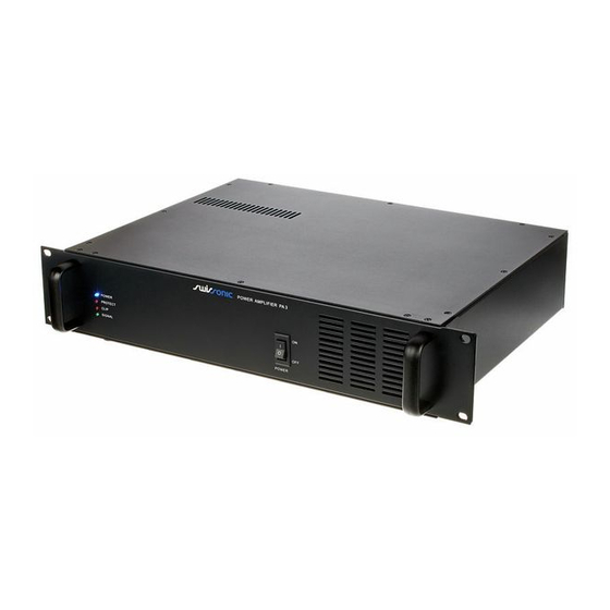
Page 21: Connections And Controls
Connections and controls Connections and controls Front panel PA 3... - Page 22 Connections and controls 1 LED panel [POWER] This LED shows that the device is turned on. [PROTECT] Lights up when one or more protective circuits have tripped or the device is defective. [CLIP] Lights up when the channel is overdriven. In this case, use the [INPUT GAIN] control to reduce the signal level until the LED goes out again.
- Page 23 Connections and controls Rear panel PA 3...
- Page 24 Connections and controls 3 [DC SW] Resettable fuse. The fuse shuts down when the power amp's current drain is too high or when the loudspeaker output is short-circuited. To reset, disconnect the connected speakers and turn the switch back on. If the switch trips again, there is a defect.
- Page 25 Connections and controls 7 [GROUND LIFT] If hum is caused by a ground loop, you can use this switch to disconnect the connection between the earth pin of the device and the signal ground of the device. 8 [LINK] Line level outputs for connecting additional devices (e.g. amplifiers, recording devices or active speakers), designed as RCA sockets, XLR chassis socket, screw terminals and 1/4"...
-
Page 26: Technical Specifications
Technical specifications Technical specifications Power output (RMS) 240 W Frequency response, ±1 dB 30 Hz … 20 kHz (0 / –3 dB) Amplification control –80 dB … 0 dB Signal-to-noise ratio > 85 dB Total harmonic distortion @ 50 % of maximum <... -
Page 27: Plug And Connection Assignment
Plug and connection assignment Plug and connection assignment Introduction This chapter will help you select the right cables and plugs to connect your valuable equip‐ ment in such a way that a perfect sound experience is ensured. Please note these advices, because especially in ‘Sound & Light’ caution is indicated: Even if a plug fits into the socket, an incorrect connection may result in a destroyed power amp, a short circuit or ‘just’... - Page 28 Plug and connection assignment Since the interference affects both cores equally, by subtracting the phase-shifted signals, the interfering signal is completely neutralized. The result is a pure signal without any noise inter‐ ference. 1/4" TS phone plug (mono, unbalanced) Signal Ground, shielding XLR plug (balanced) Ground, shielding...
- Page 29 Plug and connection assignment RCA connection Drawing and table indicate the pin assignment of an RCA plug. Signal Ground, shielding PA 3...
-
Page 30: Cleaning
Cleaning Cleaning Fan grids The fan grids of the device must be cleaned on a regular basis to remove dust and dirt. Before cleaning, switch off the device and disconnect AC-powered devices from the mains. Use a lint- free damp cloth for cleaning. Never use solvents or alcohol for cleaning. power amplifier... -
Page 31: Protecting The Environment
Protecting the environment Protecting the environment Disposal of the packaging mate‐ rial For the transport and protective packaging, environmentally friendly materials have been chosen that can be supplied to normal recycling. Ensure that plastic bags, packaging, etc. are properly disposed of. Do not just dispose of these materials with your normal household waste, but make sure that they are collected for recycling. - Page 32 Notes power amplifier...
- Page 33 Notes PA 3...
- Page 34 Notes power amplifier...
- Page 36 Musikhaus Thomann · Hans-Thomann-Straße 1 · 96138 Burgebrach · Germany · www.thomann.de...
Need help?
Do you have a question about the Swissonic PA 3 and is the answer not in the manual?
Questions and answers