Table of Contents
Advertisement
Quick Links
Advertisement
Table of Contents

Related Manuals for thomann the t.amp pro D4-500


Summary of Contents for thomann the t.amp pro D4-500
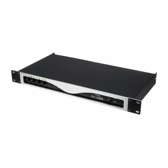
- Page 1 D4-500 digital power amplifier user manual...
- Page 2 Musikhaus Thomann e. K. Treppendorf 30 96138 Burgebrach Germany Telephone: +49 (0) 9546 9223-0 E-mail: info@thomann.de Internet: www.thomann.de 13.08.2012...
-
Page 3: Table Of Contents
Table of contents Table of contents General notes............................... 4 Safety instructions............................. 7 Features............................... 12 Installation and starting up........................ 13 4.1 Pin assignment..........................14 Connections and operating elements................... 18 Power consumption..........................23 Technical specifications........................24 Protecting the environment......................26 D4-500... -
Page 4: General Notes
General notes General notes This user manual contains important information on safe operation of the device. Read and follow all safety notes and all instructions. Save this manual for future reference. Make sure that it is available to all persons using this device. If you sell the device to other users, be sure that they also receive this manual. - Page 5 General notes Signal word Meaning DANGER! This combination of symbol and signal word indicates an immediate dangerous situation that will result in death or serious injury if it is not avoided. CAUTION! This combination of symbol and signal word indicates a possible dangerous situation that can result in minor injury if it is not avoided.
- Page 6 General notes Warning signs Type of danger Warning – danger zone. digital power amplifier...
-
Page 7: Safety Instructions
Safety instructions Safety instructions Intended use This device amplifies electric audio frequency signals to operate passive speakers. Use the device only as described in this user manual. Any other use or use under other operating con‐ ditions is considered to be improper and may result in personal injury or property damage. No liability will be assumed for damages resulting from improper use. - Page 8 Safety instructions DANGER! Electric shock caused by high voltages inside Within the device there are areas where high voltages may be present. Never remove any covers. There are no user-serviceable parts inside. DANGER! Electric shock caused by short-circuit Always use proper ready-made insulated mains cabling (power cord) with a pro‐ tective contact plug.
- Page 9 Safety instructions CAUTION! Possible hearing damage The device can produce volume levels that may cause temporary or permanent hearing impairment. Over an extended period of time, even levels that seem to be uncritical can cause hearing damage. Decrease the volume level immediately if you experience ringing in your ears or hearing impairment.
- Page 10 Safety instructions NOTICE! Operating conditions This device has been designed for indoor use only. To prevent damage, never expose the device to any liquid or moisture. Avoid direct sunlight, heavy dirt, and strong vibrations. NOTICE! Power supply Before connecting the device, ensure that the input voltage (AC outlet) matches the voltage rating of the device and that the AC outlet is protected by a residual current circuit breaker.
- Page 11 Safety instructions NOTICE! Magnetic fields The device generates strong magnetic fields that can interfere with the function of poorly shielded devices. The strongest magnetic fields are directly above and below the power amplifier. Therefore, never place sensitive devices such as pre- amplifiers, radio transmission systems, or tape decks directly above or below the power amplifier.
-
Page 12: Features
Features Features Output power – 4 × 500 W @ 4 W 4 × 250 W @ 8 W – 4 inputs, 4 outputs Frequency response 20 Hz to 20 kHz 19" rackable (1 RU, installation depth 240 mm) digital power amplifier... -
Page 13: Installation And Starting Up
Installation and starting up Installation and starting up Unpack and check carefully there is no transportation damage before using the unit. Keep the equipment packaging. To fully protect the device against vibration, dust and moisture during transportation or storage use the original packaging or your own packaging material suitable for transport or storage, respectively. -
Page 14: 4.1 Pin Assignment
Installation and starting up 4.1 Pin assignment XLR connections for signal You can use XLR and 1/4" plugs with balanced or unbalanced wiring. In the following, we will inputs give you an overview of the various options. Drawings and tables indicate the XLR pin assign‐ ment. - Page 15 Installation and starting up Unbalanced wiring: Ground, shielding Signal Bridged to pin 1 1/4" phone sockets for signal Drawings and tables indicate the pin assignment of 1/4" phone plugs to be used. inputs Unbalanced wiring of a TS plug: Signal Ground, shielding D4-500...
- Page 16 Installation and starting up Unbalanced wiring of a TRS plug: Signal 2, 3 Ground, shielding Balanced wiring of a TRS plug: Positive signal (+) Negative signal (–) Ground, shielding digital power amplifier...
- Page 17 Installation and starting up NL4 mounting connectors The drawing alongside shows the pin assignment of the lockable NL4 mounting connectors. D4-500...
-
Page 18: Connections And Operating Elements
Connections and operating elements Connections and operating elements Front panel digital power amplifier... - Page 19 Connections and operating elements 1 ON | OFF Main switch to turn the device on or off. 2 LED Power This LED indicates, that the unit is operational and lights up constantly as soon as the device is switched on. 3 LEDs –10 dB and –20 dB These LEDs indicate the intensity of the input signal (–10 dB or –20 dB).
- Page 20 Connections and operating elements 5 LEDs Fault Error indication for channels CH-A to CH-D. These LEDs light up when one of the protective circuits triggers (see Ä Chapter 7 ‘Technical specifications’ on page 24). When turning the device on, the LEDs light up for three seconds. During this time, there is no signal present at the output yet .
- Page 21 Connections and operating elements Rear panel D4-500...
- Page 22 Connections and operating elements 8 IEC chassis connector with fuse holder for operating voltage supply. 9 INPUT CH-A …-D Lockable XLR / 1/4" mounting combo connectors for signal inputs. 10 OUTPUT CH-A …-D Lockable NL4 mounting connectors for signal outputs. 11 Pushbutton Stereo | Parallel | Bridge Toggle switch for the operating modes ‘Stereo’...
-
Page 23: Power Consumption
Power consumption Power consumption The following table shows the typical current consumption depending on the output power level (RMS value A Load 1/8 power 1/3 power Full power (pink noise) (pink noise) (sine wave) 8 W (× 4) 130 W / 1.3 A 190 W / 1.9 A 640 W / 4.2 A 4 W (×... -
Page 24: Technical Specifications
Technical specifications Technical specifications Rated output power @ 8 W 4 × 250 W (THD = 1 %, 1 kHz) Rated output power @ 4 W 4 × 500 W (THD = 1 %, 1 kHz) Max. voltage swing (RMS) 35 V (THD = 1 %, 1 kHz) Slew rate (1 kHz) 26 V/ms... - Page 25 Technical specifications Signal-to-noise ratio 107 dB (A-weighted) Protective circuits VHF, direct voltage, temperature, short circuit, Undervoltage, overcurrent, lim‐ iter Operating voltage supply AC 230 V , 50/60 Hz Power consumption Ä Chapter 6 ‘Power consumption’ on page 23 Dimensions 1 RU in a 19" rack, installation depth 240 mm Weight 4.6 kg D4-500...
-
Page 26: Protecting The Environment
Protecting the environment Protecting the environment Disposal of the packaging mate‐ rial For the transport and protective packaging, environmentally friendly materials have been chosen that can be supplied to normal recycling. Ensure that plastic bags, packaging, etc. are properly disposed of. Do not just dispose of these materials with your normal household waste, but make sure that they are collected for recycling. - Page 28 Musikhaus Thomann e.K. · Treppendorf 30 · 96138 Burgebrach · Germany · www.thomann.de...
Need help?
Do you have a question about the the t.amp pro D4-500 and is the answer not in the manual?
Questions and answers