
Related Manuals for Wilbur Curtis Company G4CBHS


Summary of Contents for Wilbur Curtis Company G4CBHS
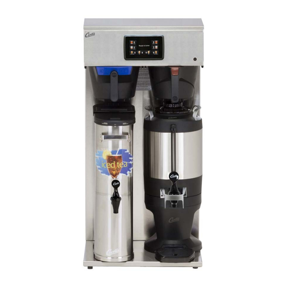
- Page 1 USER’S GUIDE G4 High Volume Combo Brewers READ AND SAVE THESE INSTRUCTIONS NOTICE TO INSTALLER: Please leave this booklet with the machine. 022317A FC3 - G4CBHS/G4CBHT, FRONT COVER F-10002 revA...
-
Page 2: Table Of Contents
CONTENTS ....................FS3 ............................... IS2 ..........................II2 ..................II8 ..............................OI2 ..........................CI1 ......................CI5 ........................CI6 ............................................................................... IP3 ................IP19 ................IP20 ..........................ES7 ..........................ES8 ....................................................................................................................EC1 ..............................Contact Information Wilbur Curtis Co., Inc. 6913 Acco Street | Montebello, CA 90640 US Phone: 323-837-2300 | Toll Free: 800-421-6150 Email: csrassistance@wilburcurtis.com | Web: www.wilburcurtis.com . -
Page 3: Fs3
• Brew Volume (coffee) = Large-Medium-Small • Minimum Brew Temperature = 195°F • Brew Volume (tea) = Large-Small • Water Bypass (coffee) = On LARGE and MEDIUM • Energy Save Mode = Off brew only G4CBHS/G4CBHT, KEY FEATURES/SPECS/SYSTEM REQUIREMENTS 092016A... -
Page 4: Is2
IMPORTANT SAFEGUARDS Symbols This is the safety alert symbol. It is used to alert you to potential physical injury hazards. Obey all safety messages that follow this symbol to avoid possible injury or death. DANGER - Indicates a hazardous situation which, if not avoided, will result in death or serious injury. WARNING - Indicates a hazardous situation which, if not avoided, could result in death or serious injury. -
Page 5: Ii2
INSTALLATION INSTRUCTIONS WARNING: WARNING: properly grounded. NOTICE: SPECIFICATIONS section. IMPORTANT: Installation Instructions Installation Requirements • A secure surface capable of supporting the weight of the brewer. • For brewers without an attached cord set: Appropriately sized, UL listed, grounding type power cable to meet enough •... -
Page 6: Ii8
INSTALLATION INSTRUCTIONS Installation Leveling WARNING: Use the leveling legs to level the brewer only. Do not use them to adjust brewer height. Do not extend them higher than necessary. Position the brewer on the counter top. Level it left to right and front to back by turning the bottom of the legs. - Page 7 INSTALLATION INSTRUCTIONS Connect the Brewer Wiring (cont.) Brewers With A Cord Set Attached 12 Connect the power cord to the appropriate electrical outlet. WARNING: Connect the power cord to the appropriate type and size electrical outlet. If the electrical outlet is not compatible with the power cord, have it upgraded by a licensed electrician.
-
Page 8: Oi2
OPERATING INSTRUCTIONS Brewing Instructions WARNING - TO AVOID SCALDING, AVOID SPLASHING. Keep body parts clear of the brewer during brewing. Do not remove the brew basket while “Brewing” appears on the display. WARNING - DO NOT refrigerate unused tea overnight for later consumption. The G4 Combo Brewer is factory preset for optimal performance. -
Page 9: Ci1
CLEANING INSTRUCTIONS WARNING: HOT SURFACES - To avoid injury, allow the brewer and dispenser(s) to cool before cleaning. NOTICE - Do not use cleaning liquids, compounds or powders containing chlorine (bleach) or corrosives. USE OF THESE PRODUCTS WILL VOID THE WARRANTY. Cleaning The Brewer - Daily WARNING: DO NOT immerse the brewer in water or any other liquid. -
Page 10: Ci5
CLEANING INSTRUCTIONS Cleaning the 1.0 Gallon or 1.5 Gallon Thermal Dispensers (Daily) WARNING: DO NOT immerse thermal dispensers in water or any other liquid. Do not place the ThermoPro dispenser in a dishwasher. Placing the ThermoPro dispenser in a dishwasher will void the warranty. To clean, prepare a mild solution of detergent and warm water. -
Page 11: Ci6
CLEANING INSTRUCTIONS Cleaning the Tea Dispenser (Daily) Cleaning the Container Prepare a mild solution of detergent and warm water. Remove the dispenser from the brewer and remove the lid. Rinse. Wash - Wipe the exterior surfaces with a sponge and the detergent solution to remove spills and debris. - Page 12 PROGRAMMING GUIDE Touchscreen Control Module The touchscreen turns on whenever power is provided to the brewer and the rear toggle switch is on. The symbol buttons on the screen control operation and programming. Pressing the on-screen symbols and buttons with Status lights Brew Buttons Control symbols - all...
- Page 13 PROGRAMMING GUIDE Programming SELECTIONS FOR COFFEE BREWER MODELS Model Select Recipes Control Settings Brew Settings Settings Summary Exit Coffee Gemini Gemini IF One Batch Single Gourmet Std ThermoPro Two Batch Twin Light Roast By Volume/Time Milano Three Batch Dark Roast Pre/Pulse Omega High Yield...
- Page 14 PROGRAMMING GUIDE USB - Easy Programming program each step individually using the touchscreen. This process also makes it easy to quickly standardize the IMPORTANT: completely Uploading the Software to the Flash Drive as desired. Downloading the Software to the Brewer from the Flash Drive Select the (identical) brewer you wish to make program changes to.
- Page 15 ROUGH-IN DRAWINGS G4CBHS - G4 Single High Volume Combo Brewer 9.11 in 23.1 cm 36.71 in 93.2 cm 24.31 in 23.65 in 22.99 in 61.7 cm 60.1 cm 58.4 cm 5.43 in 13.8 cm 10.00 in 20.84 in 1.29 in 52.9 cm...
- Page 16 ILLUSTRATED PARTS/RECOMMENDED PARTS Supplies and Accessories - All Models WC-29050 - Spray Head CAB-1 - Cleaning Brush Sold by the case G4CBHS - Main Chassis - Exploded View SEE SECTION IP25 G4CBHS/G4CBHT, ILLUSTRATED PARTS/RECOMMENDED PARTS 090616NC...
-
Page 17: Ip3
ILLUSTRATED PARTS/RECOMMENDED PARTS G4CBHS - Main Chassis - Parts List ITEM # PART # DESCRIPTION ITEM # PART # DESCRIPTION COVER, TOP ALPGT/D500GT/D60GT TLP/TCTS/CBS/ WC-13463-102 HARNESS ASSY, COMPLETE G4CBHS WC-58117 GEMSS WC-10000 CONTROL MODULE, TOUCH SCREEN G4 WC-61607 COVER, FRONT CBHVS... - Page 18 ILLUSTRATED PARTS/RECOMMENDED PARTS G4CBHT - Main Chassis - Exploded View SEE SECTION IP26 G4CBHS/G4CBHT, ILLUSTRATED PARTS/RECOMMENDED PARTS 090616NC...
- Page 19 SPRAYHEAD, AMBER ADVANCED FLOW WC-8559 QUICK DISCONNECTS WC-37122 KIT, DUMP VALVE RIGHT WC-5310 TUBE, 5/16 ID x 1/8W SILICONE VALVE, BY-PASS, NON-ADJUSTABLE WITH WC-844-101 WC-5231 COMPOUND, SILICONE 5 OZ RESTRICTOR (WC-2945) WC-37255 KIT, DUAL VALVE WATER INLET G4CBHS/G4CBHT, ILLUSTRATED PARTS/RECOMMENDED PARTS 090616NC...
- Page 20 ILLUSTRATED PARTS/RECOMMENDED PARTS IP25 WC-62080 - Tank Assembly WC-62080 - Tank Assembly - Parts List ITEM # PART # DESCRIPTION ITEM # PART # DESCRIPTION WC-54290DV-102 TANK, ASSY CBHS/CBHS67144 THERMOSTAT, HI LIMIT HEATER CONTROL WC-522 DPST 277V 40A WC-62080 TANK COMPLETE, CBHS/CBHS67144 WC-37365 KIT, FITTING TANK INLET WC-5853-102...
- Page 21 ILLUSTRATED PARTS/RECOMMENDED PARTS IP26 WC-62033 - Tank Assembly WC-62033 - Tank Assembly - Parts List ITEM # PART # DESCRIPTION ITEM # PART # DESCRIPTION WC-54287 TANK, ASSY TPS1T/GEMTS WC-4382 GUARD, SHOCK HTNG ELMNT DOUBLE WC-62033 TANK, COMPLETE GEMTS W/ULTEM FITTINGS THERMOSTAT, HI LIMIT HEATER CONTROL DPST WC-522 277V 40A...
-
Page 22: Es7
ELECTRICAL SCHEMATICS G4CBHS - 110/220 to 120/240 Volts (UPM) Pin Assignments 120V Hot Input 120V Hot Input Brew Valve Right Not Used 120V Neut ral Inlet Valve Not Used Not Used Not Used 10 Not Used 11 Not Used 12 Not Used... -
Page 23: Es8
ELECTRICAL SCHEMATICS G4CBHT - 208 to 240 Volts (UPM) Pin Assignments 120V Hot Input 120V Hot Input Brew Valve Right Brew Valve Left 120V Neut ral Inlet Valve Not Used Not Used Not Used 10 Not Used 11 Not Used 12 Not Used 13 Dilut ion Right 14 Dilut ion Left... - Page 24 TROUBLESHOOTING GUIDE WARNING: Electric Shock Hazard - Scald and Burn Hazard - IMPORTANT: always check all Valve Test Procedure Troubleshooting Guidelines • • • • Valve Test Procedure in either direction Water Not Hot Enough replace the temperature sensor Water Heats More Slowly Than Usual During Brewing...
- Page 25 TROUBLESHOOTING GUIDE No Power - Display Not Lit Water Tank Does Not Fill Brewer Does Not Start When Brew Button is Pressed Brewing Brewing Water Too Hot (Boiling or Excessive Steaming) IMPORTANT: Over Temp Over Temp Sensor or Ready to Brew Sensor Error Message Heating Heating...
- Page 26 TROUBLESHOOTING GUIDE Water Tank Does Not Fill IMPORTANT: Coffee/Tea Too Strong Dispenser Not Filled To Normal Level During Brewing Dispenser Not Filled To Normal Level During Brewing sure that the spray head is correctly aligned and that the tubing is routed properly to allow for maximum water...
- Page 27 TROUBLESHOOTING GUIDE All Of The Time No Water/Tea Flows From Brewer During Brewing Water Tank Does Not Fill Low Water Flow Warning Water Level Error Message Water Level Error Message “Internal Error 1” Message on Display “Internal Error 2” Message on Display PROGRAMMING GUIDE...
- Page 28 TROUBLESHOOTING GUIDE Water Does Not Heat At All Check to see if the water level in the tank is in contact with the water level probe. If not, see Tank Does Not Fill. • The water will not heat unless it is in contact with the probe. If the water heats, but is not hot enough, see Water Not Hot Enough.
- Page 29 TROUBLESHOOTING GUIDE TG11 Overview The G4 control module diagnostics can be used to detect electrical circuit failures in the brewer. When a circuit Using the Diagnostics The MAIN MENU Control Settings. Diagnostics Curtis logo Auto Test to test all circuits. If a button is highlighted green the DIAGNOSTICS Left Auto Test...
-
Page 30: Ec1
ERROR CODES Warning Messages - Allows Brewer to Continue Brewing MESSAGE DISPLAY WARNING DESCRIPTION CAUSE Brew count “Gallons Since Reset” exceeds programmed Maintenance Required Maintenance Required preventative maintenance period. If the Inlet valve remains on longer than XX seconds (during the brew cycle only) and repeats TWICE during that brew cycle. - Page 31 PRODUCT WARRANTY years, parts and labor, from original date of purchase on digital control boards CONDITIONS & EXCEPTIONS • Adjustments and cleaning: The resetting of safety thermostats and circuit breakers, programming and temperature adjustments are the responsibility of the equipment owner. The owner is responsible for proper cleaning and regular maintenance of this equipment. •...
Need help?
Do you have a question about the G4CBHS and is the answer not in the manual?
Questions and answers