
Related Manuals for Espa SPEEDRIVE

Summary of Contents for Espa SPEEDRIVE
- Page 1 SPEEDRIVE INSTRUCTIONS MANUAL INSTRUCTIONS MANUAL INSTRUCTIONS MANUAL INSTRUCTIONS MANUAL...
-
Page 2: Table Of Contents
Safety warning. Safety warning. Safety warning. Safety warning. The following symbols shown beside a paragraph represent danger warnings associated to the failure to comply with the corresponding instructions. DANGER! DANGER! Not observing this precaution involves a risk of electrocution. DANGER! DANGER! Risk of Risk of... -
Page 3: General Information
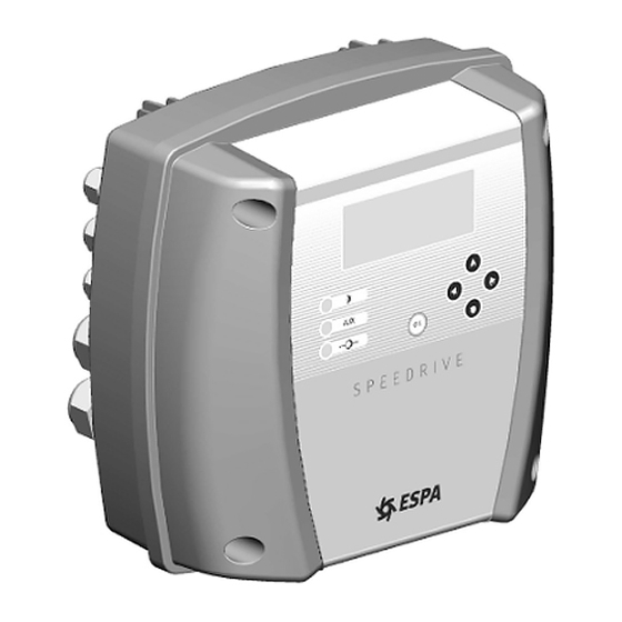
1) GENERAL INFORMATION. 1) GENERAL INFORMATION. 1) GENERAL INFORMATION. 1) GENERAL INFORMATION. The Speedrive inverters have been designed to adjust the speed of three three- - - - phase motors phase motors used with water pumps. three three phase motors phase motors The inverter receives a signal from the pressure transducer that is proportional to the installation's pressure. -
Page 4: Installation
3.2.1) Speedrive with single 3.2.1) Speedrive with single 3.2.1) Speedrive with single 3.2.1) Speedrive with single- - - - phase input (Figure 1): phase input (Figure 1): phase input (Figure 1): phase input (Figure 1): The motor must be connected to a 230 V power supply source. -
Page 5: Installation On The Pump
3.3) Installation on the pump. 3.3) Installation on the pump. The Speedrive is installed on the motor with a special supplied adapter. The inverter is cooled with the use of the motor's cooling elements. The unit has been designed for vertical and horizontal installation. - Page 6 3.3.2) Speedriv 3.3.2) Speedriv 3.3.2) Speedriv 3.3.2) Speedrive. e. e. e. Installation of the Speedrive on the adapter. Use the screws (1) supplied. Torque: 3 Nm. Single Single Single Single- - - - Phase Version Phase Version Phase Version Phase Version...
-
Page 7: Power Supply Connection
3.4) Power supply connection. 3.4) Power supply connection. 3.4) Power supply connection. 3.4) Power supply connection. DANGER. Risk of electrocution. Connection and grounding are compulsory. All electrical connections will be in accordance with the IEC-60364 Regulations (electrical installation in buildings) or the regulations in force in the destination country and local regulations. The power supply line of equipment must be adequately protected. -
Page 8: Signals Wires Connection
3.5) Signals wires connection. 3.5) Signals wires connection. 3.5) Signals wires connection. 3.5) Signals wires connection. Single Single Single Single- - - - phase version phase version phase version phase version Three Three Three Three- - - - Phase Version Phase Version Phase Version Phase Version... -
Page 9: Operating Modes
Espa ESD pumps and Espa pressure booster sets are pre Espa ESD pumps and Espa pressure booster sets are pre Espa ESD pumps and Espa pressure booster sets are pre- - - - configured in origin with an optimum pressure set configured in origin with an optimum pressure set... -
Page 10: Description Of The Menus
MANUAL OPERATION MANUAL OPERATION MANUAL OPERATION It shows the system pressure and Speedrive output frequency. Press ▲ ON, to activate the pump. Start-up is always performed at 15Hz. Press▼ OFF, to stop the pump. Press◄ or ►, to adjust the frequency. - Page 11 MAXIMUM MOTOR CURRENT MAXIMUM MOTOR CURRENT MAXIMUM MOTOR CURRENT MAXIMUM MOTOR CURRENT Maximum operating current of the motor. Adjust in accordance with the motor's data plate, plus 10%. Note: This screen only appears in the initial preset or retrieving the factory settings NOMINAL PRESSURE NOMINAL PRESSURE NOMINAL PRESSURE...
- Page 12 Adjust in accordance with the motor's data plate, plus 10%. Adjust in accordance with the motor's data plate, plus 10%. For auxiliary pumps equipped with "SPEEDRIVE" box this parameter must be regulated individually, for each equipment. The value of this screen is ignored.
- Page 13 SUBMENU USED TO RESET METERS (password SUBMENU USED TO RESET METERS (password SUBMENU USED TO RESET METERS (password SUBMENU USED TO RESET METERS (password ◄◄◄) ) ) ) RESET METER RESET METER RESET METER RESET METER Select "Yes" and click OK OK to reset all meters.
- Page 14 DIFFERENTIAL PRESSURE DIFFERENTIAL PRESSURE DIFFERENTIAL PRESSURE DIFFERENTIAL PRESSURE Difference between the set and start-up pressure. For ex. : 3 bars set – 0.5 bars differential = 2.5 bars start-up MAXIMUM MOTOR CURRENT MAXIMUM MOTOR CURRENT MAXIMUM MOTOR CURRENT MAXIMUM MOTOR CURRENT Maximum configured current/ Present current STOP FREQUENCY STOP FREQUENCY...
-
Page 15: Protection And Errors
The pressure transducer connected to the unit is not working properly ERROR The system will stop. (For booster sets, if other transducers are connected to Speedrive slaves, the booster will not stop and automatically switch to another transducer) - 15 -... -
Page 16: Electronic Circuit Failure
7) MULTIPLE OPERATION. 7) MULTIPLE OPERATION. The Speedrive inverter can control more up to 4 pumps, equipped with various Espa solutions, for a multiple pump booster set control. a) Booster set with "On-Off" auxiliary pumps , equipped with "ELV" box . -
Page 17: Booster Set With Inverter Regulated Auxiliary Pumps
ELV as needed Respect the polarity of the RS-485connection: Configuration. Configuration. Configuration. Configuration. Set Speedrive menus as follows: AUXILIARY PUMP AUXILIARY PUMP AUXILIARY PUMP AUXILIARY PUMP Press ► (Adjust) for the adjustment of the parameters that govern to the auxiliary pumps. - Page 18 The Speedrive installation and electrical wiring is done as described in this manual. The connection of the pressure transducer must be made solely on the "Master" Speedrive. A 2-wire twisted and shielded cable 0.5mm2 section must make the communication between devices.
- Page 19 Programming cascade spreads auxiliary pumps. DELAY OFF. Set the desired delay time in the stop sequence of auxiliary pumps. Programming cascade spreads auxiliary pumps. Set slave Speedrive menu as follows: MOTOR FREQUENCY MOTOR FREQUENCY MOTOR FREQUENCY MOTOR FREQUENCY Configuration of the nominal frequency of the motor, 50Hz or 60Hz.
-
Page 20: Main Components
9.3) OTHER INSTALLATIONS. 9.3) OTHER INSTALLATIONS. Speedrive module has been designed, and is certified, for united installation to the pump electric motor. Any other configuration or installation can be subject to additional certifications. ESPA 2025 SL disclaims all liability for uses not covered in this manual. -
Page 21: Menu Diagram
10) MENU DIAGRAM 10) MENU DIAGRAM 10) MENU DIAGRAM 10) MENU DIAGRAM - 21 -... - Page 22 - 22 -...
- Page 23 - 23 -...
- Page 24 ESPA 2025, S.L. C/ Mieres, s/n – 17820 BANYOLES GIRONA – SPAIN www.espa.com Cod.: 155854 Cod.: 155854 Cod.: 155854 Cod.: 155854 11- - - - 2010/05 2010/05 2010/05 2010/05...
Need help?
Do you have a question about the SPEEDRIVE and is the answer not in the manual?
Questions and answers