Table of Contents
Advertisement
Advertisement
Table of Contents

Subscribe to Our Youtube Channel
Summary of Contents for Midland SD-225V2
- Page 1 User’s Guide SD-225 Series 16 Channel UHF/VHF Data Radio www.midlandradio.com...
- Page 2 Radio Frequency (RF) electromagnetic energy emitted by FCC regulated equipment. Midland Radio Corporation subscribes to the same safety standard for the use of its products. Proper operation of this radio will result in user exposure far below the Occupational Safety and Health Act (OSHA) and FCC limits.
-
Page 3: Table Of Contents
Connection Overview ............8 External Interface ............... 10 DB9 Radio Interface Connector Details ......10 Setup and Operation.............. 12 Mounting................12 Channel Selection .............. 12 Status LED ................. 13 Specifications................. 14 Warranty Statement ............... 15 © 2006, Midland Radio Corporation... -
Page 4: Conventions And Symbols In This Book
This symbol marks a “note”. Notes are hints or tips which offer additional information to help you. Disclaimer Midland Radio Corporation is committed to continuous quality improvements, for this reason specifications may change without prior notice. Every effort has been made to ensure that the information in this document is complete, accurate, and up-to-date. - Page 5 Do not allow the antenna to touch or come in very close proximity with the eyes, face, or any exposed body parts while the radio is transmitting. The above warning list is not intended to include all hazards that may be encountered when using this radio. © 2006, Midland Radio Corporation...
-
Page 6: Introduction
Radio Models The SD-225 data radio is available in three frequency ranges. SD-225V2: 5 W, VHF high band, 148-174 MHz SD-225U1: 5 W, UHF high band, 400-440 MHz SD-225U2: 5 W, UHF high band, 440-480 MHz Radio Features... -
Page 7: Recommended Accessories And Options
Basic radio controls (transmit mode, receive mode, channel change, and modem test) are available via serial commands. Recommended Accessories and Options Software PC programming and adjustment software ACC-917 Cables USB PC programming cable ACC-2025 Options Bell 202/V.23 internal 1200 baud modem ACC-512? © 2006, Midland Radio Corporation... -
Page 8: Radio Connections
SD-225. Pin 6 is normally +5Vdc and switches to 0V when a signal exceeding the programmed squelch threshold is received. If CTCSS/DCS is programmed on the channel, the CTCSS/DCS must also be © 2006, Midland Radio Corporation... - Page 9 9 is typically used. Pin 9 is adjusted for a nominal 1 Vrms into an 8Ω load, when receiving a 1 KHz audio signal modulated at 60%. RV403 may be used to adjust the pin 9 output level. © 2006, Midland Radio Corporation...
-
Page 10: External Interface
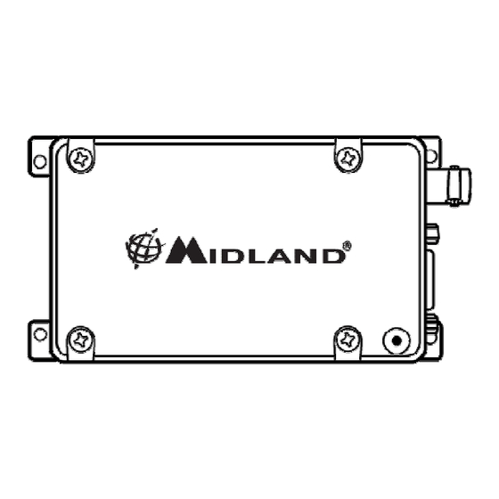
SD-225 User’s Guide External Interface 1.2 in 4.6 in DB9 male: modulation input, demodulation output, control inputs and power supply. BNC female: antenna connection. DB9 Radio Interface Connector Details © 2006, Midland Radio Corporation... - Page 11 RS232 input (serial control Also used for serial control data input. connection) input) SPK_OUT Filtered and de-emphasized audio output. Analog signal Speaker (audio) 1KHz audio @ 60% demodulation output deviation produces nominal 1Vrms into 8Ω © 2006, Midland Radio Corporation...
-
Page 12: Setup And Operation
The mounting hole center to center dimensions are shown above. The RF cabling should be routed separately from the control cabling to avoid interference. Channel Selection SW401 CH13 CH10 CH14 CH11 CH15 CH12 CH16 © 2006, Midland Radio Corporation... -
Page 13: Status Led
Program read Continuous red flash Program write Continuous green flash Squelch set Initial data load Green orange red Open level set Three green flashes Close level set Two green flashes Squelch level save One green flash © 2006, Midland Radio Corporation... -
Page 14: Specifications
60 dB (±12.5 KHz) / 70 dB (±25 KHz) Spurious emissions < -30 dBm FM hum & noise 34 dB NB / 40 dB WB Audio response per EIA/TIA-603 specs Audio distortion (1KHz @ 40%dev.) < 3% 50 Ω RF output impedance © 2006, Midland Radio Corporation... -
Page 15: Warranty Statement
Midland is not responsible for any ancillary equipment attached to or used in conjunction with Midland products. Midland offers to the original end user a Two (2) Year Limited Warranty on Midland Business and Industrial radio products. Accessories carry a One (1) Year Limited Warranty. - Page 16 This device complies with Part 15 of the FCC Rules. Operation is subject to the condition that this device does not cause harmful interference. This radio operates in FCC regulated frequency bands. All radios must be licensed by the FCC before use. Because this radio contains a transmitter, Federal law prohibits unauthorized use or adjustments of this radio.


Need help?
Do you have a question about the SD-225V2 and is the answer not in the manual?
Questions and answers