Table of Contents
Advertisement
Quick Links
Advertisement
Table of Contents

Summary of Contents for SystemAir SYSVRF WALL 15 Q
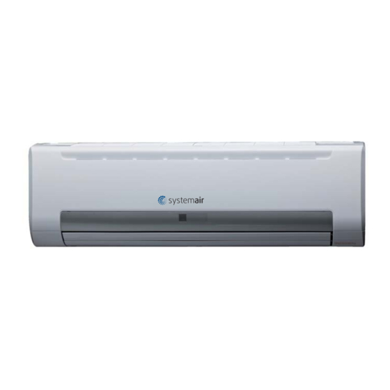
- Page 1 SYSVRF WALL Wall-mounted VRF indoor unit INSTALLATION MANUAL...
-
Page 2: Table Of Contents
CONTENTS PAGE When installing the unit in a small room, take measures against to keep refrigerant concentration from exceeding allowable safety limits in the event of refrigerant leakage. PRECAUTIONS......................1 Contact the place of purchase for more information. INSTALLATION INFORMATION................2 Excessive refrigerant in a closed ambient can lead to oxygen deficiency. -
Page 3: Installation Information
2. INSTALLATION INFORMATION If the refrigerant leaks during installation, ventilate the area immediately. To install properly, please read this "installation manual" at Toxic gas may be produced if the refrigerant comes into the first. place contacting with fire. The air conditioner must be installed by qualified persons. After completing the installation work, check that the refrigerant does not leak. -
Page 4: Attached Fittings
3. ATTACHED FITTINGS Please check whether the following fittings are of full scope. If there are some spare fittings , please restore them carefully. NAME SHAPE QUANTITY FUNCTION 1. Remote controller manual 2. Screw ST3.9x25 for installation board Secure the installation board 3. -
Page 5: Inspecting And Handling The Unit
4. INSPECTING AND HANDLING THE UNIT At delivery, the package should be checked and any damage should 5.2 Drilling A Hole and Mounting Installation be reported immediately to the carrier claims agent. Board When handling the unit, take into account the following: Installation Board and Its Direction (unit: mm) Fragile, handle the unit with care. - Page 6 When connecting extension drain hose,insulate the Incorrect installation connecting part of extension drain hose with a shield pipe Wall mounting board Shield pipe of indoor unit horizontal line Extension drainhose Drain hose Fig.5-6 Connection pipe Left piping mounting board of indoor unit Left back piping Right piping Right back piping...
-
Page 7: Refrigerant Pipe Installation
6. REFRIGERANT PIPE INSTALLATION Piping and bandaging Wind the connective cable, drain hose and wiring with tape securely, evenly as shown below. CAUTION Because the condensed water from rear of the indoor unit is Ventilate the air if there was any refrigerant leakage during gathered in a condensation container and is piped out of room. -
Page 8: Wiring Chart
Take out the faceplate,then dismantle the display cover plate.(see Fig.7-1) Tightening Torque faceplate Table 6-2 Tightening Torque Outer diameter(mm) (N . m) of connection piping Φ6.4 14.2~17.2 display cover plate Φ9.5 32.7~39.9 Φ12.7 49.5~60.3 Φ15.9 61.8~75.4 Φ19.1 97.2~118.6 faceplate S faceplate NOTE Please refer to installation instructions for the refrigerant piping conection of the air conditioner that with throttle... -
Page 9: Network Address Set
7.1 Terminal Board Diagram 7.2 Horsepower set Please refer to the indoor unit wiring diagram for the wiring. Horsepower code PO WER_S NOTE The air-conditioners can connect with Central Control Monitor (CCM). Before operation, please wire correctly and set system address and network address of indoor units. - Page 10 7.4 Main board Code designation SW1 definition S W 1 1 means factory test mode ● ● 01 means DC fan static pressure is 1 0 means auto addressing mode ● (reserved) (default setting) 1 234 1 2 3 4 S W 1 1 means DC fan Is chosen ●...
-
Page 11: Test Operation
0/1 definition According to the user’s requirement, install the remote controller frame where the remote controller’s signal can reach the indoor Means 0 unit smoothly. Test operation ● Set the air conditioner under the mode of “COOLING”with the remote controller, and check the following points per the Means 1 ●... - Page 12 SYSVRF WALL_IM EN April 2014 202000172227(MD13I-012CW)


Need help?
Do you have a question about the SYSVRF WALL 15 Q and is the answer not in the manual?
Questions and answers