Table of Contents
Advertisement
Quick Links
Advertisement
Table of Contents

Related Manuals for SystemAir SYSVRF CASSETTE MINI


Summary of Contents for SystemAir SYSVRF CASSETTE MINI
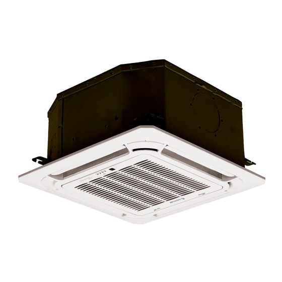
- Page 1 SYSVRF CASSETTE MINI Cassette 600x600 VRF indoor unit INSTALLATION MANUAL...
-
Page 2: Table Of Contents
Install according to this installation instructions strictly. CONTENTS PAGE If installation is defective, it can cause water leakage, electrical shock or fire. PRECAUTIONS......................1 INSTALLATION INFORMATION................2 When installing the unit in a small room, take measures against to keep refrigerant concentration from exceeding INSPECTING AND HANDLING THE UNIT............2 allowable safety limits in the event of refrigerant leakage. -
Page 3: Installation Information
Carry out the specified installation work after taking into 2. INSTALLATION INFORMATION 2. INSTALLATION INFORMATION account strong winds, typhoons or earthquakes. Improper installation work may result in the equipment falling and causing accidents. To install properly, please read this "installation manual" at If the refrigerant leaks during installation, ventilate the first. -
Page 4: Attached Fittings
4. ATTACHED FITTINGS Please check whether the following fittings are of full scope. If there are some spare fittings, please restore them carefully. Four-way Four-way NAME SHAPE Cassette (compact) Cassette 1. Installation paper board INSTALLATION FITTINGS 2. Bolt M6 3. Soundproof / insulation sheath Tubing &... -
Page 5: Indoor Unit Installation
5. INDOOR UNIT INSTALLATION Please adjust the hexangular nuts on the four installation hooks evenly, to ensure the balance of the body. 5.1 Installation place If the drainpipe is awry, leakage will be caused by the malfunction of the water-level switch. (Refer to Fig.5-1,Fig.5-2,Fig.5-3 for specification.) Adjust the position to ensure the gaps between the body and the four sides of ceiling are even. - Page 6 Drain side NOTE All the pictures in this manual are for explanation purpose only. They may be slightly different from the conditioner purchased(depend model).The actual shape shall prevail. 5.3 Install The Panel CAUTION 545(Hook-location) 570(Body) Never put the panel face down on floor or against the (Unit: mm) 647(Panel) wall, or on uneven surfaces.
-
Page 7: Install The Connecting Pipe
6. INSTALL THE CONNECTING PIPE Install the panel on the main body with bolt (M5×16) and washer. (Refer to Fig.5-11 ) Adjust the four panel hook screws to keep the panel Check whether the height drop between the indoor unit and horizontal, and screw them up to the ceiling evenly. -
Page 8: Refrigerant Pipe Connection
90 ° ± 4 Use refrigerant oil R0.4~0.8 Fig.7-2 Fig.6-1 Table.7-1 Bend the pipe with thumb A(mm) Outside diameter Fig.6-2 Φ6.4mm 12.4 12.0 Φ9.5mm Φ12.7mm 15.8 15.4 Make the ends 19.0 18.6 straight Φ15.9mm Fig.6-3 Φ19.1mm 23.3 22.9 Locate The Pipe Fasten the nut ●... -
Page 9: Connect The Drain Pipe
7.2 Check The Leakage The necessary filling amount of refrigerant ● Check all the joints with the leak detector or soap water. (See Refrigerant volume to be added is calculated according to Fig.7-6 as a reference illustration) outdoor unit installation manual .Be sure to add refrigerant measuring by a scale. -
Page 10: Wiring
5) When connecting drainpipe, don’t drag the pipe that would pull 8.2 Drainage Test the main unit. For this, please arrange bearing points every 0.8 to 1.0 meter to avoid pipe be bended (See Fig.8-1 b). Check whether the drainpipe is unhindered 6) When connect a lengthen drainpipe, apply protective tube to New built house should have this test done before paving wrap its indoor parts for ensuring the lengthen part connected... -
Page 11: Control
Table.9-1 Terminal board diagram Please refer to the indoor unit wiring diagram for the wiring. Model(W) 1500~5600 Phase 1-Phase Power 220-240~50Hz NOTE Frequency and volt 208-230~60Hz The air-conditioners can connect with Central Control Circuit breaker/fuse (A) 15/15 Monitor (CCM). Before operation, please wiring correctly Indoor unit power wiring (mm and set system address and network address of indoor 3×2.0... -
Page 12: Network Address Set
ENC1 Dial switch Horsepower setting Network address set Code Capacity(Horsepower) ● Network address is set by communication of indoor and Note: The horsepower 1500W(0.6HP) outdoor unit; the address is the same as indoor address, there has been set before is no need to set separately. leaving the factory , 2200W(0.8HP) The central control of indoor units can be done on outdoor... -
Page 13: Trouble Shooting
definition 12. TEST OPERATION 1 means auto wind under auto mode The test operation must be carried out after the entire installation has been completed. 0 means auto wind under non auto mode Please confirm the following points before the test operation: ●... - Page 14 SYSVRF CASSETTE MINI_IM EN - April 2014 MDV11I-025EW)
Need help?
Do you have a question about the SYSVRF CASSETTE MINI and is the answer not in the manual?
Questions and answers