SystemAir SYSVRF2 CASSETTE MINI Installation Manual
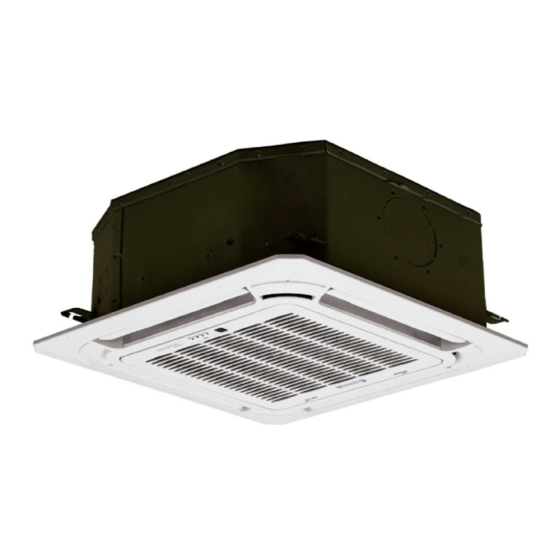
Cassette 600x600 vrf indoor unit
Hide thumbs
Also See for SYSVRF2 CASSETTE MINI:
- Installation manual (16 pages) ,
- Owner's manual (18 pages) ,
- Owner's manual (11 pages)
Table of Contents
Advertisement
Quick Links
Advertisement
Table of Contents

Related Manuals for SystemAir SYSVRF2 CASSETTE MINI


Summary of Contents for SystemAir SYSVRF2 CASSETTE MINI
- Page 1 SYSVRF2 CASSETTE MINI Cassette 600x600 VRF indoor unit INSTALLATION MANUAL...
-
Page 2: Table Of Contents
Only use the attached accessories parts and specified CONTENTS PAGE parts for installation. Otherwise, it will cause the unit to fall and may also cause water PRECAUTIONS..................1 leaks, electrics shocks, or fire. INSTALLATION INFORMATION..............2 Install in a strong location which that can bear the unit' s INSPECTING AND HANDLING THE UNIT..........2 weight. -
Page 3: Installation Information
2. INSTALLATION INFORMATION Consider environmental factors, such as typhoons and earthquakes, during installation. Improper installation may result in the equipment falling. If refrigerant leakage occurs, ventilate the area immediately. To install the unit properly, please read this Installation Toxic gas may be produced if the refrigerant comes into Manual. -
Page 4: Attached Fittings
4. ATTACHED FITTINGS Please check whether all the following fittings have been included. If there are spare fittings, please store them carefully. Table 4-1 Four-way Name Shape Cassette (compact) Installation Fittings 1. Installation paper board Tubing & Fittings 2. Soundproof / insulation sheath 3. -
Page 5: Indoor Unit Installation
5. INDOOR UNIT INSTALLATION Use the transparent hose filled with water to check the lever of the main body from the four sides or diagonal line direction. 5.1 Installation place The lever indicator can check the lever from the four sides of the main body. - Page 6 647(Panel) Unit: mm NOTE 570(Body) 545(Hook-location) All illustrations in this manual are for reference only. They may be slightly different from the air conditioner you purchased (depend on model). The actual shape should be followed. 5.3 Install The Panel CAUTION Never put the panel face down on floor or against the wall, Fig.5-3 Drainage side...
- Page 7 Keep fastening the screws under the panel hooks until the Modify the height of the indoor unit through the openings thickness of sealing sponges 1&2 between the body and on the panel's four corners, if lifting the indoor unit and the drainage pipe is not influenced (Refer to Fig.5-14-right ).
- Page 8 Panel Installation Instruction 5.3 Connect the wiring between the indoor unit and the panel. Sleeve Tighten belt 5.1 Fix the panel to the indoor unit and open the grill, as shown below. 5.4 Move the sleeve to the middle of the wirings and use the tighten belt to tie the sleeve ends tightly.
-
Page 9: Install The Connection Pipe
6. INSTALL THE CONNECTION PIPE Use frozen oil Check whether the height drop between the indoor unit and outdoor unit, the length of the refrigerant pipe, and the number of the bends meet the following requirements: Fig.6-1 ● The max height drop and length of refrigerant pipe depend on the outdoor unit. - Page 10 90 ° ± 4 The necessary filling amount of refrigerant ● The refrigerant volume to be added is calculated according to outdoor unit installation manual. Add refrigerant by measuring it on a scale. L: The length of the pipe R0.4~0.8 Fig.7-2 ●...
-
Page 11: Connect The Drainage Pipe
5) When connecting the drainage pipe, do not drag the pipe and 7.2 Check The Leakage thus pull the main unit. To do so, arrange bearing points every 800 to 1000 mm to avoid bending the pipe (Refer to Fig.8-1 b). Check all the joints with the leak detector or soapy water. -
Page 12: Electrical Connection
8.2 Drainage Test power wire connection Check that the drainage pipe is unhindered The indoor unit and outdoor unit should use separate power supplies, independent leakage protectors and an all-pole Newly built house should be tested before decorating the disconnection device. ceiling. - Page 13 Table 9-2 Thickness of main power wire, switch capacities Minimum wire thickness Switch(A) Breaker [AWG]) Total capacit y Breaker for current leakage for wiring of Indoor units Main Power Wire Ground wire Capacity Fuse < 10A or 1.3[16] 15A 10mA 0.1sec. or less 1.3[16] singel unit 15A~10A...
-
Page 14: Control Operation
Example of communication wiring of the CONTROL OPERATION heat pump system 10.1 Hoursepower Outdoor unit Centralized controller Hoursepower code PO WER_S P Q E ENC1 Base on different purposes to setting the switch cords on PC panel of indoor electrical control box. Once finish the setting, please cut off the main power, and then input power again, otherwise, setting function could not work. - Page 15 10.3 Main board Code designation SW6 definition SW1 definition 00 means the temp. compensation value is 6°C in heat mode (default) 0 means the cooling mode temperature S W 1 compensation is 0°C (default) 01 means the temp. compensation 1 means the cooling mode temperature value is 2°C in heat mode compensation is 2°C 10 means the temp.
-
Page 16: Test Operation
11 . TEST OPERATION According to the user’s requirements, install the remote controller frame where the remote controller’s signal can reach the indoor unit smoothly. Test operation CAUTION ● Set the air conditioner in "COOLING" mode with the remote controller. Then check the following points according to the The protection function will delay the startup of compressor for "Owner’s Manual". - Page 17 MD17I-016AW 16126000002987 V1.3...
Need help?
Do you have a question about the SYSVRF2 CASSETTE MINI and is the answer not in the manual?
Questions and answers