Table of Contents
Advertisement
Quick Links
Download this manual
See also:
Service Manual
OPERATOR'S MANUAL
D500
Defibrillator/Monitor
EU representative
OBELIS S.A
Bd. Général Wahis, 53, 1030 Brussels, Belgium
Local distributor
Manufacturer
Mediana Co., Ltd.
132, Donghwagongdan-ro, Munmak-eup,
Wonju-si, Gangwon-do, Korea
Tel: (82) 2 542 3375 (82) 33 742 5400
Fax: (82) 2 542 7447 (82) 33 742 5483
Part Number: A7226-6
Revised Date: 2017-01
Copyright © 2017 All rights reserved.
Advertisement
Table of Contents
Troubleshooting

Related Manuals for Mediana D500


Summary of Contents for Mediana D500
- Page 1 EU representative OBELIS S.A Bd. Général Wahis, 53, 1030 Brussels, Belgium Local distributor Manufacturer Mediana Co., Ltd. 132, Donghwagongdan-ro, Munmak-eup, Wonju-si, Gangwon-do, Korea Tel: (82) 2 542 3375 (82) 33 742 5400 Fax: (82) 2 542 7447 (82) 33 742 5483...
- Page 2 The D500 conforms to the EMC standard IEC60601-1-2. Note that mobile phones should not be used in the vicinity of the D500. Note, however, any device not complying to the EMC standard that is used with the D500 renders the D500 as non-compliable to the EMC standard.
-
Page 3: Table Of Contents
General Safety Information ........................7 Warning ..............................7 Cautions .............................. 12 INTRODUCTION ............................13 Intended Use for the D500 ........................13 Indications for Use ..........................13 About This Manual ..........................15 Identifying the D500 Configurations ....................15 DESCRIPTION OF THE DEFIBRILLATOR/MONITOR ................17 Front Panel Components........................ - Page 4 MANUAL MODE ............................79 General ..............................79 Preparing for Defibrillation ........................80 Operating the Manual Mode of defibrillator/monitor ................80 Defibrillating (async mode) ........................81 Synchronized Cardioversion (sync mode) ..................81 Description of Manual Mode Menu Functions ..................83 MONITOR MODE ............................89 General ..............................
- Page 5 EVENT ............................... 141 General .............................. 141 Event Data List Display ........................141 Event Review Display ........................142 12 Lead Record Display ........................143 ID# ..............................143 REAL-TIME DATA ............................ 145 General .............................. 145 Real-time data menu ......................... 145 Real-time data recording ........................146 Header recording ..........................
- Page 6 Figures Figure 1. Front panel components ......................17 Figure 2. Top panel components ......................... 19 Figure 3. Rear panel components ....................... 20 Figure 4. Left panel components ......................... 21 Figure 5. Right panel components ......................21 Figure 6. Displays ............................23 Figure 7.
- Page 7 Figure 57. Connection for sidestream ....................... 126 Figure 58. EtCO Display .......................... 127 Figure 59. EtCO Waveform Display ......................127 Figure 60. EtCO Menu Display ........................ 127 Figure 61. Temperature Display ........................ 130 Figure 62. Temperature Menu Display ...................... 130 Figure 63.
- Page 8 Tables Table 1. The defibrillator/monitor controls ....................18 Table 2. The defibrillator/monitor controls on paddle .................. 19 Table 3. Panel and Label Symbols ......................22 Table 4. Display Symbols ..........................24 Table 5. Display Colors Factory Defaults ....................25 Table 6. Standard Accessories ........................28 Table 7.
-
Page 9: Safety Information
SAFETY INFORMATION General Safety Information This section contains important safety information related to general use of the D500 defibrillator/monitor. Other important safety information appears throughout the manual. The D500 defibrillator/monitor will be referred to as the defibrillator/monitor throughout this manual. - Page 10 Do not open cover or disassemble this defibrillator/monitor. Doing so could cause electric shock or fire. It is prohibited by law to modify the defibrillator/monitor without authorization. Do not use power source other than the specified voltage, (100- 240V~50/60Hz) as this may cause fire or electric shock. Pre-use inspection and preventive maintenance must be performed for safe use.
- Page 11 wall socket. Place an “Out of Order” sign on the defibrillator/monitor and do not use it. Have the defibrillator/monitor serviced to make sure that no hazard exists. Do not connect more than one patient to the defibrillator/monitor. Do not connect more than one defibrillator/monitor to a patient. The defibrillator/monitor is a prescription device and is to be operated by qualified personnel only.
- Page 12 clean the paddle electrode surfaces, handles, and storage area after defibrillation. A gel pathway on the skin between the standard paddles will cause defibrillating energy to arc between paddles and delivery energy away from the heart muscle. Do not allow conductive gel (wet or dry) to become continuous between paddle sites.
- Page 13 AC power according to EN 60601-1. If in doubt, disconnect the patient from the defibrillator before using the system connector. Only use Mediana recommended data transmission cables. For more information, contact Mediana Technical Support. The defibrillator/monitor delivers up to 360 joules of electrical energy.
-
Page 14: Cautions
IEC 60601-1-1 and the electromagnetic compatibility system standard IEC60601-1-2. doubt, consult Mediana Technical Support Representative Where the integrity of the external protective conductor in the installation or its arrangement is in doubt, equipment shall be operated from its internal electrical power source. -
Page 15: Introduction
Intended Use for the D500 The defibrillator/monitor is intended for use by trained medical technician, doctor, nurse or medical specialist in outdoor and indoor emergency care settings including air and ground ambulances within the environmental conditions specified. - Page 16 Indications Contraindications prevent tachycardia. contraindicated contraindicated for use on neonates. Electrocardiography The 12-lead electrocardiogram No known contraindications is used to identify, diagnose and treat patients with cardiac disorders and is useful in the early detection. Noninvasive Blood Noninvasive blood pressure Noninvasive Blood Pressure is Pressure monitoring...
-
Page 17: About This Manual
Identifying the D500 Configurations The following table identifies D500 defibrillator/monitor configurations and how they are indicated. The reference number and serial number are located on the back of the product. All information in this manual, including the illustrations, is based on a device configured... - Page 18 This page is intentionally left blank.
-
Page 19: Description Of The Defibrillator/Monitor
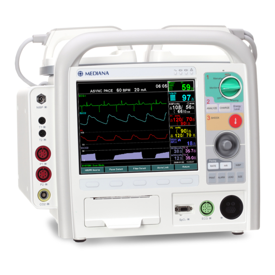
DESCRIPTION OF THE DEFIBRILLATOR/MONITOR Front Panel Components 13 - 16 19 - 21 24 - 25 26 - 30 Figure 1. Front panel components Paddle NIBP connector Mode select knob ANALYZE button Temperature1 connector CHARGE button Temperature2 connector Energy Level button IBP1 connector SHOCK button IBP2 connector... -
Page 20: Table 1. The Defibrillator/Monitor Controls
Table 1. The defibrillator/monitor controls Symbols Description Mode select knob selects five modes of operation. (Pacing, Manual, Monitor, OFF and AED) ANALYZE button analyzes the patient’s ECG to determine whether or not to deliver a shock. CHARGE button charges to the desired energy level automatically. Energy Level button selects the defibrillation energy level. -
Page 21: Top Panel Components
Top Panel Components Figure 2. Top panel components Paddle 4 SHOCK button Energy level button 5 CHARGE button REC button Table 2. The defibrillator/monitor controls on paddle Symbols Description CHARGE button charges to the desired energy level automatically. Energy Level button selects the defibrillation energy level. -
Page 22: Rear Panel Components
Rear Panel Components Figure 3. Rear panel components SMPS/battery push button 5 AC power supply (SMPS) DC input connector 6 Speaker AC power inlet 7 Li-ion battery GND terminal... -
Page 23: Left Panel Components
Left Panel Components 1 Side Option Case Figure 4. Left panel components Right Panel Components 1 Wireless(3G, Wi-Fi) module 2 USB/SD Card Slot Figure 5. Right panel components... -
Page 24: Table 3. Panel And Label Symbols
Table 3. Panel and Label Symbols Symbols Description Symbols Description AC indicator Dust and water resistance Direct current CE mark Battery charging status Prescription only device indicator Service indicator Follow instructions for use Type BF- Defibrillator Proof Separate Collection Type CF- Defibrillator Proof EU representative NIBP connector Manufacturer... -
Page 25: Displays
Displays 3 4 5 Figure 6. Displays Shock count number/icon Title of waveform parameter Defibrillator message area Waveform area Battery status icon Waveform Elapsed time (Power on) Alarm/Informative message area Wi-Fi/3G icon Numerical area Title of numeric area Date/Time ECG waveform message area Soft key menu... -
Page 26: Figure 59. Etco
Table 4. Display Symbols Symbols Description Symbols Description ECG source: Paddle Temperature unit: Celsius Temperature unit: ECG source: Lead l Fahrenheit ECG source: Lead ll unit or EtCO unit: % ECG source: Lead lll Respiration Icon NIBP or IBP or EtCO unit: ECG source: Lead aVL mmHg... -
Page 27: Table 5. Display Colors Factory Defaults
Table 5. Display Colors Factory Defaults Function Color ECG Waveform Green Waveform Cyan Respiration Waveform Light Blue EtCO Waveform Light Purple Green NIBP White Cyan Respiration Rate Light Blue EtCO Light Purple Temperature1 Pink Temperature2 Pink IBP 1 IBP 2 Yellow General background Black... - Page 28 This page is intentionally left blank.
-
Page 29: Setting Up The Defibrillator/Monitor
Unpacking and Inspection The defibrillator/monitor is shipped in one carton. Examine the carton carefully for evidence of damage. Contact Mediana Technical Support Representative immediately if any damage is discovered. Refer to the Maintenance section for instructions on returning damaged items. -
Page 30: List Of Components
List of Components The following items are standard in the package. Table 6. Standard Accessories Items D500 defibrillator/monitor Operator’s manual AC power cord Printer paper Defibrillation pads for adult Defibrillation pads for pediatric Pads extension cable ECG 3 leads cable (SNAP) -
Page 31: Table 7. Optional Accessories
Optional items may be ordered if needed. Contact your local supplier for pricing and ordering information. Table 7. Optional Accessories Items Paddle Defibrillation / external pacing pads for adult Defibrillation / external pacing pads for pediatric NIBP cuff for neonate NIBP cuff hose for neonate ECG 3 leads cable (GRAB) ECG 5 leads cable (SNAP) -
Page 32: Power Cable Connections
Power Cable Connections Do not connect to an electrical outlet controlled by a wall switch or dimmer because the defibrillator/monitor may be accidentally turned off. If the integrity of the AC power source is in doubt, the defibrillator/monitor must be operated from its internal battery. AC Power Make sure that the AC outlet is properly grounded and supplies the specified voltage and frequency (100-240V~ 50/60 Hz). -
Page 33: Measurement Cable Connections
Measurement Cable Connections For best product performance and measurement accuracy, use only accessories supplied or recommended by Mediana. Use accessories according to the manufacturer’s directions for use and your facility’s standards. Use only accessories that have passed the recommended biocompatibility testing in compliance with ISO10993-1. - Page 34 ECG Cables and Leads 1. Connect an ECG cable to the ECG connector making sure that the connector arrow is pointing panel (see Figure 1) Defibrillator Paddle and Pads 1. Connect a paddle or pads to paddle / pads connector on the defibrillator/monitor’s front panel.
-
Page 35: Battery Operation
Be careful not to short the battery terminals because this could result in a fire hazard. Mediana has no information regarding the performance or effectiveness of its Mediana defibrillator/monitors if other manufacturers’ batteries or battery chargers are used. Using other manufacturers’ batteries or battery chargers may cause the defibrillator/monitor to perform improperly and invalidate the safety agency certifications. -
Page 36: Operating The Defibrillator/Monitor On Battery Power
Operating the defibrillator/monitor on Battery Power The defibrillator/monitor has the rechargeable battery that can be used to power the defibrillator/monitor when AC power source or external DC-DC adaptor is not available. The battery status icon appears on the screen when the defibrillator/monitor is on battery power. -
Page 37: Battery Status Indication
Battery Status Indication When operating on batteries, the battery status icon in the lower part of the display indicates the battery charge condition. See Table 9. Table 9. The defibrillator/monitor Battery Status Icon Battery Status Icons Battery Status Icon Color Green (normal condition) Yellow (low battery) Red (critically low battery) - Page 38 This page is intentionally left blank.
-
Page 39: Using The Defibrillator/Monitor
USING THE DEFIBRILLATOR/MONITOR Each time the defibrillator/monitor is used, check alarm limits to make sure that they are appropriate for the patient being monitored. If different alarm presets are used for the same or similar equipment in any single area, e.g. an intensive care unit or cardiac operating room, a potential hazard can exist. -
Page 40: Turning On And Off The Defibrillator/Monitor
Only use thumbs to depress the paddle SHOCK button. Failure to do so could result in the inadvertent depression of the energy select buttons, causing the defibrillator/monitor to disarm itself. Do not discharge the defibrillator/monitor except as indicated in the instructions. -
Page 41: Setting Date And Time
Setting Date and Time You may set the date and time displayed on the screen and printed on the reports. 1. Rotate the Multi function knob to highlight Date/Time, and then press the Multi function knob to select Date/Time Menu. Figure 11. -
Page 42: Continued Use
Continued use This defibrillator/monitor retains the previous settings when the defibrillator/monitor is turned off for less than 10 seconds. And if the defibrillator/monitor was not turned off and less than 10 minutes have elapsed since the operation mode was last used, the defibrillator/monitor retains the previous settings of last operation mode. -
Page 43: Figure 13. Normal Screen (4 Waveform, Defibrillation Mode, Full Option)
4-ch Wave Screen: ECG + SpO + ABP + EtCO Figure 13. Normal Screen (4 waveform, Defibrillation mode, Full option) Large Numeric Screen Figure 14. Large Numeric Screen (2 waveform, Monitor mode, Full option) -
Page 44: Figure 15. Black-White Screen (4 Waveform, Defibrillation Mode, Full Option)
Black-white Invert Screen (Mono-color screen) Figure 15. Black-white Screen (4 waveform, Defibrillation mode, Full option) -
Page 45: Alarms And Limits
ALARMS AND LIMITS Each time the defibrillator/monitor is used, check alarm limits to make sure that they are appropriate for the patient being monitored. If different alarm presets are used for the same or similar equipment in any single area, e.g. an intensive care unit or cardiac operating room, a potential hazard can exist. -
Page 46: Alarm Priority And Messages
Figure 16. Volume Menu Display Alarm Priority and Messages There are three possible priorities for visual and audible alarms: High, Medium, and Low. The high, medium, low priority messages and informative messages are displayed in the alarm/informative message area and the defibrillator messages are displayed in the defibrillator message area. -
Page 47: Table 12. Medium Priority Alarm
Medium Priority Medium priority alarm indicates that prompt operator response is required. Table 12. Medium Priority Alarm Parameter Condition Messages High Heart Rate/Pulse Rate limits High Heart Rate/Pulse Rate limits violated violated HR/PR Low Heart Rate/Pulse Rate limits Low Heart Rate/Pulse Rate limits violated violated ECG Signal Saturation ECG Signal Saturation... -
Page 48: Figure 51. Spo
Low Priority Low priority alarm indicates that operator awareness is required. Table 13. Low Priority Alarm Parameter Condition Messages ECG Leads Off ECG : Leads off Chest Lead off ECG : Chest lead off Temperature Probe Disconnect TEMP1 : Probe disconnect TEMP2 : Probe disconnect Temp Temperature –... -
Page 49: Table 14. Informative Messages
Informative Messages Informative messages indicate a system condition that needs to be corrected. Table 14. Informative Messages Condition Messages ECG offset control ECG: Signal calibration Pulse search : Pulse search Motion interference : Motion interference IBP No zero reading {label}: No zero reading (ex. - Page 50 Condition Messages Analyzing ECG Analyzing heart rhythm (Voice prompt: Analyzing heart rhythm. Do not touch the patient.) Do not touch the patient Do not touch the patient No Shock Advised No Shock Advised (Voice prompt: Non Shock advised.) Shock Advised Shock Advised (Voice prompt: Shock advised.) Press Shock button...
-
Page 51: Visual Alarm Indication
Visual Alarm Indication Table 16. Visual Alarm Characteristics Alarm Category Color Flashing Period Duty Cycle High priority 700ms (about 1.43Hz) 57% (On: 400ms / Off: 300ms) Medium priority Yellow 2000ms (about 0.5Hz) 60% (On: 1200ms / Off: 800ms) Low priority Yellow 100% (Always On) When a high priority alarm is activated, a non-flashing alarm message is displayed. -
Page 52: Changing Alarm Limits
Changing Alarm Limits Each time the defibrillator/monitor is used, check alarm limits to make sure that they are appropriate for the patient being monitored. If different alarm presets are used for the same or similar equipment in any single area, e.g. an intensive care unit or cardiac operating room, a potential hazard can exist. -
Page 53: Table 18. Alarm Limits Ranges
Alarm Limits Ranges Table 18 describes the possible alarm limits. The defibrillator/monitor is shipped with factory default settings. Note: Authorized personnel can define the way to save the power default. The detailed information is described in the service manual. Table 18. Alarm Limits Ranges Parameters Upper Limit, Default Lower Limit, Default... -
Page 54: Audio Paused And Off
Parameters Upper Limit, Default Lower Limit, Default Resolution (-6.0 ~ 40.0 kPa, 12.0 kPa) (-6.7 ~ 39.3 kPa, 3.7 kPa) (0.6 or 0.7 kPa) P2 Diastolic (mmHg, kPa) -45 ~ 300 mmHg, 70 mmHg -50 ~ 295 mmHg, 40 mmHg 5 mmHg Adult/Pediatric (-6.0 ~ 40.0 kPa, 9.3 kPa) - Page 55 To off an audio: 1. To initiate an audible alarm off, press the Alarm button and hold it for at least 2 seconds. 2. To cancel an audible alarm off condition, press the Alarm button for 2 seconds again. This action disables audible alarms for a user-defined audio off period (3 min, 5 min, 10 min or Indefinite) selected via the Service menu.
- Page 56 This page is intentionally left blank.
-
Page 57: Ecg Monitoring
ECG MONITORING For best product performance and measurement accuracy, use only accessories supplied or recommended by Mediana. Use accessories according to the manufacturer’s directions for use and your facility’s standards. It may cause burns to the patients or defibrillator/monitor failure to use of pacing/defibrillation pads or adapters from sources other than Mediana. -
Page 58: General
"Check ECG Leads & Electrodes" alarm. Refer to the Specification section. Setup Connections Note: Mediana recommends the use of silver/silver chloride electrodes (Ag/AgCl). When dissimilar metals are used for different electrodes, the electrodes may be subject to large offset potentials due to polarization, which may be severe enough to prevent obtaining an ECG trace. -
Page 59: Figure 19. 5 Electrode Placement
Figure 19. 5 Electrode Placement Note: One of 5-1 to 5-6 Lead electrode placement sites for the fifth lead. 2. Connect the ECG lead. 3. Connect the ECG lead to the ECG connector on the defibrillator/monitor’s front panel. 4. Attach the leads to the electrodes, and then apply the electrodes to the patient, using the color-code guide in Table 17. -
Page 60: 12-Lead Ecg
12-lead ECG Using previously unpackaged electrodes or electrodes past the Use by date may impair ECG signal quality. Remove electrodes from a sealed package immediately before use and follow the procedure for applying the electrodes. Computerized ECG interpretive statements should not be used withholds or prescribes patient treatment without review of the ECG data by qualified medical personnel. - Page 61 QRS typing Thereafter, the various QRS complexes are typed according to their morphology. An iterative process is used. Effectively, the first complex in lead I is compared with the second using first differences of each cycle. The comparison takes the form of moving one beat over the other and when the difference is minimal, optimal alignment is present.
-
Page 62: Figure 20. Varying Choice Of Baselines
Wave Measurement From the 12 average beats, a single combined function is formed and a provisional overall QRS onset and termination is determined by thresholding techniques. The provisional onset and termination are then used as starting points for a search for QRS onset and termination within each individual lead. -
Page 63: Figure 23. Definitions For Qrs End / St Junction
QRS Components Within the QRS complex, the amplitude and duration of the various Q, R, S, R’ waves are then measured. In keeping with the CSE recommendations, the minimum wave acceptable has to have a duration >8 ms and an amplitude >20 V. With respect to global QRS duration, the Glasgow program measures QRS duration from the global QRS onset to the global QRS termination. -
Page 64: Preparing The 12 Lead
Interval Measurement With respect to intervals, the global QT interval is measured from the global QRS onset to the global T end. On the other hand, because the P onset is taken as being simultaneous in all 12 leads, the global PR interval measurement is from the P onset to the global QRS onset. -
Page 65: Calculation Feature
Calculation Feature Figure 25. Measurement Reference Figure 25 shows the parameters obtained in ECG waveform to analyze the ECG. Overall P onset, P offset, QRS onset, QRS offset and T termination are determined from all 12 leads. Individual lead wave amplitudes are then obtained. P+, P-, Q, R, S, R’, S’, T+ and T- amplitudes are measured with respect to a horizontal line through the lead QRS onset. -
Page 66: Table 22. Measurement Matrix
HYPERTROPHY LEFT VENTRICULAR HYPERTROPHY RIGHT VENTRICULAR HYPERTROPHY BIVENTRICULAR HYPERTROPHY Results on ST And T Wave Analysis Results on ST and T wave analysis shows diagnosis results of ST and T waveform and measurement values. MYOCARDIAL INFARCTION INFERIOR INFARCTION LATERAL INFARCTION ANTEROSEPTAL INFARCTION ANTERIOR INFARCTION... -
Page 67: Figure 26. 12-Lead Ecg Preview Screen
Measurement Meaning STAMP ST wave amplitude in microvolts. 1/8STT Amplitude in microvolts at a point which is 1/8 of the ST-T interval. 2/8STT Amplitude in microvolts at a point which is 2/8 of the ST-T interval. 3/8STT Amplitude in microvolts at a point which is 3/8 of the ST-T interval. -
Page 68: Description Of Hr/Pr Menu Functions
Description of HR/PR Menu Functions The calculated Heart Rate/Pulse Rate may be derived from different sources (ECG, , NIBP or IBP) as shown by the icon in the HR/PR numerical area. HR/PR icon HR/PR unit HR/PR source icon HR/PR value Pacer pulse detection icon Bell icon ECG size... -
Page 69: Hr/Pr Source
HR/PR Source You may select Auto, HR, PR to decide the source of the heart rate or pulse rate. The HR/PR tone volume can be adjusted in the Setup menu. Auto If you select Auto, the defibrillator/monitor automatically derives the heart rate or pulse rate from one of the monitoring parameters in this order of priority: ECG, IBP, SpO NIBP. - Page 70 This page is intentionally left blank.
-
Page 71: Aed(Automated External Defibrillator) Mode
AED(Automated External Defibrillator) MODE The defibrillator/monitor will only administer a shock if it is needed. A voice prompt will tell you when to press the SHOCK button to administer defibrillation therapy. The defibrillator/monitor should not be used on someone who is responsive when shaken or breathing normally. - Page 72 General Defibrillation therapy is the definitive method for termination of a variety of potentially fatal arrhythmias. The defibrillator/monitor’s Automated External Defibrillation (AED) Mode is designed to guide you through standard treatment algorithms for cardiac arrest. The defibrillator/monitor provides therapy through the application of a brief biphasic pulse of electricity to the cardiac muscle.
- Page 73 Preparing for Defibrillation The AED algorithm is not designed to handle erratic spiking problems caused by a properly or improperly functioning pacemaker. In patients with cardiac pacemakers, the defibrillator/monitor may have reduced sensitivity and not detect all shockable rhythms. 1. Confirm that the patient is: ...
-
Page 74: 2010 Aha Guidelines For Cpr And Ecc
2010 AHA Guidelines for CPR and ECC The 2010 AHA Guidelines for CPR and ECC are based on the most current and comprehensive review of resuscitation literature ever published, the 2010 ILCOR International Consensus on CPR and ECC Science with Treatment Recommendations. Bystanders, first responders and healthcare providers all play key roles in providing CPR for victims of cardiac arrest. -
Page 75: Cpr Guidelines 2010
CPR Guidelines 2010 Person not responsive? No signs of life? Address person and shake on shoulder! Perform the CPR Engage other people to help you and alternate CPR! Call for help, get AED Open the airway. Check for breathing! Note: “Look, listen and feel” is removed from the CPR sequence for assessment of breathing after opening the airway in 2010 guidelines. - Page 76 Using AED Mode 1. Turn on the AED Mode of defibrillator/monitor by rotating the Mode select knob. 2. Verify the AED Mode of defibrillator/monitor is activated normally and follow audio guidance and STEP icon. Note: It will take about 4 seconds to initialize AED mode. STEP 1 Check for response.
- Page 77 STEP 6 Press the SHOCK button now. Shock delivered. STEP 7 It is safe to touch the patient. Begin CPR [Beep] or If needed, Begin CPR [Beep] Give two breaths. Stop CPR. Note: If you hear following voice while the AED Mode of defibrillator/monitor is analyzing you should perform the following actions: ...
-
Page 78: Aha 2010 Configuration
At least more than 100 beats per minutes is the recommended rate to perform compressions under AHA 2010 guidelines. Note: Your Mediana dealer will have trained you in the particular SCA treatment protocol you have chosen. In all cases follow the voice prompts and visual instructions given by the AED mode. -
Page 79: Figure 31. Patient Info: Id Menu
Table 24. AED Mode Menu Level1 Level 2 Menu Level 3 Menu Level 4 Menu Menu or Response or Response or Response Patient Info Confirm Name Confirm Confirm Gender Male Female Event Data review Print records Name Gender Real-time Print data Download Return... - Page 80 This page is intentionally left blank.
-
Page 81: Manual Mode
15 and 250 ohm. Whenever possible, Mediana recommended that user performs synchronized defibrillation (cardioversion) procedures while directly monitoring the patient through the defibrillator’s electrodes or lead inputs. -
Page 82: Preparing For Defibrillation
Preparing for Defibrillation Using adult paddles 1. External paddles are placed on the device. 2. Remove the paddles from the paddle tray by pulling the paddles straight up and out of the paddle tray. 3. Apply conductive matter to the paddle electrodes. Do not distribute conductive matter by rubbing the paddle electrodes together. -
Page 83: Defibrillating (Async Mode)
Defibrillating (async mode) If the device and paddles are prepared for defibrillation, perform the following steps; To select the energy setting, press the Select Energy Level button and rotate the Multi function knob to the desired energy level. Energy choices range from 1 to 200J. - Page 84 To charge the energy, press the CHARGE button. If using external paddles, the CHARGE button on the paddles may be used instead. Note: You may increase or decrease the selected energy at any time during charging or after charging is complete. There are two ways to shock the energy.
-
Page 85: Description Of Manual Mode Menu Functions
Description of Manual Mode Menu Functions Figure 33. Manual Mode Menu Table 25. Manual Mode Menu Level 2 Menu Level 3 Menu Level 4 Menu Level1 Menu or Response or Response or Response 12 Lead Acquire Setup Filter 0.05Hz ~ 40Hz 0.05Hz ~ 150Hz Transmission 12 lead ON... - Page 86 Level 2 Menu Level 3 Menu Level 4 Menu Level1 Menu or Response or Response or Response Print on shock Print on mark Print on BP Print on self-test 12 lead auto printing Analyze auto printing Erase data Erase 12 lead records Erase event records Erase internal memory Waveform...
-
Page 87: Figure 34. Setup Menu
Level 2 Menu Level 3 Menu Level 4 Menu Level1 Menu or Response or Response or Response Confirm Name Confirm Confirm Gender Male Female Event records Data review Print Name Gender Real-time Print data Download Return Sync On/Off 12 Lead Acquire To acquire the 12 lead ECG data from patient, press the Acquire soft key. - Page 88 1. Rotate the Multi function knob to highlight Alarm volume, Beep volume or Button volume. 2. Press the Multi function knob. Levels of Alarm volume, Beep volume or Button volume will appear. 3. Rotate the Multi function knob to select a volume level. 4.
-
Page 89: Figure 35. Alarm Limit Menu
Alarm Limit Figure 35. Alarm Limit Menu Press the Multi function knob to select Alarm limits. The defibrillator/monitor will display all alarm limits that are currently in effect for all monitored parameters. Select the alarm limits to set Patient Info ID, Name, Age or Gender of patients can be entered in this menu. - Page 90 This page is intentionally left blank.
-
Page 91: Monitor Mode
MONITOR MODE General In monitor mode, you can monitor Electrocardiography (ECG) acquired a 3-. 5-, or 10- lead ECG electrodes. Optional monitoring of functional arterial oxygen saturation (SpO respiration (RESP), temperature (TEMP), invasive blood pressure (IBP), noninvasive blood pressure (NIBP), and end tidal CO (EtCO ), invasive blood pressure (IBP) are also available. - Page 92 Level 2 Menu Level 3 Menu Level 4 Menu Level1 Menu or Response or Response or Response ID # Name Gender Setup Volume Alarm Beep Button Charging alarm Voice prompt CPR metronome Pacing alarm Printer Print on alarm Setting Print on charge Print on shock Print on mark Print on BP...
- Page 93 Level 2 Menu Level 3 Menu Level 4 Menu Level1 Menu or Response or Response or Response IBP1 IBP2 EtCO Display Mode Large numeric display Black-white Invert Mode Clinical action list Manual self- test Button test Service menu (Display 3 digit code) Return Alarm Limit ▲...
-
Page 94: Figure 38. Setup Menu
Setup Figure 38. Setup Menu Volume The Volume options allow you to adjust the volume of Alarm, Beep, Button, Charging alarm, Voice prompt, CPR metronome, Pacing alarm. Alarm volume, Charging alarm and Voice prompt can be set at level 1 to 8 and Beep volume, Button volume, CPR metronome and Pacing alarm can be set at level 1 to 7 or Off. -
Page 95: Figure 40. Patient Info: Id Menu
Button test The user can check buttons for proper functioning. It can be performed by ‘Button Test’ function in the Setup Menu. Service Menu Only authorized personnel are allowed to change the Service Menu settings. A 3 digit code is required for access. Refer to the service manual for instructions. Alarm Limit Figure 39. - Page 96 This page is intentionally left blank.
-
Page 97: Pacing Mode
PACING MODE Use sync mode pacing whenever possible. Use Fixed mode pacing when motion artifact or other ECG noise makes R-wave detection unreliable. Observe the patient continuously while the pacemaker is in use. Patient response to pacing therapy (for example, capture threshold) may change over time. -
Page 98: Demand Mode And Fixed Mode
Demand Mode and Fixed Mode The defibrillator/monitor can deliver pace pulses in either Demand mode or Fixed mode. 1. In Demand mode, the defibrillator/monitor only delivers pace pulses when the patient’s heart rate is lower than the selected pacing rate. 2. -
Page 99: Fixed Mode Pacing
When the mA button is pressed, each color of output value is changed and the output value can be modified. The ‘Select mA’ defibrillator message is displayed. Rotate the Multi function knob to the desired output value and then press the Multi function knob to select the desired output value. -
Page 100: Description Of Pacing Mode Menu Functions
Description of Pacing Mode Menu Functions Figure 42. Pacing Mode Menu Table 27. Pacing Mode Menu Level 2 Menu Level 3 Menu Level 4 Menu Level1 Menu or Response or Response or Response Pause Pacing Setup Volume Alarm Beep Button Charging alarm Voice prompt CPR metronome... - Page 101 Level 2 Menu Level 3 Menu Level 4 Menu Level1 Menu or Response or Response or Response Erase internal memory Erase internal memory Waveform Waveform ECG waveform I, II, III, aVL, aVF, aVR, V1, V2, setting V3, V4, V5, V6, Pads waveform Respiration waveform IBP1 waveform...
-
Page 102: Figure 43. Setup Menu
Pause Pacing When the Pause Pacing soft key is pressed, if pacing is operating, pacing will be paused, if pacing is not operating, pacing will be resumed. Setup Figure 43. Setup Menu Volume The Volume options allow you to adjust the volume of Alarm, Beep, Button, Charging alarm, Voice prompt, CPR metronome and Pacing alarm. -
Page 103: Figure 44. Alarm Limit Menu
section. Button Test The user can check buttons for proper functioning. It can be performed by ‘Button Test’ function in the Setup Menu. Service Menu Only authorized personnel are allowed to change the Service Menu settings. A 3digit code is required for access. Refer to the service manual for instructions. Alarm Limit Figure 44. - Page 104 This page is intentionally left blank.
-
Page 105: Nibp Monitoring
NIBP MONITORING For best product performance and measurement accuracy, use only accessories supplied or recommended by Mediana. Use accessories according to the manufacturer’s directions for use and your facility’s standards. Inaccurate measurements may be caused by incorrect cuff application or use. -
Page 106: General
fibrillation, arterial sclerosis, poor perfusion, diabetes, age, pregnancy, pre-eclampsia, renal diseases, patient motion, trembling, and shivering. In the automatic mode, the defibrillator/monitor displays results of the last blood pressure measurement until another measurement starts. If a patient’s condition changes during time interval between... - Page 107 to increase in amplitude with decreasing cuff pressure until they reach a maximum amplitude at which point they begin to decrease with decreasing cuff pressure. The cuff pressure at which the pulse amplitude is the greatest is known as Mean Arterial Pressure (MAP).
- Page 108 Mediana’s measurement technology utilizes a unique deflation technique, Dynamic Linear Deflation. This cuff deflation technique allows the Mediana monitor to measure each small change in the cuff pressure oscillations that directly correspond to the measurement’s systolic, mean and diastolic blood pressure values.
-
Page 109: Setup Connections
defibrillator/monitor but, as described above, determines blood pressure from an uninterrupted changing curve, which means that the oscillometric method is not easily effected by external noise and electrosurgical instruments. Note: This equipment is suitable for use in the presence of electro-surgery. Setup Connections 1. -
Page 110: Description Of Nibp Menu Functions
Table 28. Cuff Size Model Number Arm circumference (cm) Neonate Cuff No.10 3.5 to 6 Cuff No.11 5.0 to 7.5 Cuff No.12 7.5 to 10.5 Cuff No.13 8.5 to 13 Pediatric HEM-CS23 13 to 22 HXA-GCUFF-SSLA 12 to 18 HXA-GCUFF-SLA 17 to 22 Adult HEM-CR23... - Page 111 ▼ MAP Lower Limit Adjust ▲ DIA Upper Limit Adjust ▼ DIA Lower Limit Adjust (Limit Alarm Pause) On, Off Return Note: Initial Inflate Pressures shown above are for Adult patient mode. In order to set alarm limits to Neonatal mode, change Patient type via the Setup Menu. Note: The NIBP unit can only be changed by authorized personnel via the Service Menu.
- Page 112 This page is intentionally left blank.
-
Page 113: Spo Monitoring
For best product performance and measurement accuracy, use only ® accessories manufactured by Nellcor or supplied by Mediana. Use accessories according to the manufacturer’s directions for use and your facility’s standards. Tissue damage can be caused by incorrect application or use of an SpO sensor. -
Page 114: General
flow to the extremities (such as those in severe shock or hypothermia), or in the presence of excessive motion. Failure to apply the sensor properly may reduce the accuracy of the SpO measurement. Inspection the sensor application site at least every two hours for changes in skin quality, correct optical alignment, and proper sensor application. -
Page 115: Theory Of Operation
Theory of Operation The defibrillator/monitor uses pulse oximetry to measure functional oxygen saturation in the blood. Pulse oximetry works by applying a Nellcor™ pulse oximetry sensor to a pulsating arteriolar vascular bed, such as a finger or toe. The sensor contains a dual light source and a photodetector. -
Page 116: Figure 48. Oxyhemoglobin Dissociation Curve
Figure 48. Oxyhemoglobin Dissociation Curve 1 % Saturation Axis 6 Increased pH; Decreased temperature, PCO , and 2,3-DPG 2 PO (mmHg) Axis 7 Decreased pH; Increased temperature, PCO , and 2,3-DPG... -
Page 117: Clinical Studies
Clinical Studies Clinical studied conducted for the Nellcor™ Sensors Overview This appendix contains data from clinical studies conducted for the Nellcor™ sensors used with the defibrillator/monitor. One (1) prospective, controlled hypoxia clinical study was conducted to demonstrate the accuracy of Nellcor™ sensors when used in conjunction with the defibrillator/monitor. The study was performed with healthy volunteers at a single clinical laboratory. -
Page 118: Figure 49. Modified Bland-Altman Plot
Figure 49. Modified Bland-Altman Plot Test Sensor: Avg CO-oximeter value 70-100% SpO Avg CO-oximeter value 70-100% SpO Oximetry board with MAX-A sensor Trendline of MAX-A sensor Oximetry board with MAX-N sensor Trendline of MAX-N sensor Oximetry board with MAX-FAST sensor Trendline of MAX-FAST sensor Adverse Events or Deviations The study was conducted as expected with no adverse events and no deviations from the... -
Page 119: Setup Connections
Refer ® to Table 32, or contact Nellcor or Mediana sales department for ordering information. 1. Select the proper sensor for the patient. 2. Connect the extension cable to the SpO connector on the defibrillator/monitor’s front... -
Page 120: Figure 50. Spo2 Display
Description of SpO Menu Functions icon value Pulse amplitude indicator Bell icon Figure 50. SpO Display waveform icon waveform Figure 51. SpO Waveform Display Pulse Amplitude Indicator The pulse amplitude indicator is the segmented display within the SpO numerical area that shows the relative strength of the detected pulse. -
Page 121: Respiration Monitoring
RESPIRATION MONITORING For best product performance and measurement accuracy, use only accessories supplied or recommended by Mediana. Use accessories according to the manufacturer’s directions for use and your facility’s standards. The defibrillator/monitor does not detect apnea when the respiration signal is measured by trans-thoracic impedance. -
Page 122: Theory Of Operation
Theory of Operation The respiration monitoring is designed to use the variation of this thoracic impedance. The chest contains various materials, ranging from bone to air. Each of these materials has different electrical properties and is located in a different portion of the chest. The materials of the chest vary in electrical resistivity (the amount of electrical resistance between opposite faces of a cube of that material), which is an important determinant of electrical impedance in the body. -
Page 123: Description Of Respiration Menu Functions
Description of Respiration Menu Functions Respiration rate icon 4 Respiration icon Respiration rate source icon 5 Measurement Value Bell icon Figure 53. Respiration Display Respiration waveform icon Respiration waveform Figure 54. Respiration Waveform Display Respiration Respiration Apnea time setting Alarm Limit Return Setting Figure 55. - Page 124 RR Source User can select either Airway or Impedance for source of the respiration rate. If the Auto is selected, the defibrillator/monitor will automatically drive the respiration rate from one of the monitoring parameters in this order of priority; Airway and Impedance. Note: You can select Airway as the source when CO module is installed.
-
Page 125: Capnography Monitoring
CAPNOGRAPHY MONITORING For best product performance and measurement accuracy, use only accessories supplied or recommended by Mediana. Use accessories according to your facility’s standards and the manufacturer’s recommendation. Always refer to the manufacturer’s Directions for Use for instruction about operation, cleaning, and replacement. -
Page 126: General
When using the defibrillator/monitor in high-altitude environments, it is advisable to consider adjusting EtCO alarm settings accordingly. Do not operate the Capnostat sensor when it is wet. Do not immerse the device in water. Do not operate the Capnostat sensor if it appears to have been damage or if it fails to operate properly. -
Page 127: Setup Connections
Setup Connections The defibrillator/monitor has one capnography sensor receptacle which may be used for a mainstream capnography sensor or a sidestream capnography sensor. Note: Capnograpy is not analyzed during unit warm-up however, the capnography does display to indicate that the defibrillator/monitor is working properly. Note: The typical initial warm-up period can take up to two minutes. -
Page 128: Figure 57. Connection For Sidestream
Sidestream Operation Sidestream monitoring uses an external, sidestream sensor that plug into the capnography port on the defibrillator/monitor. Adult, pediatric, or infant sampling lines are then plugged into the sensor receptacle. Respiration can be monitored for intubated or non-intubated patients via an airway adapter, nasal cannula, or nasal/oral cannula using the sidestream function of the module. -
Page 129: Description Of Etco Menu Functions
Description of EtCO Menu Functions EtCO icon EtCO unit EtCO value Bell icon InCO icon InCO unit InCO value Figure 58. EtCO Display EtCO waveform icon EtCO waveform Figure 59. EtCO Waveform Display Figure 60. EtCO Menu Display Table 35. EtCO Menu Menu Level 2 Menu or Response... - Page 130 EtCO When the capno measurement is On, EtCO , InCO and capno waveform measurement are activated. EtCO Setting As the N in the sample gas is replaced by O , the effect is a decrease in IR absorption. This results in a lower than actual measured CO value (CO measured).
-
Page 131: Temperature Monitoring
TEMPERATURE MONITORING For best product performance and measurement accuracy, use only YSI 400 and 700 series temperature probes recommended by Mediana. Use accessories according to the manufacturer’s directions for use and your facility’s standards. General Measurement of patient temperature is accomplished by processing the signal from a probe containing a resistance element whose impedance is temperature dependent. -
Page 132: Description Of Temperature Menu Functions
Description of Temperature Menu Functions Temperature1 icon Temperature1 unit Temperature1 value Bell icon Temperature2 icon Temperature2 unit Temperature2 value Figure 61. Temperature Display Alarm Limit Return Figure 62. Temperature Menu Display Table 37. Temperature Menu Menu Level 2 Menu or Response TEMPERATURE MENU (Alarm Limit) ▲... -
Page 133: Ibp Monitoring
IBP MONITORING Proper measurements may not be possible, If improper zero calibration was performed. If air bubbles are mixed into the patient circuit. If the height of the three-way tap for zero calibration and the right auricle have changed. If the pressure transducer has been dropped or subjected to strong physical shock, check for faults before use. -
Page 134: General
General The invasive blood pressure measurement measures the systolic pressure, mean pressure, diastolic pressure and pulse rate for up to 2 blood pressure line channels using blood pressure transducers, and displays the blood pressure waveform. Theory of Operation The pressure transducer is connected to a pressure line which, by means of a catheter is invasively connected to the patient blood stream. -
Page 135: Description Of Ibp 1 Menu Functions
Description of IBP 1 Menu Functions 1 IBP 1 label icon 4 IBP 1 unit 2 Systolic value 5 Diastolic value 3 Mean arterial pressures value 6 Bell icon Figure 64. IBP 1 Display 1 IBP 1 label icon 2 IBP 1 waveform Figure 65. -
Page 136: Description Of Ibp 2 Menu Functions
Zero Setting When Zero Setting is set to Enter, IBP 1 channel is calibrated. Scale The user-selectable pressure waveform scale allows you to adjust the scale of a pressure waveform. The scale can be selected as 0 to 0 ~ 50mmHg, 0 ~ 100mmHg, 0 ~ 200mmHg, 0 ~ 300mmHg or Auto. -
Page 137: Table 39. Ibp 2 Menu
Table 39. IBP 2 Menu Level 1 Menu Level 2 Menu or Response IBP 2 MENU Zero Setting Enter Scale 0 ~ 50mmHg, 0 ~ 100mmHg, 0 ~ 200mmHg, 0 ~ 300mmHg, Auto Label (Alarm Limit) ▲ SYS Upper Limit Adjust ▼... - Page 138 This page is intentionally left blank.
-
Page 139: Self-Test Function
SELF-TEST FUNCTION General This defibrillator/monitor incorporates a Self-test function. The defibrillator/monitor should be checked at regular intervals so that it will always be ready-to-use for emergency situations. There are three modes: Manual Self-test, Auto Self-test and Button test. Additionally, the external shock test should be performed prior to use. Manual Self-test If the user wants to perform a High-voltage module alive test, Body impedance test, ECG circuit and algorithm test, internal shock test, internal pacing output test, pads/paddle... -
Page 140: Functions To Be Tested In Self-Test
Functions to be tested in Self-test The defibrillator/monitor Self-test performs 11 test steps. Lists and descriptions of the tests are indicated below. Figure 70. Auto Self-test display Table 40. Self-test functions Test Description High-Voltage module To check if the High-Voltage module is operational operational test and available to communicate. -
Page 141: External Shock Test
External shock test The user must verify the ability to deliver defibrillation energy once a week. Figure 71. External shock test 1. Make sure the paddles and the paddle tray are thoroughly clean and there is no residue including the conductive material on electrode surfaces of the paddle and paddle tray. - Page 142 This page is intentionally left blank.
-
Page 143: Event
EVENT General Event data in either graphical or tabular format may be displayed on 3 and 4 waveform display area. 1. Press the Patient Info soft key. 2. Rotate the Multi function knob to Event records on the screen and press the Multi function knob to display. -
Page 144: Event Review Display
Event Review Display Event information in graphical format for ECG data is displayed in a graph. The defibrillator/monitor displays the event information through recent 10sec after and before event occurred. When printing the event information, all the parameters like ECG, SpO NIBP, Temp, EtCO , IBP and Respiration are printed. -
Page 145: 12 Lead Record Display
12 Lead Record Display The 12 lead data is displayed in tabular format as shown in Figure 74. Patient ID, name, age, gender and time are displayed. The newest data appears at the top of tabular events. To scroll the event data list, rotate the Multi function knob when the 12 lead data list is displayed. - Page 146 This page is intentionally left blank.
-
Page 147: Real-Time Data
REAL-TIME DATA General This defibrillator/monitor is designed to print the Real-time data and download to Real- time data in SD card. Real-time data menu List of Real-time data shows a maximum of 18 data in Real-time data menu as shown in Figure 75. -
Page 148: Real-Time Data Recording
Real-time data recording Real-time data contains header(print case, patient info and device info), event messages, waveform, shock information and trend in real time. In order to write by user, the comments, weight, height, device type and operator are left blank. Header recording The defibrillator/monitor prints case, patient info and defibrillator/monitor info in header as shown in Figure 76. -
Page 149: Waveform Recording
Waveform recording Waveform which the event occurred is displayed. Waveform contains ECG, V-FIB, shock and pacing event as shown in Figure 77. Shock information recording Shock info displays the shock event among all events. Shock info contains shock time, number of shock and energy as shown in Figure 77. The time, number of shock and energy is displayed from left to right. - Page 150 This page is intentionally left blank.
-
Page 151: Menu Structure
MENU STRUCTURE MANUAL MODE MENU 12 lead Acquire Setup Filter 0.05Hz ~ 40Hz 0.05Hz ~ 150Hz Return Transmission Return 12 lead ON Patient info Confirm Return Name Confirm Return Confirm Return Gender Male Female Return 12 lead records Print Transmission ID # Return Return... - Page 152 Print on mark Print on BP Print on self-test 12 lead auto printing Analyze auto printing Return Erase data Erase 12 lead records Erase event records Erase internal memory Return Waveform setting Waveform Pads RESP IBP1 IBP2 EtCO Waveform...
- Page 153 Pads RESP IBP1 IBP2 EtCO Waveform Pads RESP IBP1 IBP2 EtCO Return Display Mode Large Numeric Display Black-white Invert Mode Return Clinical action list Manual self-test Button test Service Menu Display 3 digit code Return “Alarm limits adjustment/Limit Alarm Pause for each parameters” Alarm Limit HR/PR SpO RESP...
-
Page 154: Figure 30. Aed Mode Menu
Return Patient Info Confirm Return Name Confirm Return Confirm Return Gender Male Female Event records Data review Print Return Name Gender Return Return Real-time Data Print Download Return Return Sync On/Off (Toggle button) AED MODE MENU Patient Info Confirm Return Name Confirm Return... -
Page 155: Figure 42. Pacing Mode Menu
Name Gender Return Return Real-time Data Print Download Return Return Resume analyzing (Menu activated only during CPR mode) PACING MODE MENU Pause/Resume Pacing Setup Volume Alarm Beep Button Charging alarm Voice prompt CPR metronome Pacing alarm Return Printer setting Print on alarm Print on charge Print on shock Print on mark... - Page 156 Erase internal memory Return Waveform setting Waveform Pads RESP IBP1 IBP2 EtCO Waveform Pads RESP IBP1 IBP2 EtCO Waveform...
- Page 157 Pads RESP IBP1 IBP2 EtCO Return Clinical action list Display Mode Large Numeric Display Black-white Invert Mode Return Manual self-test Button test Service Menu Display 3 digit code Return Return “Alarm limits adjustment/Limit Alarm Pause for each parameters” Alarm Limit HR/PR SpO RESP EtCO...
- Page 158 Return Name Gender Confirm Return Return Real-time Data Print Download Return Return Demand / Fixed MONITOR MODE MENU 12 lead Acquire Setup Filter 0.05Hz ~ 40Hz 0.05Hz ~ 150Hz Return Transmission Return 12 lead ON Patient info Confirm Return Name Confirm Return Confirm...
- Page 159 CPR metronome Pacing alarm Return Printer setting Print on alarm Print on charge Print on shock Print on mark Print on BP Print on self-test 12 lead auto printing Analyze auto printing Return Erase data Erase 12 lead records Erase event records Erase internal memory Return Waveform setting...
- Page 160 RESP IBP1 IBP2 EtCO Waveform Pads RESP IBP1 IBP2 EtCO Waveform Pads RESP IBP1 IBP2 EtCO Return Display Mode Large Numeric Display Black-white Invert Mode Return Clinical action list Manual self-test Button test Service Menu Display 3 digit code Return “Alarm limits adjustment/Limit Alarm Pause for each parameters”...
- Page 161 HR/PR SpO RESP EtCO InCO 39.0 39.0 36.0 36.0 NIBP MEAN MEAN Return Patient Info Confirm Return Name Confirm Return Confirm Return Gender Male Female Event records Data review Print Return Name Gender Return Return Real-time Data Print Download Return Return...
- Page 162 MONITORING PARAMETER (It is applied to 4 modes equally) HR/PR MENU HR/PR Source Auto Return Pacer Detect Enable Disable Return Filter Select 0.5Hz ~ 21Hz 0.05Hz ~ 40Hz 1Hz ~ 21Hz Return Alarm Limit “Alarm limit” HR/PR “Limit Alarm Pause” Return MENU Alarm Limit...
- Page 163 260 mmHg 280 mmHg Return “Neonatal” 80 mmHg 100 mmHg 120 mmHg 140 mmHg Return Auto Interval Cont 1 min 2.5 min 3 min 5 min 10 min 15 min 20 min 30 min 60 min 90 min Return Patient Type Adult / Pedi Neonatal Return...
- Page 164 IBP1 MENU Zero Setting Enter Return Scale 0~50mmHg 0~100mmHg 0~200mmHg 0~300mmHg Auto Return Label Return Alarm Limit “Alarm limit (mmHg)” MEAN “Limit Alarm Pause” Return IBP2 MENU Zero Setting Enter Return Scale 0~50mmHg 0~100mmHg 0~200mmHg 0~300mmHg Auto Return Label Return Alarm Limit “Alarm limit (mmHg)”...
-
Page 165: Table 34. Respiration Menu
EtCO MENU EtCO Return EtCO Setting O Gas Return Return Calibration Enter Return Scale 0~40mmHg 0~60mmHg 0~80mmHg Auto Return Alarm Limit “Alarm limit” EtCO InCO2 “Limit Alarm Pause” Return RESPIRATION MENU Respiration Setting PR Source Auto Impedance Airway Return Size X 0.5 X 1.5 Return... - Page 166 40 seconds 50 seconds 60 seconds Return Alarm Limit “Alarm limit” RESP “Limit Alarm Pause” Return TEMPERATURE MENU Alarm Limit “Alarm limit (ºC)” 39.0 39.0 36.0 36.0 “Limit Alarm Pause” Return DATE TIME MENU Date Format YY/MM/DD MM/DD/YY DD/MM/YY Return Set Date Year Month...
-
Page 167: Printing
PRINTING General The defibrillator/monitor prints real-time graphical and numeric information after that event in accordance with current mode until Print soft key is pressed. Printing may be set in two ways: 1. When the print is displayed on the screen, select the Print soft key. 2. -
Page 168: Print-Out
Print on mark If Print on alarm is set to On, the defibrillator/monitor will automatically print out information before and after 10 seconds when a clinical action is activated. Print on BP If Print on alarm is set to On, the defibrillator/monitor will automatically print out information before and after 10 seconds when NIBP measurement is completed. -
Page 169: Figure 82. Print-Out On 12 Lead Ecg Data
Print-out on 12 lead ECG data If 12 lead auto printing is set to On, the defibrillator/monitor prints the 12 lead ECG data automatically after 12 lead ECG analysis. When the defibrillator/monitor displays 12 lead records, desired 12 lead ECG analysis can be printed by pressing PRINT soft key. Note: The printer speed option for 12 lead ECG can be selected via the Service Menu. -
Page 170: Figure 84. Print-Out On Setting Information
2010-01-01 05:30:00 Alarm off time : Indefinite : _________________________ Alarm reminder tone : off Manual mode protection : Disable System Setting------------------------------------- Alarm active at power up : Disabled Pacing mode protection : Disable System information Voice recording : On Serial number : 000000000000 Self-test time : 0 o'clock Printer Setting------------------------------------- Main software : 0.00.00... -
Page 171: External Interface
If this occurs, see Troubleshooting Tips. Use only a Mediana defibrillator/monitor-compatible SD Card. These cards, or other types of cards (such as memory cards) will not work, and may cause the defibrillator/monitor to malfunction. -
Page 172: Central System Communication
The defibrillator condition, service action according to the self-test and the history of the key pressing are transmitted by the wireless network. All vital sign can be transmitted in real-time. Note: The details are provided in the central system manual. Please contact the representative of Mediana for more information. -
Page 173: Maintenance
Disposal of the defibrillator/monitor with the battery inserted presents a potential shock hazard. Do not autoclave, ultrasonically clean, or immerse the Mediana defibrillator/monitor. Do not use abrasive cleaners or strong solvents such as acetone or acetone-based cleaners. Do not ultrasonically clean or immerse the paddles and paddles cables. -
Page 174: Returning The Defibrillator/Monitor And System Components
Returning the defibrillator/monitor and System Components Pack the defibrillator/monitor with sensors, cable or other accessory items in its original shipping carton. If the original carton is not available, use a suitable carton with appropriate packing material to protect the defibrillator/monitor during shipping. Service The defibrillator/monitor requires no routine service other than cleaning, battery maintenance, and service activity which is mandated by the user’s institution. -
Page 175: Battery Maintenance
Do not charge the battery with polarities reversed, as it may swell or explode. Do not use any chargers not specified by Mediana. Do not use the battery with other maker’s batteries, different types or models of batteries such as dry batteries, nickel-metal hydride batteries, or Li-ion batteries together, as they might leak electrolyte heat or explode. -
Page 176: Loading Printer Paper
Loading Printer Paper Using other manufacturers’ printer paper may cause the printer to function improperly or damage the print head. Use only Mediana printer paper. Load printer paper as follows: 1. Pull the printer door. 2. Pick out the paper by using the ejector. -
Page 177: Troubleshooting
TROUBLESHOOTING If you are uncertain about the accuracy of any measurement, check the patient’s vital signs by alternate means; then make sure the defibrillator/monitor is functioning correctly. The cover should be removed only by qualified service personnel. There are no user-serviceable parts inside except for the battery. The large current draw required for defibrillator charging may cause the defibrillator to reach a shutdown voltage level with no low battery indication. -
Page 178: Emi (Electromagnetic Interference)
EMI (Electromagnetic Interference) Keep patients under close surveillance when monitoring. It is possible, although unlikely, that radiated electromagnetic signals from sources external to the patient and defibrillator/monitor can cause inaccurate measurement readings. Do not rely entirely on the defibrillator/monitor readings for patient assessment. It is possible that any radio frequency transmitting equipment and other nearby sources of electrical noise may result in disruption in the defibrillator/monitor operation. - Page 179 The defibrillator/monitor is designed for use in environments in which the signal can be obscured by electromagnetic interference. During such interference, measurements may seem inappropriate or the defibrillator/monitor may not seem to operate correctly. The defibrillator/monitor disruption may be indicated by erratic readings, cessation of operation, or other incorrect functioning.
- Page 180 This page is intentionally left blank.
-
Page 181: Factory Defaults
FACTORY DEFAULTS General The defibrillator/monitor is shipped with factory default settings. Authorized personnel can use the procedures described in the service manual to change default settings. Parameter Ranges and Default Settings Table 43. Parameter Ranges and Factory Defaults Parameter Ranges / Selections (Adjust step) Factory Defaults ECG MENU HR/PR Source... - Page 182 Parameter Ranges / Selections (Adjust step) Factory Defaults 30 to 265 mmHg 90 mmHg (4.0 to 35.3 kPa) (12.0 kPa) neonatal neonatal 40 to 125 mmHg 40 mmHg (5.3 to 16.7 kPa) (5.3 kPa) (5 mmHg, 0.6 or 0.7kPa steps) NIBP DIA High Alarm Limits adult/pediatric adult/pediatric...
- Page 183 Parameter Ranges / Selections (Adjust step) Factory Defaults -45 to 300 mmHg 90 mmHg (-6.0 to 40.0 kPa) (12.0 kPa) (5 mmHg, 0.6 or 0.7kPa steps) IBP 1 MEAN Low Alarm Limits adult/pediatric adult/pediatric -50 to 295 mmHg 50 mmHg (-6.7 to 39.3 kPa) (6.7 kPa) (5 mmHg, 0.6 or 0.7kPa steps)
- Page 184 Parameter Ranges / Selections (Adjust step) Factory Defaults 0 to 19 mmHg 0 mmHg (0 to 2.5 kPa), (0 to 2.5 %) (0 kPa), (0 %) (1 mmHg, 0.13 kPa steps) EtCO unit* mmHg, kPa, % mmHg Temperature MENU TEMP1 High Alarm Limits 0.1 to 50.0 °C 39.0 °C (32.2 to 122.0 °F)
- Page 185 Parameter Ranges / Selections (Adjust step) Factory Defaults Message display* On, Off Elapsed time display* Enable, Disable Enable CPR guide display* Enable, Disable Enable Voice prompt* Enable, Disable Enable Basic auto energy escalation* Enable, Disable Enable Above 200J setting* Enable, Disable Disable Manual shock energy –...
- Page 186 Parameter Ranges / Selections (Adjust step) Factory Defaults 0096FA, FA00FA, 96FA32, C8C8C8, 0096C8, C89600, C8C832 Parameters Color - SpO 00FA00(Green), FAFAFA(White), 64FAFA(Cyan), 64FAFA(Cyan) 6464FA(Light blue), FA96FA(Pink), FA0000(Red), FAFA00(Yellow), 9696C8(Light purple), FA9600, 0096FA, FA00FA, 96FA32, C8C8C8, 0096C8, C89600, C8C832 Parameters Color - RESP* 00FA00(Green), FAFAFA(White), 64FAFA(Cyan),...
- Page 187 Parameter Ranges / Selections (Adjust step) Factory Defaults Pacing mode protection* Disable, Confirm, Passcode Disable Pacing mode locking 000~999 (Passcode) passcode* Service menu passcode* 000~999 (Passcode) Power on waveform select – ECG I, ECG II, ECG III, Pads ECG I 1st waveform* Power on waveform select –...
- Page 188 This page is intentionally left blank.
-
Page 189: Specification
SPECIFICATION Display 8.4” measured diagonally across the TFT-LCD screen Screen Size Screen Type Liquid Crystal Display (LCD) Color Size 170 x 128 mm Number of Traces 4 waveforms Controls Multi function knob; Mode select knob (Off, AED, Manual, Pacing and Monitor); 11 buttons (Shock, Energy Level, Standard Charge, Analyze, NIBP, LEAD, Alarm, Size, Print, RATE, mA);... -
Page 190: Electrical
Electrical Instrument Power Requirements AC Mains 100 to 240 V, 50/60 Hz, 120 - 130VA DC Mains 18Vdc, 7.0A with DC/DC adapter, Model:MDD150-1218 (MDD150-1218: Input: 12-16Vdc, 160 - 160VA, Output: 18Vdc, 7.0A) Note: For 120 Volt applications, use only UL Listed detachable power cord with NEMA configuration 5-15P type (parallel blades) plug cap. -
Page 191: Environmental Conditions
Environmental Conditions Operation Temperature 0 to 50°C (32 to 122°F) Humidity 15 to 95% RH, non-condensing Altitude -170 to 4,877m (-557 to 16,000 ft) Note: The system may not meet its performance specifications if stored or used outside the specified temperature and humidity range. Note: The battery will not be charged for safety if the operating temperature exceeds 40°C. -
Page 192: Tone Definition
Tone Definition High Priority Alarm Tone Volume level Adjustable (level 1~8) Pitch (± 48.8Hz) 976 Hz Pulse width (± 10msec) 210 msec Number of pulses 10 pulses per 4 sec, 10 sec inter burst Repetitions Continually Medium Priority Alarm Tone Volume level Adjustable (level 1~8) Pitch (±... -
Page 193: Measurement Parameters
Measurement Parameters Pacing Mode Pacing Mode Pacing rate Variable from 30 bpm(ppm) to 180 bpm(ppm) ± 1.5% (increments or decrements by a value of 2 bpm(ppm)) Resolution 2 bpm(ppm) Accuracy ± 1.5 % Output current 0 mA to 140 mA Resolution 2 mA Accuracy... - Page 194 Heart Rate Measurement Range 0, 20 to 300 BPM Resolution 1 BPM Accuracy ± 10% or ±5 bpm, whichever is greater Average Response Time 5 seconds (from 80 to120 BPM) 9 seconds (from 80 to 40 BPM) Tall T-wave Rejection maximum T-wave amplitude 1.8 mV ECG (Electrocardiograph) Leads...
- Page 195 Time alarm Vent Tachycardia 1 mVpp, 206 bpm: tachycardia Amplitude 0.5mV, Alarm activated time 6.79 sec Amplitude 1mV, Alarm activated time 9.80 sec Amplitude 2mV, Alarm activated time 8.19 Vent Tachycardia 2 mVpp, 195 bpm: Amplitude 1mV, Alarm activated time 3.43 sec Amplitude 2mV, Alarm activated time 2.97 sec Amplitude 4mV, Alarm activated time 1.47 sec Time to alarm for cardiac...
- Page 196 NIBP Pulse Rate Pulse Rate Range Adult/Pediatric 40 to 200 BPM Neonatal 40 to 240 BPM Resolution 5 BPM Pulse Rate Accuracy ±2 BPM or ±2%, whichever is greater NIBP (Non-Invasive Blood Pressure) Technique Oscillometric Measurement Measurement Modes Off, Cont, 1, 2.5, 3, 5, 10, 15, 30, 60, 90 minutes Measurement Range Adult/Pediatric 60 to 250 mmHg...
- Page 197 Pulse Rate Pulse Rate Range 20 to 250 BPM Accuracy ± 1 % or ± 1 bpm Pulse Rate Resolution 1 BPM IBP (Invasive Blood Pressure) Parameter Displayed P1, ABP P2, CVP, PAP, LAP Measurement Range -50 mmHg to 300 mmHg 20 bpm to 250 bpm Resolution 1 mmHg...
- Page 198 Capnography Capnography Parameter Displayed EtCO , InCO Range 0 mmHg ~ 150 mmHg (0kPa ~ 20kPa, 0% ~ 20%) Accuracy 0-40mmHg ±2mmHg of reading 41-70mmHg ±5% of reading 71-100mmHg ±8% of reading 101-150mmHg ±10% of reading (No degradation due to respiration rate or Inspiration/Expiration ratio (I/E ratio)) Display Accuracy ±2mmHg...
-
Page 199: Event
Temperature Thermistor Temp Probe Type Thermistor probe YSI 400 series and 700 series Measurement Method Thermistor Operating Mode Direct Range 0.0 to 50°C (32.0 to 122°F) Display Accuracy ±0.1 Probe Accuracy YSI 400 series and YSI 700 series Probes: ±0.1°C from 25 to 45°C, ±0.2°C from 0 to 25°C and from 45 to 50°C Transient Response Time About 17 sec... -
Page 200: Defibrillator (Technical Specification)
Defibrillator (Technical Specification) AED Mode AED Mode Charging Time - 200J Charging condition Time (sec) With Rated Mains Voltage With DC Mains Voltage With fully charged battery Charging Time - 200J Charging condition Time (sec) (including time from the With Rated Mains Voltage 18.1 initiation rhythm... - Page 201 Manual Mode Manual Mode Charging Time – 200J Charging condition Time (sec) With Rated Mains Voltage With DC Mains Voltage With ful y charged battery With Mains Voltage of 90% of the Rated value With DC Mains Voltage of 90% of the Rated value After 15 maximum energy discharges taken from a new fully charged battery...
- Page 202 Number of discharges The number of maximum energy discharges which are available from a new and fully charged battery at 20°C ambient temperature is above 200 times for 360J and 250 times for 200J ECG Analysis Performance Rhythm class AHA-DB MIT-DB CU-DB VF-DB...
-
Page 203: Table 44. Delivered Energy At Every Defibrillator Settings Into A Range Of Loads
Biphasic Waveform Characteristics The efficiency of Mediana’s Biphasic waveform has been clinically verified during a ventricular fibrillation (VF) and ventricular tachycardia (VT) defibrillation study. This study (which was conducted using D500 defibrillator/monitors) and the findings are described below. Table 44. Delivered Energy at Every Defibrillator Settings into a Range of Loads... -
Page 204: Figure 86. Biphasic Waveforms At 300 Joules And 360 Joules
Figure through show the biphasic waveforms that are produced when the defibrillator/monitor is discharged into loads of 25, 50, 75, 100, 125, 150 and 175 ohms at each energy setting (360, 300, 200, 175, 150, 125, 100, 75, 50, 40, 30, 20, 15, 10, 9, 8, 7, 6, 5, 4, 3, 2 and 1 joule[s]). -
Page 205: Figure 88. Biphasic Waveforms At 175 Joules
Figure 88. Biphasic Waveforms at 175 Joules Figure 89. Biphasic Waveforms at 150 Joules... -
Page 206: Figure 90. Biphasic Waveforms At 125 Joules
Figure 90. Biphasic Waveforms at 125 Joules Figure 91. Biphasic Waveforms at 100 Joules... -
Page 207: Figure 92. Biphasic Waveforms At 75 Joules
Figure 92. Biphasic Waveforms at 75 Joules Figure 93. Biphasic Waveforms at 50 Joules... -
Page 208: Figure 94: Biphasic Waveforms At 40 Joules
Figure 94: Biphasic Waveforms at 40 Joules Figure 95. Biphasic Waveforms at 30 Joules... -
Page 209: Figure 96. Biphasic Waveforms At 20 Joules
Figure 96. Biphasic Waveforms at 20 Joules Figure 97. Biphasic Waveforms at 10 Joules... -
Page 210: Figure 98. Biphasic Waveforms At 9 Joules
Figure 98. Biphasic Waveforms at 9 Joules Figure 99. Biphasic Waveforms at 8 Joules... -
Page 211: Figure 100. Biphasic Waveforms At 7 Joules
Figure 100. Biphasic Waveforms at 7 Joules Figure 101. Biphasic Waveforms at 6 Joules... -
Page 212: Figure 102. Biphasic Waveforms At 5 Joules
Figure 102. Biphasic Waveforms at 5 Joules Figure 103. Biphasic Waveforms at 4 Joules... -
Page 213: Figure 104. Biphasic Waveforms At 3 Joules
Figure 104. Biphasic Waveforms at 3 Joules Figure 105. Biphasic Waveforms at 2 Joules... -
Page 214: Figure 106. Biphasic Waveforms At 1 Joules
Figure 106. Biphasic Waveforms at 1 Joules... -
Page 215: Compliance
Compliance Item Standard Description IEC 60601-1:2005 Class I (on AC power) Classification +A1:2012, Internally powered (on battery power) EN 60601-1:2006 +A1:2013 Type BF and Type CF – Applied part IEC 60601-1:2005 Type of protection +A1:2012, EN 60601-1:2006 +A1:2013 IEC 60601-1:2005 Mode of operation Continuous +A1:2012,... - Page 216 Item Standard Description /AC:2010 Biological evaluation of medical devices – Part 5: ISO10993-5:2009, EN ISO10993-5:2009 Tests for in vitro cytotoxicity Biological evaluation of medical devices – Part 10: ISO10993-10:2010, EN ISO10993-10:2010 Tests for irritation and delayed-type hypersensitivity IEC 60601-2-49:2011, Particular requirements for multifunction patient EN 60601-2-49:2015 monitoring equipment Medical devices –...
- Page 217 Item Standard Description Temperature ISO 80601-2-56:2009, Performance of electrical thermometers for monitoring EN ISO 80601-2-56:2012 continuous Measurement IEC 60601-2-34:2011 Invasive blood Particular requirements for the safety, including EN 60601-2-34:2014 pressure essential performance, of invasive blood pressure monitoring equipment ISO 80601-2-55:2011, Capnography Particular requirements for the basic safety and EN ISO 80601-2-55:2011...
- Page 218 Item Standard Description EN60068-2-1:2007 Cold IEC60068-2-2:2007 Environmental testing - Part 2-2: Tests - Test B: EN60068-2-2:2007 Dry heat IEC60068-2-30:2005 Environmental testing - Part 2-30: Tests - Test Db: EN60068-2-30:2005 Damp heat, cyclic (12 h + 12 h cycle) Environmental testing – Shock IEC60068-2-27:2008, Reliability EN60068-2-27:2009...
-
Page 219: Manufacturer's Emc Declaration
Manufacturer’s EMC Declaration For best product performance and measurement accuracy, use only accessories supplied or recommended by Mediana. Use accessories according to the manufacturer’s directions for use and your facility’s standards. The use of accessories, transducers, and cables other than those specified may result in increased emission and/or decreased immunity of the defibrillator/monitor. -
Page 220: Table 47. Electromagnetic Immunity (Iec60601-2-4)
Immunity Test IEC 60601-1-2 Compliance Electromagnetic Test Level Level Environment Guidance frequency the defibrillator/monitor further (50/ 60 Hz) from the sources of power magnetic field frequency magnetic fields or to install magnetic shielding. The IEC 61000-4-8 power frequency magnetic field should be measured in the intended installation location to assure that it is sufficiently low. -
Page 221: Table 48. Electro-Surgical Unit Interference (Iec60601-2-27, Iec-60601-2-30)
Immunity Test IEC 60601 Compliance Electromagnetic environment test level level guidance Field strengths from fixed transmitters, such as base stations for radio (cellular/cordless) telephones and land mobile radio, AM and FM radio broadcast, and TV broadcast cannot be predicted theoretically with accuracy. To assess the electromagnetic environment due to fixed RF transmitters, an electromagnetic site survey should be considered. -
Page 222: Table 50. Cables (Iec60601-1-2)
Table 50. Cables (IEC60601-1-2) Maximum Cables and Sensors Complies with Length AC Power Cable 2.5m DC In Cable 1.8 m -RF emissions, CISPR 11, Class B/ Group 1 NIBP Hose 3.5 m -Harmonic emissions, IEC 61000-3-2 Cuff Hose 0.5 m -Voltage fluctuations/flicker emission, IBP Cable 3.0 m...
Need help?
Do you have a question about the D500 and is the answer not in the manual?
Questions and answers