Table of Contents
Advertisement
Quick Links
Operator's Manual
HBP-T105/S series
(Patient Monitor)
EU representative
OBELIS S.A
Bd. Général Wahis, 53, 1030 Brussels, Belgium
Local distributor
Manufacturer
Mediana Co., Ltd.
Wonju Medical Industry Park, 1650-1 Donhwa-ri,
Munmak-eup, Wonju-si, Gangwon-do, Korea
Part Number: A7194-1
Revised Date: 1111
Copyright © 2011 All rights reserved.
Advertisement
Table of Contents

Related Manuals for Mediana HBP-T105 Series


Summary of Contents for Mediana HBP-T105 Series
- Page 1 (Patient Monitor) EU representative OBELIS S.A Bd. Général Wahis, 53, 1030 Brussels, Belgium Local distributor Manufacturer Mediana Co., Ltd. Wonju Medical Industry Park, 1650-1 Donhwa-ri, Munmak-eup, Wonju-si, Gangwon-do, Korea Part Number: A7194-1 Revised Date: 1111 Copyright © 2011 All rights reserved.
- Page 2 IEC; or (c) the product is not used in accordance with Mediana's instruction for use. In the event of a proven defect in the product, Mediana may be liable for injury or death of any actual person, or damage to property, to the extent, but only to the...
- Page 3 Department at +82 33-742-5400 Shipping Procedures If Mediana reasonably determines that a repair or replacement is covered by this Warranty, Mediana shall bear the costs of shipping a loaner product and the repaired or replacement product to Purchaser. Purchaser shall pay all other shipping cost.
- Page 4 In March, 2010, Omron Colin Medical was purchased by Mediana and is now operating under the name Mediana. Colin brand professional medical devices are now represented worldwide by Mediana, based in Korea, and Omron is no longer affiliated with the Colin business except in Japan.
-
Page 5: Table Of Contents
INDEX PREVIEW ............................iii EXPLANATION OF ACRONYMS AND SYMBOLS ............... xiv 1. Outline ............................. 1 CONFIGURED PRODUCTS ......................3 NAMES AND FUNCTIONS OF PARTS ................... 5 2. Preparation ............................. 9 PREPARATIONS BEFORE USE ....................11 3. Non-Invasive Blood ........................15 Pressure Measurement ........................ - Page 6 This page is left intentionally blank.
-
Page 7: Preview
PREVIEW Thank you for choosing an HBP-T105/S series monitor. This manual contains operational information for the HBP-T105/S series monitors. Please be sure to read this Instruction Manual thoroughly to fully understand device operation, cautions, performance and limitations. INTENDED USE The HBP-T105/S series monitor is intended to monitor a single patient's vital signs in the hospital, acute care settings, outpatient surgery, healthcare practitioner facilities or in an environment where patient care is provided by qualified healthcare personnel who will determine when use of this device is indicated, based upon their professional assessment of the patient's medical condition. - Page 8 This page is left intentionally blank.
- Page 9 Symbols and Safety Terms Safety symbols and terms pointing out incorrect or potentially unsafe use are shown in this manual and on the actual products. The symbols and meanings are shown below, so please read thoroughly and familiarize yourself with them. DANGER indicates an imminently hazardous situation, which, if not avoided, will result in death or serious injury.
- Page 10 Other Labels This indicates necessary information that should be taken into account Note when using the device. This symbol appearing in the text indicates that a highest-priority alarm sounds in association with the error content. When the alarm sounds, switch the power "OFF", then "ON"...
- Page 11 Only properly trained medical personnel should use this device. Do not allow patients to operate this device. If the device cannot take a measurement or the measurement readings seem questionable, check the condition of the patient first. If any abnormality appears in the patient or the device, take appropriate measures, such as stopping the measurement and/or turning off the device, to ensure the safety of the patient.
- Page 12 The HBP-T105/S series conforms to the requirements of the EMC standard (IEC 60601-1-2:2001), so it can be used at the same time as other electrical simulators. However, it may be affected by electrical scalpels and microwave treatment devices and there may be an impact on measurement precision for patients using cardiac pacemakers and similar equipment.
- Page 13 Do not connect a grounding wire to a gas pipe or water pipe. For accessories mounted on the patient, optional parts, and consumables, use only those supplied or specified by Mediana. Do not plug the AC adapter cable onto an AC outlet (or unplug it) with wet hands.
- Page 14 NIBP Do not wrap the cuff around any of the following locations. Doing so can cause an accident. Anywhere on the four limbs that a venous pulse is secured, such as where there is an IV or blood transfusion. Any limb with an artificial dialysis shunt When the cuff hose is bent or blocked, there could still be air in the cuff even though the pressure display reads 0mmHg.
- Page 15 Temperature For best product performance and measurement accuracy, use only accessories supplied or recommended by Mediana. Use accessories according to the manufacturer's directions for use. Never reuse a probe cover. Reusing a probe cover creates a danger of infection. When measuring in the mouth cavity or rectum, be careful not to damage any mucous membrane.
- Page 16 Alarm Set the alarm volume loud enough to be heard adequately in the actual use environment. If the alarm sounds, first check the patient's condition. For the alarm range, set the value appropriate to the patient to whom this device is attached. (HBP-T105 only) Internal Battery In the following cases, battery solution could erupt out of the battery and cause heating, fire,...
- Page 17 Maintenance Before conducting maintenance work, turn the power "OFF" and unplug the AC adapter cable from the AC socket to prevent electric shock. Do not soak the device or accessories in any medical liquid. Also, keep liquids out of the device and accessories.
-
Page 18: Explanation Of Acronyms And Symbols
EXPLANATION OF ACRONYMS AND SYMBOLS : Systolic Pressure : Mean Arterial Pressure : Diastolic Pressure : Pulse Rate : Arterial Oxygen Saturation by Pulse Oximeter TEMP : Temperature Meaning of the Symbols Symbol Description Symbol Description This shows the type BF Measurement mode device with defibrillator This shows the type BF... -
Page 19: Outline
1. Outline... - Page 20 This page is left intentionally blank.
-
Page 21: Configured Products
Before using the HBP-T105/S series monitor be sure to check that all of the accessories are included and that the main unit and accessories are not damaged. If, for some reason, the contents are not complete, please contact Mediana. Main Unit... - Page 22 NIBP MEASUREMENT Reusable Cuff, Adult Rectus Cuff Hose, Adult C030107 A-NLR HOSE ADULT PII SpO2 MEASUREMENT Models with Nellcor® SpO2 DURASENSORⓟ EXTENSION CABLE DS-100A DOC-10 Patient Weight: 40kg or over Models with Masimo® SpO2 SENSOR EXTENSION CABLE LNCS DC-1 LNC-10 Patient Weight: 30kg or over TEMPERATURE...
-
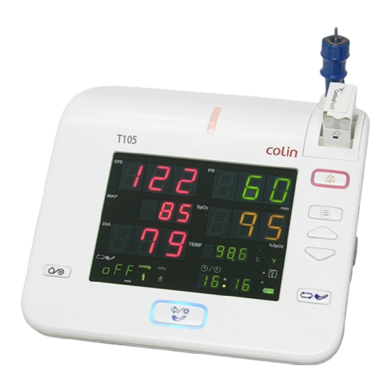
Page 23: Names And Functions Of Parts
NAMES AND FUNCTIONS OF PARTS Main Unit Power Switch Switches the power ON/OFF. To switch "OFF" the power, hold down this switch for 3 seconds. Cuff Start/Stop Starts and stops cuff measurement. Cuff Interval The interval for cuff measurement can be set. (HBP-T105 only) Clear Display Clear the measurement value display. - Page 24 Temperature The body temperature measurement probe is connected here. Measurement *1 Internal Remove this cover when mounting or replacing the internal battery. Battery Cover Roll Paper The roll paper is placed here. Holder *2 Non-Invasive The air hose for the cuff measurement is connected here. Blood Pressure Measurement (NIBP)
- Page 25 Explanation of Display SYS LED Displays the Systolic Pressure. MAP LED Displays the Mean Arterial Pressure. DIA LED Displays the Diastolic Pressure. INT LED Displays the Cuff Interval. (HBP-T105 Only) (For the setting method, see Page 25.) NIBP Unit Displays the Blood Pressure Unit. Icon NIBP Patient Displays the Blood Pressure Measurement mode.
- Page 26 This page is left intentionally blank.
-
Page 27: Preparation
2. Preparation... - Page 28 This page is left intentionally blank.
-
Page 29: Preparations Before Use
PREPARATIONS BEFORE USE Before connecting the power supply, use the following procedure to install the Installing the internal battery in the rear of the device. Internal Battery 1. Loosen the three screws and remove the battery cover. 2. Connect connector (A) of the internal battery to connector (B) of the device. - Page 30 Connect the power supply with the following procedure. Connecting the 1. Connect the power supply connector from the AC adapter to the device. Power Supply 2. Plug the AC adapter cable plug side into a medical three-prong socket with ground connector. When you connect the power supply, charging of the internal battery starts Charging the (Page 103).
- Page 31 Battery remaining Under about 5% (Flashing rapidly) In order to maintain the battery charge, Mediana recommends leaving the device plugged into AC power when it is not in use. If the device is not plugged in, the battery may lose its charge over time, even when powered off.
- Page 32 Checking and revising the Date and time About Utility The date and time can be checked in "Utility Mode". Mode For details on "Utility Mode", see "9. Setup" "Utility Mode" (Page 89). The time is checked in "Hour" set mode and the date is checked in "Year" set mode.
-
Page 33: Non-Invasive Blood
3. Non-Invasive Blood Pressure Measurement... - Page 34 This page is left intentionally blank.
-
Page 35: Measurement Preparation
MEASUREMENT PREPARATION Connect the air hose to the “Cuff Connection Port”. Connecting the Insert securely in the direction of the arrow until it clicks into place. Air Hose On the end of the air hose, install the cuff appropriate for the patient. The use of a patient-suitable cuff is an important factor for obtaining correct Cuff Selection measurement results. - Page 36 When you switch on the device power, check that the blood pressure Check before automatically stabilizes. Start of Blood After the check ends, the NIBP UNIT ICON and NIBP PATIENT ICON are lit Pressure Measurement Check that these icons are lit up before starting blood pressure measurement. Pressure stability check underway After completion of pressure stability check Example: When “Adult/Pediatric”...
- Page 37 Selecting the Measurement Mode About Utility The measurement mode can be selected in "Utility Mode". Mode For details on "Utility Mode", see "9. Setup" "Utility Mode" (Page 89). Measurement measurement mode selected "Measurement Mode mode selection (Adult/Neonate) Selection" screen. screen Press the [Menu/Enter] switch until the "Measurement Mode (Adult/Neonate) Selection"...
- Page 38 Connect the cuff hose to the air hose. Cuff Connection Adult/Pediatric Insert in the direction of the arrow. Cuffs Insert securely until it clicks into place. Neonatal/Infant Firmly insert the for-single-use cuff hose connector into the cuff hose For-Single-Use connector. Cuff Make sure that the connectors are tightly connected, as air leaks will prevent Note...
-
Page 39: How To Apply The Cuff
HOW TO APPLY THE CUFF 1. Place the hand of the patient with the palm of hand facing upward. Attaching the Cuff ф 2. Align the Artery Position Mark with the brachial artery. 3. Wrap the cuff snugly using both hands and securely fasten it with the hook and loop tape. - Page 40 4. Keep the level of the cuff at the same level as the heart during the measurement. 5. Maintain the height of the cuff-wrapped upper arm artery to that of the heart's right ventricle during measurements. Select a cuff to suitably fit the patient by wrapping the cuff edge around the Attaching arm and seeing that it fits well into the cuff size indicator as shown in the Neonatal Cuff...
-
Page 41: Manual Measurement
MANUAL MEASUREMENT Press the [Cuff Start/Stop] switch. The device will inflate to the initial inflation Commencing a pressure value, then measure. Measurement ■ Re-measure if the measurement cannot be performed. ■ If pressurization is insufficient, the pressure will automatically increase until the correct pressure is reached (this may occur even during a measurement). - Page 42 This page is left intentionally blank.
-
Page 43: Automatic Measurement (Hbp-T105 Only)
AUTOMATIC MEASUREMENT (HBP-T105 only) 1. When you press the [Cuff Interval] switch, the cuff measurement Monitoring Using interval setting value flashes. Cuff Intervals 2. Use the [Forward] or [Back] switch to change the measurement interval. Available intervals are: off, con, 1, 2, 2.5, 3, 5, 10, 15, 20, 30, 45, 60, 90, 120, and 180 minutes. - Page 44 This page is left intentionally blank.
-
Page 45: Continuous Measurement (Hbp-T105 Only)
CONTINUOUS MEASUREMENT (HBP-T105 only) 1. When you press the [Cuff Interval] switch, the cuff measurement interval Continuous setting value flashes. Measurements (CON) 2. Use the [Forward] or [Back] switch to set the setting to "CON". 3. If you do not press a switch for 10 seconds or press [Cuff Start/Stop], [Alarm Silence] or [Cuff Interval], "Setting Mode"... - Page 46 This device has a function for estimating the systolic pressure during the Quick SYS second and subsequent measurements in continuous measurement in adult mode. This function is called Quick SYS. There are some cases in which Quick SYS does not work (i.e., when the systolic pressure cannot be estimated).
-
Page 47: Other Functions
OTHER FUNCTIONS The "Initial Inflation Pressure" is the inflation value applied when the "Cuff Initial Inflation Interval" and "Smart Inflation" is set to "OFF" when the [Cuff Start/Stop] Value switch is pressed and the blood pressure is measured. (HBP-T105 only) For the HBP-T105S, this is the inflation value when "Smart Inflation"... - Page 48 Neonate Initial The neonate mode initial inflation pressure value setting is made on the inflation pressure "Neonate Initial Inflation Pressure Setting" screen. Press the [Menu/Enter] value setting screen switch until you reach the "Neonate Initial Inflation Pressure Setting" screen. When you reach the "Neonate Initial Inflation Pressure Setting" screen, the display becomes as follows: Changing the Use the [Forward] or [Back] switch to change the initial inflation pressure...
- Page 49 Smart Inflation™ means that the cuff pressure appropriate to the patient's Smart Inflation™ blood pressure value is automatically estimated and the cuff pressure raised to that pressure. Smart Inflation operates in the following cases: ■ When the measurement mode is set to "Adult/Pediatric". ■...
- Page 50 This is a high speed measurement function that can measure more quickly High Speed than conventional blood pressure measurement. The time the blood vessel is Measurement occluded is shorter, so the discomfort due to the measurement and any (Default setting is potential damage to subcutaneous tissue is reduced.
- Page 51 BP silent mode Use the [Forward] or [Back] switch to select "ON" or "OFF". selection Entering the BP When you have selected "ON" or "OFF", press the [Menu/Enter] switch to silent mode enter the selection. selection When you do, the selection screen display moves to the next setting item. Exiting the selection To end "Utility Mode"...
- Page 52 This page is left intentionally blank.
-
Page 53: After Measurement
AFTER MEASUREMENT When measurement ends, remove the cuff from the patient and use the procedure below to switch the “Cuff Measurement Interval” to “OFF”. For details about how to check the data, see “6.List screen” (Page 57) or “8.Recorder” (Page 69). The HBP-T105S has no interval setting. - Page 54 Clear Display (HBP-T105S only) Clear Each time you press the [Clear] switch, the measurement value display is cleared. measurement Press this when the patient is changed. value display Usage Press the [Clear] switch. method Display...
-
Page 55: Pulse Oximeter (Spo )
4. Pulse Oximeter (SpO (Only models with SpO... - Page 56 This page is left intentionally blank.
-
Page 57: Measurement Preparation
MEASUREMENT PREPARATION Connecting the Sensor Models with 1. Plug the extension cable into the SpO connector on the side of the ® Nellcor device. 2. Insert the SpO sensor onto the extension cable, lower the cover, and lock it. Models with 1. - Page 58 Sensor The use of a patient suitable sensor is an important factor for obtaining Selection correct measurement results. Carefully select a patient-suitable sensor from among those shown below. ® For Nellcor model ® The DURASENSOR DS-100A is a short-term usage sensor that ...
- Page 59 ® For Masimo The LNCS DC-I is a short-term reusable finger sensor. The other disposable sensors can be reused on the same patient only while the tape remains adhesive. Do not use any SpO sensor other than those specified. Note...
- Page 60 This page is left intentionally blank.
-
Page 61: Attaching Spo Sensor
ATTACHING SpO SENSOR For a reusable SpO sensor, carefully read the instruction manual that Reusable SpO comes with the sensor. Sensor ® The SpO sensor for the Nellcor model is shown below as an example. Open the SpO sensor and fit it securely on a fingertip. Have the cable on the fingernail side. - Page 62 For disposable SpO sensor, carefully read the instruction manual that Disposable SpO comes with the sensors. Sensor ® ® The example below uses a Nellcor OXISENSOR Peel off the protective film from the sticky surface. Attaching being aware that accurate measurement is made possible by the light emitting section and the light receiving section working together as a pair.
-
Page 63: Measurement
MEASUREMENT The measurement reading is displayed when this sensor is connected to Screen Display the device. Example If the SpO sensor has been dropped or subjected to strong physical shock, check for faults before use. Select the sensor appropriate for the patient. ... - Page 64 This page is left intentionally blank.
-
Page 65: Temperature Measurement
5. Temperature Measurement (Only models with body temperature measurement) - Page 66 This page is left intentionally blank.
-
Page 67: Measurement Preparation
MEASUREMENT PREPARATION Connect the body temperature probe connector to the body temperature Connecting the probe connection part on the rear of the device. Body Be careful to insert the connector in the correct direction. It can only be Temperature Probe inserted with the correct orientation. - Page 68 This page is left intentionally blank.
-
Page 69: Measurement
MEASUREMENT Always mount the probe cover before using the body temperature probe. Mounting the A probe cover is required to take a temperature measurement. Probe Cover Press the probe firmly into the probe cover, being careful not to press the probe cover release on the top of the probe. If the cover is not securely mounted, there is a danger of it coming loose or coming off in use. - Page 70 For axillary Use the probe with a blue cap. measurement Put the tip of the body temperature probe into the patient’s axillary and have the patient hold it in place by pressing with the arm. Hold the body temperature probe position constant and in such a way that its tip is touching the patient’s skin during body temperature measurement.
- Page 71 Screen Display Example After the end of measurement, hold the body temperature probe in the Existing same way as in the instructions for a syringe, press the probe cover Measurement removal button, and dispose of the used probe cover in a waste container. Return the body temperature probe to the probe holder on the top of the device.
- Page 72 This page is left intentionally blank.
-
Page 73: List Screen
6. List Screen... - Page 74 This page is left intentionally blank.
-
Page 75: List Screen
LIST SCREEN This can display past measurements (List Data) stored in memory. To list the display, press either the [Forward] or [Back] switch while the Explanation basic screen is displayed. List Screen [Forward] switch: Each time this switch is pressed, one old list data is displayed in reverse chronological order. - Page 76 List data can be deleted in “Setting Mode”, which is selected by pressing Deleting List Data the [Menu/Enter] switch. For additional information on “Setting Mode”, see “9. Setup” “Setting Mode” (Page 83) Delete list screen List data deletion is set on the “Delete List” screen. Press the [Menu/Enter] switch until the “Delete List”...
-
Page 77: Alarms
7. Alarms (The HBP-T105S only) - Page 78 This page is left intentionally blank.
-
Page 79: Alarm Settings (Hbp-T105 Only)
ALARM SETTINGS (HBP-T105 only) About Setting Mode An alarm can be set in “Setting Mode”, which is selected by pressing the [Menu/Enter] switch. For additional information on “Setting Mode”, see “9. Setup” “Setting Mode” (Page 83). Alarm Setting Press the [Menu/Enter] switch until the “Alarm Setting” screen you want to Screens change appears. - Page 80 This page is left intentionally blank.
-
Page 81: Alarm Operations (Hbp-T105 Only)
ALARM OPERATIONS (HBP-T105 only) If the patient’s measurement exceeds the value set for an alarm, Alarm Triggering an alarm is triggered. When an alarm is triggered, The alarm sounds. The alarm lamp flashes. The edge of the [Alarm Silence] switch flashes. The corresponding measurement value is displayed flashing. - Page 82 Silencing an Alarm Press the [Alarm Silence] switch. The alarm sound stops. The alarm lamp lights up. The edge of the [Alarm Silence] switch lights up. The corresponding measurement value continues to flash. If an alarm (other than for a cuff measurement value) set with the ...
- Page 83 Alarm Setting Range The following shows the alarm setting ranges. No alarm is issued until the measured value exceeds the upper alarm setting or falls below the lower alarm setting. Note For details on the alarm sound see “Other Labels”→(Page 4).
- Page 84 This page is intentionally left blank.
-
Page 85: Recorder
8. Recorder (Only models with recorder) - Page 86 This page is left intentionally blank.
-
Page 87: Preparations Before Use
For the above reasons, make a copy when storing as a document of permanent record. Please use only roll paper from Mediana. If you use other paper, the recording may be thin or it may cause a paper jam or other breakdown. - Page 88 This page is left intentionally blank.
-
Page 89: Manual Recording
MANUAL RECORDING Press the [Record] switch. The measurement data is recorded. Record Pattern The record pattern will be one of the types below. You can select the desired type with a setting. (For details on how to make this setting, please see Page 74.) ... - Page 90 Detailed list recording (LST 2) Patient IDs are recorded only if there are IDs in the list data. If an ID is not entered or the patient changes, then the ID section is left blank or recorded as “Unknown”. The ID section is not recorded unless the user enters an ID at least once after powering on.
- Page 91 Measurement value recording (OSCL) If there is no NIBP measurement value, this recording is not executed. Records the measurement value data being displayed at the moment. An ID is recorded only if there is an ID when recording starts. If an ID is not entered or the patient changes, then the ID section is ...
- Page 92 List Record Pattern Selection About Utility Mode The list record pattern can be selected in “Utility Mode”. For details on “Utility Mode”, see “9. Setup” “Utility Mode” (Page 89). List record pattern The list record pattern is selected on the “List Record Pattern Selection” selection screen screen.
-
Page 93: Automatic Recording
AUTOMATIC RECORDING When the measurement record selection becomes anything other than “OFF” in “Utility Mode”, the measurement value at the moment measurement ends is recorded. Record Pattern The record pattern will be one of the types below. You can select the desired type with a setting. - Page 94 Measurement value recording (OSCL) If there is no NIBP measurement value, this recording is not executed. Records the measurement value data being displayed at the moment recording starts. An ID is recorded only if there is an ID when recording starts. If an ID is not entered or the patient changes, then the ID section is ...
- Page 95 Measurement Record Selection About Utility Mode Recording for measurement can be selected in “Utility Mode”. For details on “Utility Mode”, see “9. Setup” “Utility Mode” (Page 89). Measurement record This function will record measurement data automatically at the end of selection screen the measurement.
- Page 96 Deleting List Data Refer to Chapter 6 “List Screen” (Page 57). Recorder Error Recorder errors are detected and announced with the RECORDER INDICATOR. If the paper runs out during recording, reload paper. The recording does not resume automatically. Press the [Record] switch. Note that the recording starts over from the beginning.
-
Page 97: Setup
9. Setup... - Page 98 This page is left intentionally blank.
-
Page 99: How To Setup
HOW TO SETUP For adjusting settings, there are two modes: “Setting Mode” and “Utility Mode”. The following settings are made in “Setting Mode”: Settings in 1. SYS upper limit alarm setting* Setting Mode 2. SYS lower limit alarm setting* 3. DIA upper limit alarm setting* 4. - Page 100 This page is left intentionally blank.
-
Page 101: Setting Mode
SETTING MODE Setting Procedure 1. How to enter Press the [Menu/Enter] switch. setting mode The system goes into “Setting Mode”. 2. Setting screen Press the [Menu/Enter] switch until the desired setting screen appears. selection Each time you press the [Menu/Enter] switch, the setting screen changes in the following order. - Page 102 Setting Method for Each Item 1. SYS upper limit This sets the SYS upper limit alarm value. alarm setting For details, see “7. Alarms” “Alarm Setting” (Page 61). (HBP-T105 only) 2. SYS lower limit This sets the SYS lower limit alarm value. alarm setting For details, see “7.Alarm”...
- Page 103 5. PR upper limit This sets the PR upper limit alarm value. alarm setting For details, see “7.Alarms” “Alarm Setting” (Page 61). (HBP-T105 only) 6. PR lower limit This sets the PR lower limit alarm value. alarm setting For details, see “7.Alarms” “Alarm Setting” (Page 61). (HBP-T105 only) 7.
- Page 104 9. Alarm volume This sets the alarm volume. setting Clear measurement Press the [Menu/Enter] switch until the “Alarm Volume Setting” screen value display appears. When the “Alarm Volume Setting” screen appears, the display becomes as follows: Changing the setting Use the [Forward] or [Back] switch to change the setting value. value Clear measurement When you have selected the setting value, press the [Menu/Enter] switch...
- Page 105 11. Cuff This sets the cuff measurement interval. measurement interval selection (HBP-T105 only) Cuff measurement Press the [Menu/Enter] switch until the “Cuff Measurement Interval interval selection Selection” screen appears, or press the [Cuff Interval] switch. screen When the “Cuff Measurement Interval Selection” screen appears, the display becomes as follows: Selecting the value Use the [Forward] or [Back] switch to change the value.
- Page 106 12. Delete list The list data is erased. For details, see “6. List Screen” “Deleting List Data” (Page 57). Hold down the [Alarm Silence] switch for at least 3 seconds.
-
Page 107: Utility Mode
UTILITY MODE Setting Procedure 1. How to enter Switch the power “OFF”. Utility Mode While holding down the [Cuff Start/Stop] switch, press the [Power] switch. The device goes into “Utility Mode”. 2. Setting screen Each time the [Menu/Enter] switch is pressed, the setting screen switches in selection order to as follows: (Some screens are only displayed if the corresponding option is installed.) - Page 108 3. Charging the Change the setting contents with the [Forward] switch or the [Back] setting contents switch. 4. Entering the Press the [Menu/Enter] switch. setting contents The setting content is entered and the display moves to the next setting item. 5.
- Page 109 Setting Method for Each Item 1. Measurement Adult: Set to this value when using reusable or disposable cuffs for adult mode and pediatric patients. (Adult.Neonate) Neonate: Set to this value when using the disposable cuffs for neonates. selection For details, see “3. Non-Invasive Blood Pressure Measurement (NIBP)” “Selecting the Measurement Mode”...
- Page 110 5. High Speed When this function is switched “ON”, blood pressure is measured in a measurement shortened time. ON/OFF When this function is used, the time the blood vessel is occluded is selection shorter, so potential discomfort due to the measurement and possible (Default is OFF) damage to subcutaneous tissue is reduced.
- Page 111 6. BP silent mode When this function is switched “ON”, the pump sound is suppressed. selection For details, see “3. Non-Invasive Blood Pressure Measurement (NIBP)” “BP Silent Mode” (Page 33). 7. Blood pressure When this function is switched “ON”, a sound is played when blood measurement pressure measurement ends.
- Page 112 8. measurement This selects the list record pattern for measurement. record selection OFF: Do not record. (Automatic LST: Simple list recording Recording) OSCL: Measurement value recording Select any one of the above. For details, see “8. Recorder” “Automatic Recording” (Page 75). 9.
- Page 113 10. External output This screen makes settings related to external output selection. selection 11. List record When the “SAVE” option is selected, the device enters a save mode pattern selection after three minutes of no activity. If any operation is carried out (for (Manual example a measurement update or nay operator action) or an alarm is Recording)
- Page 114 13. External output This sets the minute for the clock. selection For details, see “2.Preparations Before Use” “Checking and Revising the Date and Time” (Page 14). 14. External output This sets the year for the clock. selection For details, see “2.Preparations Before Use” “Checking and Revising the Date and Time”...
- Page 115 17. Date format The date format for recording can be selected from the following. selection YMD/:YYYY/MM/DD DMY/:DD/MM/YYYY YMD-:YYYY-MM-DD DMY-:DD-MM-YYYY The setting procedure is as follows: Date format Press the [Menu/Enter] switch until the “Date Format Selection” screen selection screen appears. When the “Date Format Selection”...
- Page 116 19. LAN group This screen makes settings related to LAN group numbers. number setting Contact Mediana Technical Service when making these settings. (May not display depending on the External output selection.) 20. MAP display This screen makes settings related to LAN bed numbers.
- Page 117 21. Default setting All the setting values are set to their factory-set values. For details on the factory settings, see "Default Setting" (Page 127). Default setting Press the [Menu/Enter] switch until the "Default Setting" screen appears. screen When the "Default Setting" screen appears, the display becomes as follows: Hold down the [Alarm Silence] switch for at least 3 seconds.
- Page 118 This page is left intentionally blank.
-
Page 119: Internal Battery
10. Internal Battery... - Page 120 This page is left intentionally blank.
-
Page 121: Internal Battery
INTERNAL BATTERY When the battery is installed in the device, the device can be run by About the battery. Also, even when using the AC power supply, if the AC power Internal Battery supply should be disconnected for any reason, the device switches automatically to battery operation. - Page 122 The battery icon display shows the usage state. Battery Icon Display Battery Icon Power Supply Battery state display Charging (Battery indicator: Orange) Running on Fully charged state AC power (Battery indicator: Green) supply Battery not connected/battery abnormality (Battery indicator: Off) Adequate charge Green (Battery remaining over about...
- Page 123 When the battery is running low and it becomes impossible to run the Battery Low device on the battery, the battery indicator flashes red and the alarm sounds. Connect the AC adapter to the device and the AC adapter cable to ...
- Page 124 This page is intentionally left blank.
-
Page 125: Appendix
11. Appendix... - Page 126 This page is intentionally left blank.
-
Page 127: Error Code Table
RAM. Switch the power for the device "OFF", then "ON" again. If this does not solve the problem, immediately stop using device and contact Mediana Technical Service. Battery is discharged An error was detected. Charge the battery. If this does not... - Page 128 "OFF", then "ON" High Possible again. If this does not solve the problem, immediately stop using it and contact Mediana Technical Service. Sound IC error A sound function error was detected. Switch the power "OFF", then "ON" again. If the...
- Page 129 Check the patient and conditions of measurement, and measure again with the cuff. Cease use immediately if the E09 error recurs and contact Mediana Technical Service. Readings outside Check the condition of the NIBP range patient.
- Page 130 In case of E10, NIBP measurement value and the error code are displayed alternately. Error Sound Priority Possible Causes Check items code Type Silence E11* Pressure rise not The cuff pressure rise was not completed within completed even though the required time.
- Page 131 Error Sound Priority Possible Causes Check items code Type Silence E14* Insufficient Measurement failed because of pressurizing value to insufficient pressurizing. There is through None compute patient a possibility that standard cuff 3rd time (Re- blood pressure. pressure might be detected Low (Re- measure) incorrectly due to noises, motion...
- Page 132 Error Sound Priority Possible Causes Check items code Type Silence E17* Measurement time The measurement time exceeds has exceeded the expected time, so the specified time. measurement was ended in Specified time: 160 order to avoid patient seconds (adult), 80 discomfort.
- Page 133 If switching power High Possible OFF/ON has no effect it is possible that a fault has occurred. Contact Mediana Technical Service. * For HBP-T105S, the alarm does not sound. For remeasurement, a period is displayed at the error code.
- Page 134 Medium Possible effect the problem may be within the device. In this case, cease use immediately and contact Mediana Technical Service. E31* Low signal level. Pulse Signal obtained from sensor wave cannot be is weak. SpO could not be recognized properly.
- Page 135 Sensor breakdown Replace the sensor. If replacing the sensor does not solve the problem, stop using Medium Possible measurement and contact Mediana Technical Service. Internal module initializing Do not move the sensor mounting location. If this state continues for longer None...
- Page 136 "OFF", then "ON" again. If this does not solve the problem, there is a possibility that the device has broken down, so immediately stop using it and contact Mediana High Possible Technical Service. Internal module...
-
Page 137: Principles
PRINCIPLES Non-Invasive Pressure Measurement Principles Oscillometric The beat in the pulsation generated by the contraction of the heart is captured as method the pressure inside the cuff to measure the blood pressure. If the cuff wrapped around the upper arm is pressurized sufficiently, the blood flow stops, but the beat of the pulsation is present and the pressure inside the cuff receives this and oscillates. - Page 138 Basic Principles of SpO Measurement Pulse oximetry The ratio of oxidized hemoglobin linked to oxygen in arterial blood and method reduced hemoglobin that is not linked is known as the SpO ratio and the pulse oximeter method is used to measure that ratio. Functional saturation (%) = 100 ×...
- Page 139 However, the lights transmitted through the measurement site also contain data other than the arterial blood targeted for measurement. At this time, the data for diastole of the heart chamber includes data other than arterial blood data, so this reading is used as the standard reading for measurements.
- Page 140 ® Principle of Operation (For Masimo model) Principle of The Masimo® SET MS board pulse oximeter is based on three operation principles: 1. Oxyhemoglobin and deoxyhemoglobin differ in their absorption of red and in infrared light (spectrophotometry). 2. The volume of arterial blood in tissue and the light absorbed by the blood changes during the pulse (plethysmograpby).
- Page 141 Again, R is the ratio of two arterial pulse-added absorbance signals and its value is used to find the saturation SpO in an empirically derived equation into the oximeter's software. The values in the empirically derived equation are based upon human blood studies against a laboratory co-oximeter on healthy adult volunteers in induced hypoxia studies.
- Page 142 This page is intentionally left blank.
-
Page 143: Default Setting
DEFAULT SETTING The setting items, factory settings, and backup information for this device are listed in the table below. All settings can be returned to their factory-set values with "Utility Mode" "Default setting". For details, see Page 101. The backups are as follows. Items with "O": Settings are retained even if the power is switched off. - Page 144 Factory Setting item Back up settings Measurement Mode Adult Blood pressure unit mmHg Adult 180 mmHg 120 mmHg Init. Pres. NIBP* High speed Measurement Smart Inflation NIBP Interval* BP silent mode Temperature Display unit ˚F Sound Alarm volume* Pulse rate volume Sound when blood pressure measurement ends Recorder...
-
Page 145: Maintenance
MAINTENANCE Medical equipment including the HBP-T105/S series must be maintained Maintenance to ensure functionality and to secure the safety of patients and operators. Inspection and Daily checks and maintenance should be performed by the operator. Safety In addition, qualified personnel are necessary to maintain the performance Management and the safety, and to conduct periodic inspections. - Page 146 For more information, refer to the service manual. Qualified service personnel in the user's institution should perform periodic inspections of the device. If service is necessary, contact qualified service personnel or Mediana Technical Service...
- Page 147 Accessory Care Do not put solutions on the accessories or wet the connectors. When using disinfecting solutions, be sure to follow manufacturer instructions. Do not use solvents (such as thinner and benzene) or abrasive Note cleaning powders for cleaning, as these may damage the surface of accessories.
- Page 148 This page is intentionally left blank.
-
Page 149: Checking Before Use
CHECKING BEFORE USE Prior to daily use, the following points should be checked: Each Day Is there any deformation or damage due to the device or accessories Before Turning being dropped? ON the Power, Check for the Following External The device is not dirty. - Page 150 Recorder* Press the [Record] switch and check that the instrument is recording. Non-Invasive blood The person checking the cuff should wrap the cuff around arm, pressure perform cuff measurement and check to see that blood pressure is measurement in the vicinity of normal measurements. (NIBP) While measurement is in progress, bend the relevant arm and move body to halt discharge and during this halt check that cuff pressure...
-
Page 151: Power On Display
POWER ON DISPLAY Once the power is turned “ON”, the following display will appear in order in roughly 2 second intervals. - Page 152 This page is intentionally left blank.
-
Page 153: Maintenance Checks
Cords are not damaged and connections are not loose. The sensors attached to the patient are only those supplied or specified by Mediana. The roll paper is the specified type and enough stock is maintained. AC ADAPTER ... - Page 154 This page is intentionally left blank.
-
Page 155: Troubleshooting
TROUBLESHOOTING If the device is not functioning properly, check the following before contacting Mediana Technical Service. Main Unit Power cannot be turned ON Cause Action adapter cable Check the AC adapter cable disconnected or loose. connections. The device heats up... - Page 156 Non-Invasive Blood Pressure Measurement (NIBP) Pressure does not rise after [Cuff Start/Stop] switch is pressed. Cause Action Cuff hose connection is loose. Check air hose connection Cuff air is leaking. Hose is Replace cuff. Check for kinked kinked if pressure is displayed. and remove them.
- Page 157 Measurement readings unreliable Cause Action Air discharge is fast. Check loss cuff hose connection. Perform measurement in tandem with stethoscope examination of pulse. Stethoscope Place stethoscope on artery and listen while watching Blood Pressure Monitor pressure display. Blood pressure fluctuates greatly due to physiological reactions. Check the following items, as one of them may be the cause.
- Page 158 Arterial Oxygen Saturation by Pulse Oximeter Measurement (SpO Measurement not possible Check the patient, as shock, poor peripheral circulation due to low blood pressure or constriction of arteries at sensor attachment point may be possible causes. Check to see if sensor has become detached. ...
- Page 159 Problems with E-Temp (Verify against Error Messages for further information) No temperature measurement Cause Action Disconnected probe or cable Connect probe or change, if defective. Probe out of well on power-up Insert probe into probe well, then try measurement again. Defective Probe If “E40”...
- Page 160 Temperature reading unreasonable Cause Action Patient’s mouth was open. Ask patient to keep mouth closed during measurement. Improper probe placement Verify placement of probe as shown on page 51. Unlike slower temperature measurement techniques, this fast measurement requires the user to make sure the probe is placed directly against the sublingual artery in the back, center of the tongue.
-
Page 161: Disposal
DISPOSAL As there is a risk of environmental pollution, follow your applicable Description Federal, state and local legal regulations regarding disposal or recycling of this equipment and batteries. The main constituents of each part are listed in the table below. As there is a risk of infection, do not recycle patient attachments such as cuffs and sensors, but dispose of them as instructed by your facility's procedures and applicable regulations. - Page 162 This page is intentionally left blank.
-
Page 163: Specification
SPECIFICATION General Measurement Parameter NIBP Temperature *2 *1: Only models with SpO *2: Only models with body temperature measurement Dimension Main unit:239(W)x150(H)x239(D)mm (9.41x5.90x9.41in) AC ADAPTER:150(W)x47(H)x75(D)mm (5.90x1.85x2.95in) Weight Main Unit with Recorder: 2.1kg (4.63lbs) No recorder: 1.9kg (4.19lbs) AC ADAPTER: 0.5kg (1.11lbs) Internal Battery: 1.5kg (3.31lbs) Display NIBP(SYS) - Page 164 General standard 93/42/EEC as amended by 2007/47/EC Medical Device Directive EN ISO13485:2003 Quality System - Medical Devices – Requirements for regulating purposes EN ISO14971:2009 Application of risk management to Medical devices IEC 60601-1:1988+A1:1991+A2:1995, EN 60601-1-:1996 Medical electrical equipment-Part1:General requirements for safety IEC60601-1-4:2000, EN60601-1-4:1996+A1:1999 Collateral standard for Programmable medical systems...
- Page 165 IEC 60601-1-1. If in doubt, consult your technical services department or Mediana Technical Service.
- Page 166 Environmental Conditions Power supply AC ADAPTER Input voltage range AC 100V to 240V Rated Current 4.28A Frequency 50 / 60 Hz Output voltage range DC 14V±5% AC plug NEMA5-15P Battery Type 12V, 3.2Ah Measurement Time 6 hours maximum ■ When operating under the following conditions: ...
- Page 167 Non-Invasive Blood Pressure (NIBP) Measurement technology Oscillometric Measurement Method Dynamic Linear Deflation method Pressure display range Adult/pediatric mode 0 to 299 mmHg Neonatal mode 0 to 149 mmHg Pressure display accuracy Less than ±3mmHg NIBP measurement range Adult/pediatric mode 60 to 250 mmHg 45 to 235 mmHg 40 to 200 mmHg Pulse rate...
- Page 168 Alarm range Adult/pediatric mode SYS upper limit 60 to 260 mmHg Default 200 mmHg SYS lower limit 50 to 250 mmHg Default 70 mmHg DIA upper limit 40 to 240 mmHg Default 160 mmHg DIA lower limit 30 to 230 mmHg Default 30 mmHg Pulse rate upper...
- Page 169 ® Pulse Oximeter (Models with Nellcor Measurement method 2 wave length pulse wave type Measurement range 70 to 100% SpO Pulse rate 20 to 250/min Accuracy Specifications Accuracy specifications are based on controlled hypoxia studies with healthy non-smoking adult volunteers over the specified saturation SpO range(s).
- Page 170 Population Healthy and recruited from local population. Comprised of both men and women, subjects spanned a range of skin pigmentations and ranged in age from 18-50 years old. MAX-N Clinical functionality has been demonstrated on a population of hospitalized neonate patients. The observed SpO accuracy was 2.5% in a study of 42 patients with ages of 1 to 23 days, weight from 750...
- Page 171 ® Pulse Oximeter (Models with Nellcor Measurement method 2 wave length pulse wave type Measurement range 1 to 100% SpO Pulse rate 25 to 240/min Accuracy Specifications Accuracy specifications are based on controlled hypoxia studies with healthy non-smoking adult volunteers over the specified saturation SpO range(s).
- Page 172 For more information visit: http://www.masimo.com/cpub/clinpubs.htm Pulse rate accuracy ±3/min Display update Less than 30 sec Defibrillator protection Protected Alarm range upper limit 71 to 100% SpO Default 100% SpO lower limit 70 to 99% SpO Default 90% SpO Pulse rate upper limit 30 to 260/min Default...
- Page 173 E-Temp (Models with Body Temperature Measurement) ® Method: TurboTemp Electronic Predictive Thermometer Probe types: Oral/Axillary - # 2887A Rectal- # 2888A Modes: Predictive- Measurement complete within 10 seconds of tissue contact Monitoring- Continuous temperature measurement Display resol: ±0.1°C (±0.2°F) Display range: Predictive Mode 35.6 ~ 41.1°C (96.1~105.9°F) Monitoring Mode 26.7 ~ 42.2°C (80.1~107.9°F) Accuracy:...
- Page 174 FCC STATEMENT POTENTIAL FOR RADIO/TELEVISION INTERFERENCE (for U.S.A. only) This product has been tested and found to comply with the limits for a Class B digital device, pursuant to part 15 of the FCC rules. These limits are designed to provide reasonable protection against harmful interference in a residential installation.
- Page 175 Electromagnetic Immunity (IEC60601-1-2) Immunity test IEC60601-1-2 Compliance level Electromagnetic test level environment - guidance Electrostatic ±6 kV contact ±6 kV contact Floors should be wood, concrete or discharge (ESD) ±8 kV air ±8 kV air ceramic tile. If floors are covered IEC 61000-4-2 with synthetic material, the relative humidity should be at least 30 %.
- Page 176 Immunity test IEC60601-1-2 Compliance Electromagnetic test level level environment - guidance Portable mobile communications equipment should be used no closer to any part of the HBP-T105/S, including cables, than recommended separation distance calculated from the equation applicable to the frequency of the transmitter.
- Page 177 Recommended Separation Distances: Recommended separation distance between portable and mobile RF communications equipment and the HBP-T105/S The HBP-T105/S is intended for use in an electromagnetic environment in which radiated RF disturbances are controlled. The customer or the user of the HBP-T105/S can help prevent electromagnetic interference by maintaining a minimum distance between portable and mobile RF communications equipment (transmitters) and the HBP-T105/S as recommended below, according to the maximum output power of the communications equipment.
- Page 178 This page is intentionally left blank.
-
Page 179: Optional Accessories
OPTIONAL ACCESSORIES Optional Accessories for consumption and options may be required from the start, Accessories depending on conditions of use. In view of this, please order the necessary accessories. - Page 180 NIBP optional Accessory Name Parts Name Parts Code Infant C030101A-NLR Child/Small Adult C030103A-NLR Adult C030107A-NLR Reusable Cuffs (With Rectus Fitting) Large Adult C030109A-NLR Long Adult XC030115A-NLR Thigh C030111A-NLR Infant C0400011B Child/Small Adult C0400013B Disposable Cuff for Adult Adult C0400015B or Child Large Adult C0400019B (With Luer Fitting) *1...
- Page 181 ® ® For Nellcor Except for DURASENSOR , products below are for single-patient use only. When in use, they are connected to the standard accessory extension cable (DOC-10). Pulse oximeter optional accessory ® Nellcor is a registered trademark of Nellcor Puritan Bennett Incorporated. ®...
- Page 182 ® For Masimo Except for LNCS DC-I, products below are for single-patient use only. When in use, they are connected to the extension cable (LNC-10). Pulse oximeter optional accessory ® Masimo is a registered trademark of Masimo Corporation.
- Page 183 Temperature optional accessory (Only models with body temperature measurement) Optional accessory (Only models with recorder)
Need help?
Do you have a question about the HBP-T105 Series and is the answer not in the manual?
Questions and answers