Sign In
Upload
Manuals
Brands
Mediana Manuals
Medical Equipment
D500
Mediana D500 Manuals
Manuals and User Guides for Mediana D500. We have
2
Mediana D500 manuals available for free PDF download: Operator's Manual, Service Manual
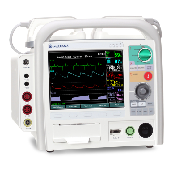
Mediana D500 Operator's Manual (222 pages)
Defibrillator/Monitor
Brand:
Mediana
| Category:
Medical Equipment
| Size: 5 MB
Table of Contents
Table of Contents
3
Contents
9
Safety Information
9
General Safety Information
9
Warning
9
Cautions
14
Introduction
15
Intended Use for the D500
15
Indications for Use
15
About this Manual
17
Identifying the D500 Configurations
17
Figures
19
Description of the Defibrillator/Monitor
19
Front Panel Components
19
Figure 1. Front Panel Components
19
Tables
20
Table 1. the Defibrillator/Monitor Controls
20
Top Panel Components
21
Figure 2. Top Panel Components
21
Table 2. the Defibrillator/Monitor Controls on Paddle
21
Rear Panel Components
22
Figure 3. Rear Panel Components
22
Left Panel Components
23
Right Panel Components
23
Figure 4. Left Panel Components
23
Figure 5. Right Panel Components
23
Table 3. Panel and Label Symbols
24
Displays
25
Figure 6. Displays
25
Figure 59. Etco
26
Figure 60. Etco
26
Table 4. Display Symbols
26
Table 5. Display Colors Factory Defaults
27
Setting up the Defibrillator/Monitor
29
Unpacking and Inspection
29
List of Components
30
Table 6. Standard Accessories
30
Table 7. Optional Accessories
31
Power Cable Connections
32
Figure 7. AC Power Connection
32
Measurement Cable Connections
33
Figure 8. DC Power Connection
33
Battery Operation
35
Operating the Defibrillator/Monitor on Battery Power
36
Figure 9. Battery Placement
36
Table 8. Front Panel Indications for Power Source
36
Battery Status Indication
37
Table 9. the Defibrillator/Monitor Battery Status Icon
37
Using the Defibrillator/Monitor
39
Turning on and off the Defibrillator/Monitor
40
Figure 10. Mode Select Knob
40
Setting Date and Time
41
Figure 11. Select Date/Time Menu
41
Table 10. Date/Time Menu
41
Continued Use
42
Setting the Main Screen
42
Figure 12. Setup: Display Mode Menu
42
Figure 13. Normal Screen (4 Waveform, Defibrillation Mode, Full Option)
43
Figure 14. Large Numeric Screen (2 Waveform, Monitor Mode, Full Option)
43
Figure 15. Black-White Screen (4 Waveform, Defibrillation Mode, Full Option)
44
Alarms and Limits
45
General
45
Alarm Priority and Messages
46
Figure 16. Volume Menu Display
46
Table 11. High Priority Alarm
46
Table 12. Medium Priority Alarm
47
Figure 51. Spo
48
Table 13. Low Priority Alarm
48
Table 14. Informative Messages
49
Table 15. Defibrillator Messages
49
Visual Alarm Indication
51
Audible Alarm Indication
51
Verifying Audible Alarm Indication
51
Table 16. Visual Alarm Characteristics
51
Table 17. Audible Alarm Characteristics
51
Changing Alarm Limits
52
Figure 17. Alarm Limit Menu
52
Table 18. Alarm Limits Ranges
53
Audio Paused and off
54
Table 19. Bell Icon
54
Ecg Monitoring
57
General
58
Setup Connections
58
Figure 18. Standard 3 Electrode Placement
58
Figure 19. 5 Electrode Placement
59
Table 20. ECG Lead Colors
59
Table 21. ECG Lead Pairs
59
12-Lead ECG
60
Figure 20. Varying Choice of Baselines
62
Figure 21. Baseline at the Level of QRS Onset as Used by the Glasgow Program
62
Figure 22. Illustration of Isoelectric Segments I and K
62
Figure 23. Definitions for QRS End / ST Junction
63
Preparing the 12 Lead
64
Figure 24. 12 Lead Placement
64
Calculation Feature
65
Figure 25. Measurement Reference
65
Table 22. Measurement Matrix
66
Figure 26. 12-Lead ECG Preview Screen
67
Description of HR/PR Menu Functions
68
Figure 27. HR/PR Display
68
Figure 28. ECG Waveform Display
68
Figure 29. HR/PR Menu
68
Table 23. HR/PR Menu
68
HR/PR Source
69
Aed(Automated External Defibrillator) MODE
71
2010 AHA Guidelines for CPR and ECC
74
Major Changes in the 2010 AHA Guidelines for CPR and ECC
74
CPR Guidelines 2010
75
AHA 2010 Configuration
78
Note Performing CPR
78
Description of AED Mode Menu Functions
78
Figure 31. Patient Info: ID Menu
79
Table 24. AED Mode Menu
79
Manual Mode
81
General
81
Preparing for Defibrillation
82
Operating the Manual Mode of Defibrillator/Monitor
82
Figure 32. Manual Mode Screen
82
Defibrillating (Async Mode)
83
Synchronized Cardioversion (Sync Mode)
83
Description of Manual Mode Menu Functions
85
Figure 33. Manual Mode Menu
85
Table 25. Manual Mode Menu
85
Figure 34. Setup Menu
87
Figure 35. Alarm Limit Menu
89
Figure 36. Patient Info: ID Menu
89
Monitor Mode
91
General
91
Description of Pacing Mode Menu Functions
91
Figure 37. Monitor Mode Menu
91
Table 26. Monitor Mode Menu
91
Figure 38. Setup Menu
94
Figure 40. Patient Info: ID Menu
95
Pacing Mode
97
General
97
Demand Mode and Fixed Mode
98
Operating the Pacing Mode of Defibrillator/Monitor
98
Demand Mode Pacing
98
Figure 41. Pacing Mode Screen
98
Fixed Mode Pacing
99
Description of Pacing Mode Menu Functions
100
Table 27. Pacing Mode Menu
100
Figure 43. Setup Menu
102
Figure 44. Alarm Limit Menu
103
Figure 45. Patient Info: ID Menu
103
Nibp Monitoring
105
General
106
Theory of Operation
106
Setup Connections
109
Description of NIBP Menu Functions
110
Figure 46. NIBP Display
110
Figure 47. NIBP Menu Display
110
Table 28. Cuff Size
110
Table 29. NIBP Menu
110
Spo MONITORING
113
General
114
Theory of Operation
115
Figure 48. Oxyhemoglobin Dissociation Curve
116
Clinical Studies
117
Table 30. Demographic Data
117
Table 31. Spo2 Accuracy for Nellcor™ Sensors
117
Figure 49. Modified Bland-Altman Plot
118
Setup Connections
119
Table 32. Spo2 Sensors
119
Figure 50. Spo2 Display
120
Figure 52. Spo 2 Waveform Display
120
Menu Display
120
Table 33. Spo2 Menu
120
Respiration Monitoring
121
General
121
Theory of Operation
122
Setup Connections
122
Description of Respiration Menu Functions
123
Figure 53. Respiration Display
123
Figure 54. Respiration Waveform Display
123
Figure 55. Respiration Menu Display
123
Capnography Monitoring
125
General
126
Theory of Operation
126
Setup Connections
127
Calibrating the CO Sensor
127
Figure 56. Connection for Mainstream
127
Figure 57. Connection for Sidestream
128
Description of Etco Menu Functions
129
Figure 58. Etco 2 Display
129
Table 35. Etco2 Menu
129
Temperature Monitoring
131
General
131
Theory of Operation
131
Setup Connections
131
Table 36. Temperature Sensors
131
Description of Temperature Menu Functions
132
Figure 61. Temperature Display
132
Figure 62. Temperature Menu Display
132
Table 37. Temperature Menu
132
Ibp Monitoring
133
General
134
Theory of Operation
134
Setup Connections
134
Figure 63. IBP Connections
134
Description of IBP 1 Menu Functions
135
Figure 64. IBP 1 Display
135
Figure 65. IBP 1 Waveform Display
135
Figure 66. IBP 1 Menu Display
135
Table 38. IBP 1 Menu
135
Description of IBP 2 Menu Functions
136
Figure 67. IBP 2 Display
136
Figure 68. IBP 2 Waveform Display
136
Figure 69. IBP 2 Menu Display
136
Table 39. IBP 2 Menu
137
Self-Test Function
139
General
139
Functions to be Tested in Self-Test
140
Self-Test Result Transmission (if Configured with Wireless Module Option)
140
Self-Test Result Printing
140
Figure 70. Auto Self-Test Display
140
Table 40. Self-Test Functions
140
External Shock Test
141
Trouble Shooting
141
Figure 71. External Shock Test
141
Table 41. Trouble Shooting of Self-Test
141
Event
143
General
143
Event Data List Display
143
Figure 72. Event Data List Display
143
Event Review Display
144
Figure 73. Event Review Display
144
12 Lead Record Display
145
Figure 74. 12 Lead Record Display
145
Figure 75. Patient Info Menu
145
Real-Time Data
147
General
147
Real-Time Data Menu
147
Figure 76. Real-Time Data Menu
147
Real-Time Data Recording
148
Header Recording
148
Event Messages Recording
148
Figure 77. Real-Time Print (Header and Event Messages)
148
Waveform Recording
149
Shock Information Recording
149
Trend Recording Auto Print
149
Download
149
Print Setting
149
Figure 78. Real-Time Print (Waveform, Shock Info and Trend)
149
Menu Structure
151
Figure 30. AED Mode Menu
154
Figure 42. Pacing Mode Menu
155
Table 34. Respiration Menu
165
Printing
167
General
167
Printer Settings
167
Figure 79. Printer Setting Menu
167
Print-Out
168
Figure 80. Print-Out
168
Figure 81. Print-Out on Shock
168
Figure 82. Print-Out on 12 Lead ECG Data
169
Figure 83. Print-Out on Self-Test Result
169
Figure 84. Print-Out on Setting Information
170
External Interface
171
General
171
SD Memory Card
171
Table 42. Wireless Status Icon and Bed Number Icon
171
Central System Communication
172
Maintenance
173
Recycling and Disposal
173
Returning the Defibrillator/Monitor and System Components
174
Service
174
Periodic Safety Checks
174
Cleaning
174
Battery Maintenance
175
Loading Printer Paper
176
Figure 85. Printer Paper Replacement
176
Troubleshooting
177
General
177
Obtaining Technical Assistance
177
EMI (Electromagnetic Interference)
178
Factory Defaults
181
General
181
Parameter Ranges and Default Settings
181
Table 43. Parameter Ranges and Factory Defaults
181
Specification
189
Display
189
Controls
189
Alarms
189
Physical Characteristics and Printer
189
Electrical
190
Environmental Conditions
191
Tone Definition
192
Measurement Parameters
193
Event
199
Defibrillator (Technical Specification)
200
Table 44. Delivered Energy at Every Defibrillator Settings into a Range of Loads
203
Figure 86. Biphasic Waveforms at 300 Joules and 360 Joules
204
Figure 87. Biphasic Waveforms at 200 Joules
204
Figure 88. Biphasic Waveforms at 175 Joules
205
Figure 89. Biphasic Waveforms at 150 Joules
205
Figure 90. Biphasic Waveforms at 125 Joules
206
Figure 91. Biphasic Waveforms at 100 Joules
206
Figure 92. Biphasic Waveforms at 75 Joules
207
Figure 93. Biphasic Waveforms at 50 Joules
207
Figure 94: Biphasic Waveforms at 40 Joules
208
Figure 95. Biphasic Waveforms at 30 Joules
208
Figure 96. Biphasic Waveforms at 20 Joules
209
Figure 97. Biphasic Waveforms at 10 Joules
209
Figure 98. Biphasic Waveforms at 9 Joules
210
Figure 99. Biphasic Waveforms at 8 Joules
210
Figure 100. Biphasic Waveforms at 7 Joules
211
Figure 101. Biphasic Waveforms at 6 Joules
211
Figure 102. Biphasic Waveforms at 5 Joules
212
Figure 103. Biphasic Waveforms at 4 Joules
212
Figure 104. Biphasic Waveforms at 3 Joules
213
Figure 105. Biphasic Waveforms at 2 Joules
213
Figure 106. Biphasic Waveforms at 1 Joules
214
Compliance
215
Manufacturer's EMC Declaration
219
Table 45. Electromagnetic Emissions (IEC60601-1-2)
219
Table 46. Electromagnetic Immunity (IEC60601-1-2)
219
Table 47. Electromagnetic Immunity (IEC60601-2-4)
220
Table 48. Electro-Surgical Unit Interference (IEC60601-2-27, IEC-60601-2-30)
221
Table 49. Recommended Separation Distances
221
Table 50. Cables (IEC60601-1-2)
222
Advertisement
Mediana D500 Service Manual (172 pages)
Defibrillator/Monitor
Brand:
Mediana
| Category:
Medical Equipment
| Size: 3 MB
Table of Contents
Table of Contents
3
Safety Information
9
General Safety Information
9
Cautions
12
Manual Overview
13
Related Documents
13
Intended Use for the D500
13
Indications for Use
14
Identifying the D500 Configurations
15
Defibrillator / Monitor Controls
16
Front Panel Components
16
Figure 1. Front Panel Components
16
Table 1. the Defibrillator/Monitor Controls on Front Panel
17
Top Panel Components
18
Figure 2. Top Panel Components
18
Table 2. the Defibrillator/Monitor Controls on Paddle
18
Rear Panel Components
19
Figure 3. Rear Panel Components
19
Left Panel Components
20
Right Panel Components
20
Figure 4. Left Panel Components
20
Figure 5. Right Panel Components
20
Table 3. Panel and Label Symbols
21
Routine Maintenance
23
Cleaning
23
Periodic Safety and Functional Checks
23
Batteries
24
Environmental Protection
24
Performance Verification
25
General
25
Required Equipment
25
Table 4. Required Equipment
25
Performance Tests
26
Figure 6. Manual Self-Test
27
Figure 7. Parameter Default Setting
33
Figure 8. Pressure Sensor Accuracy Test
40
Figure 9. Air Leakage Test
41
Figure 10. Inflation Time Measurement
42
Figure 11. Deflation Rate Measurement
43
Safety Tests
47
Table 5. Earth Leakage Current Values
47
Table 6. Enclosure Leakage Current Values
48
Table 7. Patient Leakage Current Values
49
Table 8. Patient Leakage Current Values - Mains Voltage on Applied Part
50
Table 9. Test Lead Combinations
50
Table 10. Allowable Leakage Current
51
Service Menu and Parameter Default Settings
55
General
55
Service Menu
55
Figure 12. the Access of Service Menu Via Setup Menu
55
Figure 13. Entering the Pass Code
56
Figure 14. System Setting I
57
Table 11. System Setting I
57
Figure 15. System Setting II
60
Table 12. System Setting II
60
Figure 16. Printer Setting
63
Table 13. Printer Setting
63
Figure 17. Parameter Default Setting
64
Table 14. Parameter Default Setting
64
Figure 18. ECG Setting
71
Table 15. ECG Setting
71
Figure 19. 12 Lead ECG Setting
72
Table 16. 12 Lead ECG Setting
72
Figure 20. Shock Setting
74
Table 17. Shock Setting
74
Figure 21. AED Mode Setting
76
Table 18. AED Mode Setting
76
Figure 22. Pacing Mode Setting
78
Table 19. Pacing Mode Setting
78
Figure 23. 3G Network Setting
79
Table 20. 3G Network Setting
79
Figure 24. Wi-Fi Network Setting
80
Table 21. Wi-Fi Network Setting
80
Factory Default Settings
82
Table 22. Parameter Ranges and Factory Defaults
82
Software Update
89
Figure 25. Software Update Display
89
Table 23. Required Equipments for Software Update
89
Troubleshooting
91
General
91
How to Use this Section
91
Who Should Perform Repairs
91
Replacement Level Supported
91
Troubleshooting Guide
92
Table 24. Problem Categories
92
Table 25. Technical Error Codes
104
Disassembly Guide
107
General
107
Prior to Disassembly
108
Battery Replacement
108
Figure 26. Disassembly Sequence Flow Chart
108
Side Option Case Disassembly (A)
109
Figure 27. Side Option Case Disassembly (1)
109
Table 26. Part Descriptions - Side Option Case Disassembly (1)
109
Figure 28. Side Option Case Disassembly (2)
110
Table 27. Part Descriptions - Side Option Case Disassembly (2)
110
Front Case Disassembly (B)
112
Figure 29. Front Case Disassembly (1)
112
Table 28. Part Descriptions - Front Case (1)
112
Figure 30. Front Case Disassembly (2)
114
Table 29. Part Descriptions - Front Case (2)
114
Figure 31. Front Case Disassembly (3)
116
Table 30. Part Descriptions - Front Case (3)
116
Figure 32. Front Case Disassembly (4)
117
Table 31. Part Descriptions - Front Case (4)
117
Rear Case Disassembly (C)
118
Figure 33. Rear Case Disassembly (1)
118
Table 32. Part Descriptions - Rear Case (1)
118
Figure 34. Rear Case Disassembly (2)
119
Table 33. Part Descriptions - Rear Case (2)
119
Figure 35. Paddle Mounting Plate Disassembly
121
Table 34. Part Descriptions - Paddle Mounting Plate
121
Figure 36. AC Power Supply (SMPS) Disassembly
123
Table 35. Part Descriptions - AC Power Supply (SMPS)
123
Figure 37. D500 Exploded View
124
Spare Parts
125
General
125
Obtaining Replacement Parts
125
Figure 38. Exploded View - Spare Parts
125
Table 36. Part List
126
Packing for Shipment
129
General Instructions
129
Returning the Defibrillator/Monitor
129
Repacking in Original Carton
129
Repacking in a Different Carton
130
Specification
131
Display
131
Controls
131
Alarms
131
Physical Characteristics and Printer
131
Electrical
132
Environmental Conditions
133
Tone Definition
134
Measurement Parameters
135
Event
141
Defibrillator (Technical Specification)
142
Table 37. Delivered Energy at Every Defibrillator Settings into a Range of Loads
145
Figure 39. Biphasic Waveforms at 360 Joules and 360 Joules
146
Figure 40. Biphasic Waveforms at 200 Joules
146
Figure 41. Biphasic Waveforms at 175 Joules
147
Figure 42. Biphasic Waveforms at 150 Joules
147
Figure 43. Biphasic Waveforms at 125 Joules
148
Figure 44. Biphasic Waveforms at 100 Joules
148
Figure 45. Biphasic Waveforms at 75 Joules
149
Figure 46. Biphasic Waveforms at 50 Joules
149
Figure 47. Biphasic Waveforms at 40 Joules
150
Figure 48. Biphasic Waveforms at 30 Joules
150
Figure 49. Biphasic Waveforms at 20 Joules
151
Figure 50. Biphasic Waveforms at 10 Joules
151
Figure 51. Biphasic Waveforms at 9 Joules
152
Figure 52. Biphasic Waveforms at 8 Joules
152
Figure 53. Biphasic Waveforms at 7 Joules
153
Figure 54. Biphasic Waveforms at 6 Joules
153
Figure 55. Biphasic Waveforms at 5 Joules
154
Figure 56. Biphasic Waveforms at 4 Joules
154
Figure 57. Biphasic Waveforms at 3 Joules
155
Figure 58. Biphasic Waveforms at 2 Joules
155
Figure 59. Biphasic Waveforms at 1 Joules
156
Compliance
157
System Processing Description
161
System Overview
161
System Block Diagram
161
Figure 60. System Block Diagram
161
Figure 61. Power Unit Block Diagram
162
Figure 62. Main Process Unit Block Diagram
162
Figure 63. Display Unit Block Diagram
163
Figure 64. User-Control Unit Block Diagram
163
Figure 65. Audio Unit Block Diagram
163
Figure 66. Communication Unit Block Diagram
164
Figure 67. GUI Unit Block Diagram
164
Figure 68. Thermal Printer Unit Block Diagram
164
Figure 69. NIBP Unit Block Diagram
165
Figure 70. Etco 2 Unit Block Diagram
165
Figure 71. ECG Unit Block Diagram
165
Figure 72. Spo 2 Unit Block Diagram
166
Figure 73. Temperature Unit Block Diagram
166
Figure 74. IBP Unit Block Diagram
166
ECG Processing
167
NIBP Processing
167
Spo 2 Processing
169
Figure 75. Oxyhemoglobin Dissociation Curve
170
Respiration Processing
171
Temperature Processing
171
Invasive Blood Pressure Processing
172
Advertisement
Related Products
Mediana A16M-DF-0E
Mediana A16M-DF-CQ-0E
Mediana A16M-DF-VCQ-0E
Mediana A16M-DF-VQ-0E
Mediana A16M-DS-0E
Mediana A16M-DS-CQ-0E
Mediana A16M-DS-VCQ-0E
Mediana A16M-DS-VQ-0E
Mediana A16M-GF-0E
Mediana A16M-GF-CQ-0E
Mediana Categories
Medical Equipment
Monitor
Measuring Instruments
Fitness Equipment
More Mediana Manuals
Login
Sign In
OR
Sign in with Facebook
Sign in with Google
Upload manual
Upload from disk
Upload from URL