Table of Contents
Advertisement
Quick Links
OPERATOR'S MANUAL
For YM1000 Vital Signs Monitor
EU Representative
TECNOMED 2000 S.L.
Valencia, 25 ‐ 28012 Madrid Spain
Manufacturer
Mediana Co., Ltd.
Wonju Medical Industry Park, 1650‐1 Donghwa‐ri,
Munmak‐eup, Wonju‐si, Gangwon‐do, Korea
Tel: (82) 2 542 3375 (82) 33 742 5400
Fax: (82) 2 542 7447 (82) 33 742‐5483
YM1000 Operator's Manual
Revised Date: 0907
Part Number‐Revision: A7079‐2
Printed in Korea
Copyright © 2005‐2007 Mediana Co.,Ltd. All rights reserved.
Advertisement
Table of Contents

Related Manuals for Mediana YM1000


Summary of Contents for Mediana YM1000
- Page 1 OPERATOR’S MANUAL For YM1000 Vital Signs Monitor EU Representative TECNOMED 2000 S.L. Valencia, 25 ‐ 28012 Madrid Spain Manufacturer Mediana Co., Ltd. Wonju Medical Industry Park, 1650‐1 Donghwa‐ri, Munmak‐eup, Wonju‐si, Gangwon‐do, Korea Tel: (82) 2 542 3375 (82) 33 742 5400 Fax: (82) 2 542 7447 (82) 33 742‐5483 YM1000 Operator’s Manual Revised Date: 0907 Part Number‐Revision: A7079‐2 Printed in Korea ...
- Page 2 Notice This document contains proprietary information that is protected by copyright. All Rights Reserved. Reproduction, adaptation, or translation without prior written permission is prohibited, except as allowed under the copyright laws. Warranty The information contained in this document is subject to change without notice. Mediana makes no warranty of any kind with regard to this material, including, but not limited to, the implied warranties or merchantability and fitness for a particular purpose. Mediana shall not be liable for errors contained herein or for incidental or consequential damages in connection with the furnishing, performance, or use of this material. Revision History The documentation part number and revision number indicate its current edition. The revision number changes when a new edition is printed in accordance with the revision history of the documentation. Minor corrections and updates which are incorporated at reprint do not cause the revision number to change. The document part number changes when extensive technical changes are incorporated. ...
-
Page 3: Table Of Contents
Contents Figures Tables Safety Information............................ 1 General Safety Information....................... 1 Warnings.............................. 1 Cautions............................... 3 Introduction ............................... 5 Features for YM1000 .......................... 5 Intended Use for YM1000........................6 About This Manual ..........................6 Description of Controls, Indicators, Symbols and Displays ............7 Identification of Front Panel Controls and Symbols ..............7 Identification of Rear Panel Components and Symbols ............... 8 Description of YM1000 Symbols/Indicators ................... 9 Description of YM1000 Controls ....................13 Setting up the Monitor........................... 15 Unpacking and Inspection ......................16 List of Components .......................... - Page 4 Print Out Configuration ........................71 RS‐232 Interface............................73 Overview ............................73 Cable Connection ..........................73 Nurse Call Interface ......................... 74 Quick Guide to Operation ........................75 Maintenance............................. 81 General............................... 81 Returning YM1000 and System Components ................81 Service ..............................81 Periodic Safety Checks........................82 Cleaning............................. 82 Battery maintenance ........................82 Replacement of Printer Paper ......................83 Troubleshooting ............................85 General............................... 85 Corrective Action..........................
- Page 5 YM1000 Contents Figure 8. YM1000 Normal Mode Before Measurement ......................... 25 Figure 9. Date and Time Setting ..............................26 Figure 10. Patient Type Setting..............................27 Figure 11. NIBP Units Setting............................... 28 Figure 12. Temperature Units and Modes Setting ......................... 29 Figure 13. Pulse Tone Volume Setting............................30 Figure 14. Alarm Volume Setting..............................31 Figure 15. Factory Defaults Setting ............................... 32 Figure 16. NIBP Setup Connections .............................. 35 Figure 17. Initial Inflation Pressure ............................... 37 Figure 18. Manual mode of NIBP operation........................... 38 Figure 19. Indication of Auto Mode Turn‐Off..........................38 Figure 20. Auto Mode Setting (i.e.) – 15 minute Period ........................ 39 Figure 21. Auto Mode of Measurement............................39 Figure 22. STAT Mode Setting............................... 40 Figure 23. SpO Setup Connections ...............................
- Page 6 YM1000 Contents This page is intentionally left blank. Operator’s Manual YM1000...
-
Page 7: Safety Information
WARNING: You must check the equipment prior to use and ensure its safe and proper use. WARNING: Explosion hazard. Do not use YM1000 monitor in the presence of flammable anesthetics or gases. Do not operate YM1000 in a hyperbaric chamber, in oxygen‐enriched environments, or in any other potentially explosive environment. ... - Page 8 WARNING: The measurement of YM1000 vital signs monitor can be affected by patient conditions, motions, sensors, environmental condition and electromagnetic external condition. WARNING: It is possible that any radio frequency transmitting equipment and other sources of electrical noise such as cellular phones, due to close proximity or strength of a source, may result in disruption of performance. ...
-
Page 9: Cautions
CAUTION: U.S. Federal law restricts this device to sale by or on the order of a licensed healthcare practitioner. CAUTION: Alert you to exercise care necessary for the safe and effective use of YM1000 monitor. Inaccurate data may be measured if operated or stored at conditions outside the stated ranges, or subjected to excessive shock or dropping. ... - Page 10 YM1000 Safety Information This page is intentionally left blank. Operator’s Manual YM1000...
-
Page 11: Introduction
Introduction Features Intended Use About This Manual WARNING: YM1000 is intended only as an adjunct in patient assessment. It must be used in conjunction with clinical signs and symptoms. This manual contains information about vital signs monitor. monitor includes the YM1000 YM1000 following configuration: Config. Features Config. Features N NP Standard (NIBP + Pulse Rate) Standard + Printer NS NSP Standard + SpO Standard + SpO + Printer NT NTP Standard + Temperature Standard + Temperature+ Printer NST NSTP Standard + SpO + Temperature ... -
Page 12: Intended Use For Ym1000
YM1000 Introduction Intended Use for YM1000 The purpose and function of the Mediana vital signs monitor is to monitor non‐ YM1000 invasive blood pressure (systolic, diastolic, and mean arterial pressures), functional arterial oxygen saturation, pulse rate for adult, pediatric and neonate patients and temperature for adult and pediatric patients in all hospital areas and hospital‐type facilities. It may be used during hospital transport and in mobile, land‐based environments, such as ambulances, within the specification of the environmental characteristics. Note: Hospital use typically covers such areas as general care floors, operating rooms, special procedure areas, intensive and critical care areas, within the hospital plus hospital‐type facilities. Hospital‐type facilities include physician office based facilities, sleep labs, skilled nursing facilities, surgicenters, and sub‐acutecenters. Note: Intra‐hospital transport includes transport of a patient within the hospital or hospital‐ type facility. About This Manual This manual explains how to set up and use vital signs monitor. Important safety YM1000 information relating to general use of appears before this introduction. Other YM1000 important safety information is located throughout the text where applicable. All users should read this manual thoroughly. More experienced users of will be YM1000 able to go to the topics for the information they require. Read the entire manual including the Safety Information section, before you operate the ... -
Page 13: Description Of Controls, Indicators, Symbols And Displays
Description of Controls, Indicators, Symbols and Displays Identification of Front Panel Controls and Symbols Identification of Rear Panel Controls and Symbols Description of YM1000 Symbols/ Indicators Description of YM1000 Controls Identification of Front Panel Controls and Symbols 1. Blood Pressure Unit Indicators 15. %SpO Display 2. Systolic Blood Pressure Display ... -
Page 14: Identification Of Rear Panel Components And Symbols
YM1000 Description of Controls, Indicators, Symbols and Displays Identification of Rear Panel Components and Symbols 1. Handle 4. Equipotential (Ground) 2. Air Ventilator 5. Battery Cover (Replacement) 3. AC Power Connector 6. RS‐232 Data Interface Figure 2. Rear Panel Components and Symbols Operator’s Manual YM1000... -
Page 15: Description Of Ym1000 Symbols/Indicators
YM1000 Description of Controls, Indicators, Symbols and Displays Description of YM1000 Symbols/Indicators The symbols and Indicators of are described as follows: YM1000 Table 1. Display Symbols/Indicators Symbols Description Attention, consult accompanying documents. Type BF applied part Type BF – Defibrillator proof Equipotentiality Data interface Review Indicator is lit when the user select the Review button to see the patient history. Auto Indicator is on whenever NIBP automatic timed cycles are enabled. Operator’s Manual YM1000... - Page 16 YM1000 Description of Controls, Indicators, Symbols and Displays Symbols Description Charging/AC in Indicator is on whenever AC power is present from the wall (even if the monitor is off and is not under battery charging). The Charging/AC in indicator flashes while the battery is charging, and then remains illuminated once the battery is maintained with a trickle charge. Battery Indicator indicates the state of the battery. This indicator is on when the monitor uses battery power. This indicator will be flashing when the battery needs charging. It is not reset unless AC power cord has been plugged in for battery charging. Alarm Silence Indicator is on continuously whenever the unit is in Alarm Silence mode. Temperature in degrees Fahrenheit is configured to display temperature in degrees Fahrenheit. Temperature in degrees Celsius is configured to display temperature in degrees Celsius. Temperature in Monitor mode is configured to take temperature in the monitor mode. This indicator is off when the temperature is being taken using the predictive method. Patient type: Adult shall be on when the Patient type is adult. ...
- Page 17 YM1000 Description of Controls, Indicators, Symbols and Displays Symbols Description Patient type: Neonatal is on when the Patient type is neonatal. NIBP unit: mmHg is on when the NIBP unit setting is mmHg. NIBP unit: kPa is on when the NIBP unit setting is kPa. Target Pressure Setting Indicator is flashing when the NIBP target inflation pressure is under setting for NIBP measurement. Time Indicator is on when the actual time is displayed on the time/date numeric display area. It is flashing when it is selected to set the time in the configuration mode. Date Indicator is on when the actual date is displayed on the time/date numeric display area. It is flashing when it is selected to set the date in the configuration mode. Manual Print Indicator is on when the print setting is the Manual Print. Stream Print Indicator is on when the print setting is the Stream Print. Operator’s Manual...
- Page 18 YM1000 Description of Controls, Indicators, Symbols and Displays Symbols Description Pulse Tone Volume Setting indicator is flashing when the pulse tone volume setting is selected in the setting mode. Alarm Volume Setting Indicator is flashing when the alarm volume setting is selected in the setting mode. Network Indicator is flashing when the monitor is set to software upgrade mode. Operator’s Manual YM1000...
-
Page 19: Description Of Ym1000 Controls
YM1000 Description of Controls, Indicators, Symbols and Displays Description of YM1000 Controls Table 2. YM1000 Controls Controls Description Power Button turns monitor on or off when pressed YM1000 for over 1 second. NIBP start/stop button initiates NIBP measurement when pressed. If the NIBP start/stop button is pressed again during the measurement, it will cancel the current reading. Alarm Silence Button allows you to silence a patient alarm temporarily and also is used to acknowledge (cancel) other non‐patient alarms. Up/Down Selection Buttons allows you to select items within a particular settable feature in several different modes. If the Up or Down selection button is pressed and held, the unit will scroll through the available selections as if the button is being pressed repeatedly while the button is held in. Print Button (Option) sends the data to the printer and prints current onscreen readings if a printer is installed in the monitor. Pressing the Print ... - Page 20 YM1000 Description of Controls, Indicators, Symbols and Displays Controls Description Alarm Button puts the monitor into Alarm Set mode, allowing the user to set alarm limits for Systolic, Diastolic, MAP, Pulse rate and SpO . Mode Button puts the monitor into the Settings or Configuration mode. Once the monitor is in one of these modes, the Mode button will be used to cycle through the configuration options of the specific menu mode. Operator’s Manual YM1000...
-
Page 21: Setting Up The Monitor
Power Cable Connections Measurement Cable Connections WARNING: YM1000 is a prescription device and is to be operated by qualified personnel only. YM1000 is designed for use by medical clinicians. Although this document might illustrate medical monitoring techniques, the monitor must be used ... -
Page 22: Unpacking And Inspection
YM1000 Setting up the Monitor Unpacking and Inspection vital signs monitor is shipped in one carton. Examine the carton carefully for YM1000 evidence of damage. Contact Mediana Technical Services Department immediately if any damage is discovered. Return all packing material and monitor. Refer to the Maintenance section for instructions on returning damaged items. List of Components Quantity Item 1 Vital signs monitor YM1000 1 NIBP Cuff for adult (22 – 32 cm) 1 NIBP Cuff for pediatric (13 – 22 cm) 1 NIBP Hose for adult/pediatric 1 Temperature Probe with Temperature option configured 1 Temperature Probe Cover with Temperature option configured 1 Sensor with SpO option configured 1 Pulse Oximetry Cable with SpO option configured ... -
Page 23: Power Cable Connections
YM1000 Setting up the Monitor Power Cable Connections WARNING: In the USA, do not connect to an electrical outlet controlled by a wall switch because the device may be accidentally turned off. CAUTION: For the safety of patients, use only a Mediana supplied power cord. Using an unqualified power cord can damage the monitor, and will void the product warranty. If in doubt about the integrity of the AC power source, the monitor must be operated from its internal battery. AC Power Ensure that the AC outlet is properly grounded and that it is the specified voltage and frequency (100‐240 VAC, 50‐60 Hz). Figure 3. AC Power Connection 1. Connect the female connector end of the AC power cord to the monitor rear panel connector. 2. Plug the male connector end of the AC power cord into a properly grounded AC outlet. 3. Verify that the Charging/AC in Indicator is lit. This indicator will be flashing if the battery needs charging. Note: If the Charging/AC in Indicator is not lit, check: the power cord the AC power inlet Operator’s Manual... -
Page 24: Measurement Cable Connections
YM1000 Setting up the Monitor Measurement Cable Connections WARNING: Do not lift the monitor by the sensor cables, or power cord because the cable could disconnect from the monitor, causing the monitor to drop on the patient. NIBP Hoses and Cuffs Figure 4. NIBP Cable Connections 1. Select the appropriate size cuff for the patient (Refer to the NIBP Monitoring section) and apply the cuff to the selected site. 2. Connect the hose to the right panel NIBP connector (see Figure 4). Note: For the safety of patients, and to ensure the best product performance and accuracy, use only a cuff and a hose provided with , or a cuff and hose recommended by YM1000 Mediana Technical Services. Cables and Sensors Figure 5. SpO Sensor/Cable Connections 1. Select an appropriate sensor for the patient and desired application. ... -
Page 25: Figure 6. Temperature Probe Connections
YM1000 Setting up the Monitor Note: For the safety of patients, and to ensure the best product performance and accuracy, use only Mediana provided sensor pulse oximetry cables and SpO sensors with . YM1000 Temperature Probes Figure 6. Temperature Probe Connections 1. Insert the plug into the compatible jack on the monitor right panel. Note: For the safety of patients, and to ensure the best product performance and accuracy, use only Mediana provided temperature probes (see Figure 6). Note: The temperature probes are available from Mediana sales department. For the safety of patients, and to ensure the best product performance and accuracy, use only temperature probes that have passed the recommended biocompatibility testing in compliance with ISO10993‐1. Operator’s Manual YM1000... - Page 26 YM1000 Setting up the Monitor This page is intentionally left blank. Operator’s Manual YM1000...
-
Page 27: Battery Operation
Battery Operation Operating YM1000 on Battery Power Charging a Low Battery Low Battery Indication WARNING: Dispose of Battery in accordance with local requirements and regulation. Follow local government ordinances and recycle instructions regarding disposal or recycling of batteries. CAUTION: If YM1000 is to be stored for a period of 2 months or longer, it is recommended to notify service personnel to remove the battery from the monitor prior to storage. Recharging the battery is strongly recommended when it has not been recharged for 2 or more months. CAUTION: Measured or displayed data may not be assured in the low battery or the ... -
Page 28: Charging A Low Battery
YM1000 Battery Operation The monitor cannot operate with a fully discharged battery. Before turning on which YM1000 battery has been completely discharged, first plug the monitor into an AC outlet to charge the battery for a few minutes. The monitor may then be powered on. A new, fully charged battery will provide the each operating time under the following conditions. Table 4. Operating time in accordance with battery conditions Type Conditions Operating time Lead acid without any measurement and printing at 25 °C 4.5 hours with ne NIBP measurement per 15 minutes, continuous SpO 3.5 hours measurement and no printing Ni‐MH without any measurement and printing at 25 °C ... -
Page 29: Using The Monitor
WARNING: YM1000 is a prescription device and is to be operated by qualified personnel only. YM1000 is designed for use by medical clinicians. Although this document might illustrate medical monitoring techniques, the monitor must be used ... -
Page 30: Performing Power On And Self-Test (Post)
YM1000 Using the Monitor Performing Power On and Self‐Test (POST) CAUTION: YM1000 automatically starts the Power‐On‐Self‐Test, which tests the monitor circuitry and functions. During POST (immediately after power‐up), confirm that all display segments and indicators are illuminated and the power on beep tone sounds. CAUTION: If any indicator or display element does not light, or the speaker does not sound, do not use the monitor. Instead, contact qualified service personnel or Mediana Technical Service Department. 1. Turn on the monitor by pressing the Power button for over 1 second. 2. The monitor automatically starts the Power On Self Test (POST), which tests monitor circuitry and functions. 3. Ensure the monitor sounds the power‐on beep tones, and all displays and indicators are illuminated for 3 seconds. CAUTION: The power‐on beep tones will not be heard if Sound mode is set to 3(Mute) via Service mode. It may cause the hazard that speaker failure cannot be detected during the POST. This hazard must be acknowledged to the operator before Sound mode is set to 3(Mute) in risk control point of view. Figure 7. YM1000 Power On Self Test ... -
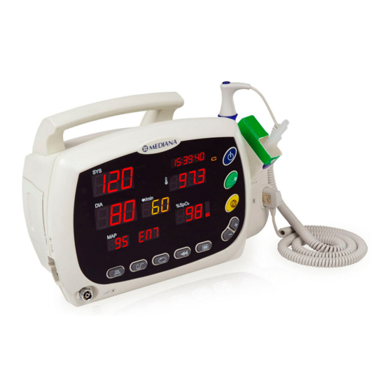
Page 31: Figure 8. Ym1000 Normal Mode Before Measurement
5. Upon successful completion of the POST, the monitor is blanked and enters Normal mode. Figure 8. YM1000 Normal Mode Before Measurement Note: If the segment of ‘SYS’, ‘DIA’ and ‘MAP’ displays is blinking, do not use the monitor and contact qualified service personnel or Mediana Technical Services Department because this symptom indicates that an internal problem may occur. Operator’s Manual YM1000... -
Page 32: Setting Date And Time
YM1000 Using the Monitor Setting Date and Time This procedure will enable you to set current date and time of monitor. YM1000 Note: The date format may be selected either ’year/month/day’ or ’day/month/year’ via Service mode. With the monitor in the normal monitoring mode: 1. Press and hold the Mode button for 3 seconds or more until the monitor enters Configuration mode. 2. Press the Mode button twice until the Time indicator and Hour set are flashing. Set current time to increment Hour up and down between 0 and 23, using the Up/Down (+/‐) selection buttons. 3. Press the Mode button until the Time indicator and Minute set are flashing. Set current minute between 00 and 59, using the Up/Down (+/‐) selection buttons. 4. Press the Mode button until the Time indicator and Second set are flashing. Set current second between 00 and 59, using the Up/Down (+/‐) selection buttons. 5. Press the Mode button until the Date indicator and Year set are flashing. Set current year, using the Up/Down (+/‐) selection buttons. ... -
Page 33: Setting Patient Type
YM1000 Using the Monitor Setting Patient Type This procedure will allow you to select Patient Type: Adult, Pediatric or Neonatal of monitor. YM1000 With the monitor in the normal monitoring mode: 1. Press the Mode button until the Patient type indicators are on (a selected Patient type indicator is shown flashing). 2. Select a desired patient type, using the Up/Down (+/‐) selection buttons. 3. Press any other button to return to normal operation. If there is no activity for 3 seconds, the monitor will return to normal operation. ... -
Page 34: Setting Nibp Units
YM1000 Using the Monitor Setting NIBP Units This procedure will allow you to select a NIBP measurement unit either mmHg or kPa. With the monitor in the normal monitoring mode: 1. Press and hold the Mode button for 3 seconds or more until the monitor enters Configuration mode. Once the monitor is in the Configuration mode, current NIBP unit is flashing on the display. 2. Select a NIBP unit either mmHg or kPa, using the Up/Down (+/‐) selection buttons. 3. Press any other button to return to normal operation. If there is no activity for 3 seconds, the monitor will return to normal operation. ... -
Page 35: Setting Temperature Units And Modes
YM1000 Using the Monitor Setting Temperature Units and Modes This procedure will allow you to set temperature type and measurement units of YM1000 with temperature option. You may select a temperature measurement unit either Celsius (°C) or Fahrenheit (°F) to be displayed. Also you may select whether to use Monitor mode or Predictive mode for taking temperatures. For more information, refer to page 49 in Temperature Monitoring section of this manual. With the monitor in the normal monitoring mode: 1. Press the Mode button until the Temperature units and modes are on (a selected unit/mode is shown flashing). 2. Select desired temperature unit and mode, using the Up/Down (+/‐) selection buttons. Fahrenheit Predictive (F) Fahrenheit Monitored (F M) Celsius Predictive (C) Celsius Monitored (C M) 3. Press any other button to return to normal operation. If there is no activity for 3 seconds, the monitor will return to normal operation. ... -
Page 36: Setting Pulse Tone Volume
YM1000 Using the Monitor Setting Pulse Tone Volume This procedure will enable you to set Pulse Tone Volume of monitor. YM1000 With the monitor in the normal monitoring mode: 1. Press the Mode button until the Pulse Tone Volume setting indicator and current pulse tone volume are displayed. 2. Select a level of pulse tone volume between 0 and 8, using the Up/Down (+/‐) selection buttons. 3. Press any other button to return to normal operation. If there is no activity for 3 seconds, the monitor will return to normal operation. Figure 13. Pulse Tone Volume Setting Operator’s Manual YM1000... -
Page 37: Setting Alarm Volume
YM1000 Using the Monitor Setting Alarm Volume This procedure will enable you to set audible Alarm Volume of monitor. YM1000 With the monitor in the normal monitoring mode: 1. Press the Mode button until the Alarm Volume setting indicator and current alarm volume are displayed. 2. Select a level of alarm volume between 1 and 8, using the Up/Down (+/‐) selection buttons. 3. Press any other button to return to normal operation. If there is no activity for 3 seconds, the monitor will return to normal operation. Figure 14. Alarm Volume Setting Operator’s Manual YM1000... -
Page 38: Resetting To Factory Defaults
YM1000 Using the Monitor Resetting to Factory Defaults Following procedure will allow you to reset the monitor operating parameters to the factory default settings. With the monitor powered off: 1. Simultaneously press the Power button and the NIBP start/stop button. 2. The monitor runs a self‐test and then displays the current monitor software version. 3. Press the Mode button until “ DEFAULT RESET=NO” is displayed. 4. To leave the settings unchanged, select ‘NO’ using only the Down (‐) selection button. To reset the operating parameters to the factory default values, select ‘YES’ using only the Up (+) selection button. The monitor immediately resets to the defaults and the confirmation tone sounds. 5. To return to normal operation, turn the monitor off; then restart. Figure 15. Factory Defaults Setting ... -
Page 39: Nibp Monitoring
WARNING: YM1000 displays results of the last blood pressure measurement until another measurement starts. If a patient’s condition changes during the time interval between measurements, YM1000 will not detect the change or indicate an alarm condition. ... -
Page 40: General
YM1000 NIBP Monitoring WARNING: As with all automatically inflatable blood pressure devices, continual cuff measurements can cause injury to the patient being monitored. Weigh the advantages of frequent measurement and/or use of STAT mode against the risk of injury. ... -
Page 41: Setup Connections
YM1000 NIBP Monitoring Setup Connections Figure 16. NIBP Setup Connections For the safety of patients, and to ensure the best product performance and accuracy, use only the cuffs and the hose provided with or recommended by Mediana Technical Services. YM1000 1. Measure the patient’s limb and select the proper size cuff. As a general rule, cuff width should span approximately two‐thirds of the distance between the patient’s elbow and shoulder. Follow cuff directions for use for applying the cuff to the arm. 2. Connect the hose to the bottom of left corner of the monitor as shown Figure 16. Table 5. Cuff Size Cuffs Circumference Range Neonate Cuff No.11 5.0 – 7.5 (cm) Cuff No.12 7.5 – 10.5 (cm) Cuff No.13 8.5 – 13.0 (cm) Pediatric HEM‐CS23 13.0 – 22.0 (cm) ... -
Page 42: Nibp Measurement Modes
YM1000 NIBP Monitoring NIBP Measurement Modes Blood pressure measurements can be made in three modes: MANUAL mode One measurement of each systolic/diastolic/mean arterial pressure. Automatic (AUTO) mode Measurements at preset intervals. STAT mode As many measurements as possible within a 5‐minute period. Description of NIBP Operation Setting Initial Inflation Pressure With the monitor in the normal monitoring mode: 1. Press the Mode button twice until current NIBP target inflation is displayed. 2. Change NIBP target inflation to be desired, using the Up/Down (+/‐) selection buttons. 3. Press any other button to return to normal operation. If there is no activity for 3 seconds, the monitor will return to normal operation. The numeric display in the lower right corner of the NIBP frame indicates the setting of the initial inflation pressure. The initial inflation pressure can be set from 120 to 260mmHg for ... -
Page 43: Figure 17. Initial Inflation Pressure
YM1000 NIBP Monitoring Figure 17. Initial Inflation Pressure Operator’s Manual YM1000... -
Page 44: Figure 18. Manual Mode Of Nibp Operation
YM1000 NIBP Monitoring Initiating MANUAL mode of NIBP operation 1. Press, momentarily, the NIBP start/stop button. A single blood pressure measurement will be made. As soon as an NIBP measurement begins, the SYS display dynamically shows the current cuff pressure. Systolic, diastolic, and MAP values are presented when the measurement is completed. The measurements remain in the numeric display for 2 minutes or until another NIBP cycle begins. Systolic Diastolic MAP Figure 18. Manual mode of NIBP operation Initiating AUTO mode of NIBP operation 1. Press the Auto button. The latest selected interval is displayed. ... -
Page 45: Figure 20. Auto Mode Setting (I.e.) – 15 Minute Period
YM1000 NIBP Monitoring The AUTO indicator is flashing when s selected for the automatic mode interval. After the first cycle, the cuff target pressure is not used; rather, the cuff inflates to a pressure level 20~30 mmHg above the previous systolic reading. The automatic NIBP cycles continue until one of the following occurs: The monitor reaches the 5‐minute limit for a STAT measurement. he monitor halts because the NIBP start/stop button is pressed. The monitor halts because the Auto button is pressed. The monitor halts because of an alarm, alert, or error condition. The AUTO cycle is changed to ‘‐’. Note: During Auto mode, if an NIBP limit violation alarm occurs, this alarm disables any automatic NIBP measurement until the alarm is released. Figure 20. Auto Mode Setting (i.e.) – 15 minute Period Note: The interval is the time from the beginning of one measurement cycle to the beginning of the next measurement cycle. Note: The selected interval is displayed on the Auto cycle display. The countdown timer for initiating next measurement is displayed on the Time display. Figure 21. Auto Mode of Measurement ... -
Page 46: Figure 22. Stat Mode Setting
YM1000 NIBP Monitoring Initiating STAT mode of NIBP operation 1. Press the Auto button. The latest selected interval is displayed. 2. Press the Up/Down (+/‐) selection buttons to set STAT. Upon selection, automatic measurement is activated and the initial measurement will be made in 3 seconds after you select an interval. Figure 22. STAT Mode Setting With the selected interval STAT, the monitor takes repeated NIBP measurements for 5 minutes. Current cuff pressures are not dynamically displayed during a STAT reading. The measurement displays the NIBP reading from the previous cycle until the current cycle ... - Page 47 YM1000 NIBP Monitoring This page is intentionally left blank. Operator’s Manual YM1000...
-
Page 49: Spo2/Pulse Rate Monitoring
there is excessive illumination from light sources such as a surgical lamp, a bilirubin lamp, or sunlight a blood pressure cuff is inflated on the same extremity as the one to which an sensor is attached WARNING: Do not attach any cable to the sensor port (sensor connector) that is intended for computer use. Operator’s Manual YM1000... -
Page 50: General
Refer to sensor directions for use. CAUTION: To ensure the best product performance and accuracy, use only Mediana provided SpO sensors for SpO measurements. Other SpO sensors may cause improper ... -
Page 51: Setup Connections
YM1000 /Pulse Rate Monitoring Setup Connections Use only provided sensor pulse oximetry cables and SpO sensors with . YM1000 Biocompatibility testing has been conducted on sensors in compliance with ISO10993‐1, Biological Evaluation of Medical Devices, Part 1: Evaluation and Testing. The sensors have passed the recommended biocompatibility testing and are therefore in compliance with ISO10993‐1. When selecting a sensor, consider patient’s weight and activity, adequacy of perfusion, ... -
Page 52: Description Of Pulse Rate Operation
YM1000 /Pulse Rate Monitoring Description of Pulse Rate Operation The monitor displays the pulse rate during SpO measurements. It displays NIBP pulse information only if no SpO reading is available. During the measurement period, the pulse amplitude indicator rises and falls in rhythm with the monitored pulse rate. The pulse amplitude indicator is a segmented display showing the relative strength of the detected pulse. As the detected pulse becomes stronger, more bars light with each pulse. Pulse Rate Figure 24. Pulse Rate Operation Description of SpO Operation Operation SpO2 & Pulse Amplitude Indicator ... - Page 53 YM1000 /Pulse Rate Monitoring Functional versus Fractional Saturation This monitor measures functional saturation — oxygenated hemoglobin expressed as a percentage of the hemoglobin that can transport oxygen. It does not detect significant amounts of dysfunctional hemoglobin, such as carboxyhemoglobin or methemoglobin. In contrast, hemoximeters such as the IL482 report fractional saturation — oxygenated ...
- Page 54 YM1000 /Pulse Rate Monitoring This page is intentionally left blank. Operator’s Manual YM1000...
-
Page 55: Temperature Monitoring
Temperature Monitoring General Setup Connections Temperature Measurement Modes Description of Temperature Operation WARNING: To avoid burns, the probe must remain in the probe well when turning YM1000 monitor on or off. WARNING: The monitor is intended only as an adjunct in patient assessment. It must be used in conjunction with clinical signs and symptoms. WARNING: To ensure patient safety and to obtain accurate and reliable temperature results, read this section thoroughly before using the temperature instrument. ... -
Page 56: General
YM1000 Temperature Monitoring General This section applies if the monitor is configured with the temperature option. Measurement of patient temperature is accomplished by processing the signal from a probe containing a resistance element whose impedance is temperature dependent. These devices are called thermistors. The signal from the probe is conditioned by the monitor input circuitry, processed, and the measured values are shown in the numeric frame. Setup Connections WARNING: To limit patient cross‐contamination, use only manufacturer’s recommended single‐use disposable probe covers. The use of any other probe cover, or the failure to use a probe cover, can endanger patients in the electrical risk point of view and produce inaccurate temperature measurements. Figure 26. Temperature Setup Connections Follow the directions for use accompanying the temperature probe. Note: Use only provided temperature probes which have passed the recommended biocompatibility testing in compliance with ISO10993‐1. Note: If temperature probes are not readily available, contact Mediana sales department. To avoid nuisance limit alarms, the probe should be affixed to the patient before connecting to right panel connector. YM1000 ... -
Page 57: Temperature Measurement Modes
YM1000 Temperature Monitoring Temperature Measurement Modes Temperature measurements can be made in two modes: PREDICTIVE mode is a one‐time measurement that takes only a few seconds. It results in a single temperature reading which is displayed at the end of the brief measurement period. MONITORED mode is a continuous measurement over an indefinite period. The current temperature displayed dynamically throughout the measurement period. Description of Temperature Operation Setting the Temperature Measurement Mode For the setting the Temperature measurement mode, you may refer to page 29, of this manual. 1. Press the Mode button until the Temperature units and modes are on (a selected unit/mode is shown flashing). 2. Select desired temperature unit and mode, using the Up/Down (+/‐) selection buttons. Note: If there is no activity for 3 seconds, the monitor will return to normal operation. Table 7. Indication of Temperature Measurement Mode Indication Temperature Mode Celsius Predictive ... -
Page 58: Figure 27. Temperature – Predictive Mode
YM1000 Temperature Monitoring Taking a Predictive Measurement To take a predictive temperature (Celsius Predictive or Fahrenheit Predictive indicator shall be on), follow these steps: Note: Verify that the temperature measurement type is set to predictive. (Indicator ‘M’ is not illuminated.) Temperature ‐ Predictive Mode (i.e. Celsius) Figure 27. Temperature – Predictive Mode Oral Measurement 1. Remove the temperature probe from the probe well. The temperature probe runs a self‐test, displaying ‘888.8’ for a few seconds. When it is ready for use, verify “OrL” appears in the temperature display. If not, press the Up/Down (+/‐) selection buttons to select Oral or Axillary. 2. Put a new probe cover on the probe tip. Verify that the cover locks into position. 3. Insert the tip of the probe into the mouth—under the tongue and against a sublingual pocket. 4. Hold the probe in place until the measurement is complete. When the temperature prediction is complete (usually about 10 seconds later), the monitor briefly sounds a tone and displays the temperature reading, which persists for one minute. Note: Use only a blue‐capped probe for oral temperatures. ... - Page 59 YM1000 Temperature Monitoring Axillary Measurement 1. Remove the temperature probe from the probe well. The temperature probe runs a self‐test, displaying ‘888.8’ for a few seconds. When it is ready for use, verify “ALY” appears in the temperature display. If not, press the Up/Down (+/‐) selection buttons to select Oral or Axillary. 2. Put a new probe cover on the probe tip. Verify that the cover locks into position. Note: Use only a blue‐capped probe for axillary temperatures. Note: During the measurement period, the temperature window displays a “walking box”—a box with the sides illuminated sequentially. When the measurement is complete, the monitor sounds a tone and displays the measurement in the temperature window. Note: Be sure that nothing touches the probe tip before you place it in the axillary measurement site. If the probe tip is moved after it first makes contact, the measurement is unreliable. 3. Lift the patient’s arm to fully expose the axilla. 4. Place the probe tip as high as possible in the axilla, and then bring the patient’s arm down to make maximum contact with the probe tip. Hold the patient’s arm in this position, keeping the patient as still as possible, for the duration of the measurement. When the temperature prediction is complete (usually about 10 seconds later), the monitor briefly sounds a tone and displays the temperature reading, which persists for one minute. 5. Eject the probe cover by pressing the ejection button, and hygienically dispose of it. 6. Return the probe into the probe well. ...
- Page 60 YM1000 Temperature Monitoring Rectal Measurement 1. Remove the temperature probe from the probe well. The temperature probe runs a self‐test, displaying ‘888.8’ for a few seconds. When it is ready for use, the monitor clears the temperature display. “rEC” appears in the temperature display. 2. Load a probe cover onto the probe. 3. Apply a thin coat of water‐based lubricant to the probe tip. 4. Separate the patient’s buttocks with one hand. 5. Insert the probe tip 1 centimeter (3/8‐inch) inside the rectal sphincter. Tilt the probe slightly to ensure good tissue contact, and keep the buttocks separated throughout the duration of the measurement. When the temperature prediction is complete (usually about 10 seconds later), the monitor briefly sounds a tone and displays the temperature reading, which persists for one minute. Note: Use only a red‐capped probe for rectal temperatures. Note: During the measurement period, the temperature window displays a “walking box”—a box with the sides illuminated sequentially. When the measurement is complete, the monitor sounds a tone and displays the measurement in the temperature window. 6. Remove the probe. 7. Eject the probe cover by pressing the ejection button, and hygienically dispose of it. ...
-
Page 61: Figure 28. Temperature – Monitored Mode
YM1000 Temperature Monitoring Taking a Monitored Measurement To take a predictive temperature (Celsius Monitored or Fahrenheit Monitored indicator shall be on), the procedures for monitored and predictive temperature measurements are the same, with the following exceptions: For monitored measurements: The monitor must be set to take a monitored temperature. The monitor displays the temperature continuously. The measurement continues until the probe is replaced in the probe well. Note: Verify that the temperature measurement type is set to monitored. If the measured temperature remains below the minimum measurable temperature for 5 minutes, the temperature cycle is terminated and the temperature display goes blank. To reactivate the probe, insert it into the probe well with disregarding a used probe cover and extract it again with loading a new probe cover. Temperature ‐ Monitored mode (i.e. Celsius) Figure 28. Temperature – Monitored Mode Note: The monitor only displays 26°C to 43°C (80°F to 110°F). If the reading is over 43°C (110°F) or under 26°C (80°F), the monitor will display as follows. Figure 29. Example display of over 43°C or under 26°C ... - Page 62 YM1000 Temperature Monitoring Probe Decontamination Procedure 1. Turn the monitor off. 2. Unplug the latching probe connector from the monitor. 3. Remove the probe from the probe well. 4. Remove the probe well from the monitor. 5. Clean the probe and the inner and outer surface of the probe well by swabbing with a cloth dampened with 70% isopropyl alcohol or a 10% solution of chlorine bleach. Note: Do not immerse or soak the probe in any type of fluid. Note: Do not autoclave the probe. Note: Do not use steam, heat, or gas sterilization of the probe or probe well. Note: Do not use hard or sharp objects to clean the probe well. Hard or sharp objects can damage the probe well, which could cause the unit to fail. Note: Do not autoclave the probe well. 6. Thoroughly dry all surfaces before reassembling the instrument. 7. Reinstall the probe well in the monitor. 8. Insert the probe into the probe well. ...
-
Page 63: Alarms And Limits
CAUTION: For patient safety, all alarms are reset to the factory default levels whenever the patient type is changed. This means that you must either accept the default alarm limits or set new limits every time you change patient type. CAUTION: The high alarm limit for any vital sign is always higher than the low alarm limit for the same vital sign. For example, the alarm limit for systolic high is always higher than the alarm limit for systolic low. Note: For adjusting alarm volume, you may refer to page 31, of this manual. Alarm volume is set to ‘4’ as a factory default. General When the monitor detects certain conditions that require user attention, such as out‐of‐ limit vital signs, monitor enters an alarm state. The monitor response is indicated YM1000 by visual and audible indication Table 8. Alarm Indication Alarm Condition Alarm Indication Battery Failure Presenting appropriate error codes and sounding audible alarms. Loss of Pulse Note: In case of loss of pulse alarm, error code (E44) is flashing Flashing the violating value in the appropriate display and Limit violation sounding audible alarms. Other system or Presenting appropriate error codes and sounding audible measurement error alarms if available. Operator’s Manual YM1000... -
Page 64: Setting Alarm Limits
YM1000 Alarms and Limits Setting Alarm Limits During patient monitoring, an alarm occurs when a measurement falls outside the programmed alarm limit. Alarms can be set or turned off for the following vital signs: Systolic high and Systolic low alarm limits Diastolic high and Diastolic low alarm limits MAP high and MAP low alarm limits Pulse rate high and Pulse rate low alarm limits high and SpO low alarm limits The range of high and low alarm limits for each vital sign is shown here: Table 9. Range of Alarm Limits (Defaults) Parameter Low Limit, Default High Limit, Default Resolution Systolic (mmHg) Neonatal 40 to 115, 50 45 to 120, 100 5 mmHg (0.7 kPa) Pediatric 60 to 155, 75 65 to 160, 145 5 mmHg (0.7 kPa) Adult 60 to 245, 75 65 to 250, 220 5 mmHg (0.7 kPa) Diastolic (mmHg) ... -
Page 65: Figure 30. Systolic High Alarm Limit Setting
YM1000 Alarms and Limits NIBP Alarm Limits Alarm Limits determine the high and low points of patient data at which the monitor will sound an alarm. Systolic high and low alarm limits With the monitor in the normal monitoring mode: 1. Press the Alarm button until Systolic high alarm limit is displayed. 2. Leave the limit unchanged or press the Up/Down (+/‐) selection buttons as needed to change the limit to another value. 3. Press the Alarm button once again until Systolic low alarm limit is displayed. 4. Leave the limit unchanged or press the Up/Down (+/‐) selection buttons as needed to change the limit to another value. Figure 30. Systolic High Alarm Limit Setting Figure 31. Systolic Low Alarm Limit Setting Operator’s Manual... -
Page 66: Figure 32. Diastolic High Alarm Limit Setting
YM1000 Alarms and Limits Diastolic high and low alarm limits With the monitor in the normal monitoring mode: 1. Press the Alarm button until Diastolic high alarm limit is displayed. 2. Leave the limit unchanged or press the Up/Down (+/‐) selection buttons as needed to change the limit to another value. 3. Press the Alarm button once again until Diastolic low alarm limit is displayed. 4. Leave the limit unchanged or press the Up/Down (+/‐) selection buttons as needed to change the limit to another value. Figure 32. Diastolic High Alarm Limit Setting Figure 33. Diastolic Low Alarm Limit Setting Operator’s Manual YM1000... -
Page 67: Figure 34. Map High Alarm Limit Setting
YM1000 Alarms and Limits MAP high and low alarm limits With the monitor in the normal monitoring mode: 1. Press the Alarm button until MAP high alarm limit is displayed. 2. Leave the limit unchanged or press the Up/Down (+/‐) selection buttons as needed to change the limit to another value. 3. Press the Alarm button once again until MAP low alarm limit is displayed. 4. Leave the limit unchanged or press the Up/Down (+/‐) selection buttons as needed to change the limit to another value. Figure 34. MAP High Alarm Limit Setting Figure 35. MAP Low Alarm Limit Setting Operator’s Manual YM1000... -
Page 68: Figure 36. Pulse Rate High Alarm Limit Setting
YM1000 Alarms and Limits Pulse Rate Alarm Limits Alarm Limits determine the high and low points of patient data at which the monitor will sound an alarm. With the monitor in the normal monitoring mode: 1. Press the Alarm button until Pulse rate high alarm limit is displayed. 2. Leave the limit unchanged or press the Up/Down (+/‐) selection buttons as needed to change the limit to another value. 3. Press the Alarm button once again until Pulse rate low alarm limit is displayed. 4. Leave the limit unchanged or press the Up/Down (+/‐) selection buttons as needed to change the limit to another value. Figure 36. Pulse Rate High Alarm Limit Setting Figure 37. Pulse Rate Low Alarm Limit Setting Operator’s Manual YM1000... - Page 69 YM1000 Alarms and Limits Alarm Limits Alarm Limits determine the high and low points of patient data at which the monitor will sound an alarm. With the monitor in the normal monitoring mode: 1. Press the Alarm button until SpO high alarm limit is displayed. 2 2. Leave the limit unchanged or press the Up/Down (+/‐) selection buttons as needed to change the limit to another value. 3. Press the Alarm button once again until SpO low alarm limit is displayed. 4. Leave the limit unchanged or press the Up/Down (+/‐) selection buttons as needed to change the limit to another value. Figure 38. SpO High Alarm Limit Setting Figure 39. SpO Low Alarm Limit Setting ...
-
Page 70: Alarm Silence
YM1000 Alarms and Limits Alarm Silence WARNING: Do not silence the audible alarm or decrease its volume if patient safety could be compromised. Press the Alarm Silence Button on the front panel. This action temporarily silences all audible alarms for 90 seconds. Alarm Silence Indicator lights during a temporary silence period. 1. Press the Alarm Silence Button to immediately silence the alarm tone. (Alarm silence period default‐90 seconds later, the alarm resumes if the alarm condition has not been corrected.) 2. Check the patient and provide appropriate care. If the Alarm Silence Button is pressed during the alarm silence, the alarm silence is ended and the audible alarms are re‐enabled. Note: Visual indications of an alarm condition cannot be turned off. For example, if the %SpO low alarm limit is exceeded, the audible alarm can be silenced for the alarm silence period, but the %SpO value will continue to flash. Note: Low Battery alarm cannot be silenced while running on battery power. Connecting the monitor to AC power will silence the alarm. If a sensor disconnect alarm is occurred, the alarm can be released by pressing the Alarm Silence Button. ... -
Page 71: Reviewing Patient Data
The next most recent stored data sets display wrapping from the first stored data set to the last by pressing the Review button subsequently. In Review mode, the readings show time of reading in minus time, for example, (‐0:05) is 5 minutes ago, (‐2:45) is 2 hour 45 minutes ago 2. Press the Up/Down (+/‐) selection button to cycle forward or backward (scroll) through the stored measurement data sets. (The monitor stores 200 measurement cycles.) 3. To stop reviewing data and return to normal operation, press any button other than the Review button or the Up/Down (+/‐) selection button. Operator’s Manual YM1000... -
Page 72: Figure 40. Stored Patient Data Display
YM1000 Reviewing Patient Data Data #1 Display: Data stored at an error occurred 2 minutes ago Data #2 Display: Data stored at the measurement completed 18 minutes ago Figure 40. Stored Patient Data Display Note: 5 seconds of operator inactivity will exit Review mode and return to Normal mode. Operator’s Manual YM1000... -
Page 73: Printing Stored Patient Data (Optional Printer Installed)
YM1000 Reviewing Patient Data Printing Stored Patient Data (Optional Printer Installed) You can print vital‐signs measurement data each time the monitor completes a measurement cycle (stream printing), or you can store patient data and then print all of it at one time (batch printing). For information on setting the printer for stream printing or batch printing, see “Printing section” on page 67. Follow the instructions to print stored data if an optional printer is installed. 1. Press Print button when the monitor is in Review mode to display stored data on the screen. If the monitor is not printing, press the Print button to start printing. If the monitor is printing, press the Print button to stop printing. Note: The print button is not enabled during an NIBP cycle. Erasing Patient Data All patient vital‐signs data is stored even the monitor is powered off, however 24‐hour old data will be removed. You can also erase patient data when you change the time and date settings and at any time during normal monitor operation. Erasing Data During Normal Operation To erase patient data during normal operation; 1. Press and hold the Review button for 3 seconds to erase data in the memory. After data cleared, the monitor returns to normal operation. Operator’s Manual... - Page 74 YM1000 Reviewing Patient Data This page is intentionally left blank. Operator’s Manual YM1000...
-
Page 75: Printing
Manual Mode The monitor prints out current measurement data (Real‐time printing) or stored patient data on the screen (Batch printing). Manual print indicator is on. Stream Mode The monitor automatically prints out patient measurement data: as NIBP measurement or Temperature predictive measurement completes. Also in Stream mode, the monitor automatically prints out the measurement data when an alarm condition occurs. When the Print button is pressed at Stream mode, the monitor prints out current measurement data. Stream print indicator is on. Selecting Manual or Stream Printing type This procedure will allow you to select Print mode either Manual or Stream. With the monitor in the normal monitoring mode: 1. Press and hold the Mode button for 3 seconds or more until the monitor enters Configuration mode. 2. Press the Mode button once again until either Manual Print or Stream Print indicator is flashing on the display. 3. Press the Up/Down (+/‐) selection button to alternate between Manual Print and Stream Print and display. A selected type indicator will be flashing on the display. 4. To set the displayed printing method and return to normal operation, press any other key. If there is no activity for 5 seconds, the monitor will return to normal operation. Figure 41. Printing Type Setting Operator’s Manual YM1000... -
Page 76: Printing Patient Data (Manual Mode)
YM1000 Printing Printing Patient Data (Manual Mode) You can print vital‐signs measurement data each time you press the Print button (Manual printing), or you can store patient data and then print all of it at one time (Batch printing). Follow the instructions to print stored data if an optional printer is installed. 1. Press Print button when the monitor is in Normal or Review mode. If the monitor is not printing, press the Print button to start printing. If the monitor is printing, press the Print button to stop printing. Note: The print button is not enabled during an NIBP cycle. Note: The monitor sounds an invalid button tone when the printer door opens or when paper runs out. Operator’s Manual YM1000... -
Page 77: Print Out Configuration
YM1000 Printing Print Out Configuration Print Out includes information as follows: Header: Time, Date, Measurement Parameters and Parameter units Measurement data and/or error codes Real Time Print Out at Manual and Stream Modes Patient Name: Patient ID: Physician: Comments: TIME SYS DIA MAP HR O TEMP ‐ ‐ mmHg ‐ ‐ BPM % °C 17:26 26‐Mar‐2004 17:26 127 84 98 68 98 36.1 Figure 42. Real‐Time Printing Stored Data Print Out Patient Name: Patient ID: Physician: Comments: TIME SYS DIA MAP HR O TEMP ... -
Page 78: Figure 44. Stream Printing At Alarm Condition
YM1000 Printing Stream Print Out at Alarm Condition Patient Name: Patient ID: Physician: Comments: TIME SYS DIA MAP HR O TEMP ‐ ‐ mmHg ‐ ‐ BPM % °C 17:52 26‐Mar‐2004 17:52 127 84 98 200↑ 75 36.1 Figure 44. Stream Printing at Alarm Condition System Information Print out If the Print button is pressed while the monitor is in Service mode only accessed by qualified authorized personnel, the monitor prints out the internal settings of the monitor as shown in Figure 45. 17:52 26‐Mar‐2004 Patient type: Adult NIBP target press (mmHg): 160 NIBP auto interval: 15 NIBP units: ... -
Page 79: Rs-232 Interface
RS-232 Interface Overview Cable Connection Nurse Call Interface Overview monitor provides RS‐232 I/O port for software upgrade or nurse call system. The 9‐ YM1000 pin connector mounted on the rear panel provides an access port for a serial interface. RS‐ 232 I/O port is intended only for connection to specified equipment in accordance with compliance requirements. Cable Connection Figure 46. RS‐232 I/O connector The Pin layouts (as viewed from the rear panel of ) are illustrated below. YM1000 Figure 47. Data Port Pin Layout Table 10. RS‐232 Serial Interface Connections Pin # Signal 1 +5V (Use for Software Upgrade) 2 RxD_232 (RS‐232 Input) 3 TxD_232 (RS‐232 Output) 4 DTR (Use for Software Upgrade) 5 ... -
Page 80: Nurse Call Interface
YM1000 RS-232 Interface Nurse Call Interface WARNING: Although the Nurse Call option enables remote notification of an alarm condition, it is not intended to replace appropriate bedside patient surveillance by trained clinicians. The monitor can be connected to a Nurse Call system through a customized cable that connects to the Nurse Call connector. When the cable is connected and operational, the monitor immediately notifies the Nurse Call system when a patient alarm occurs. The Nurse Call function specification is as follows: Switch current: 1 A maximum Switch voltage: 30 Vac/dc maximum Isolation: 1500 Vrms Alarm relay: Normal open (default) Note: The alarm relay may be selected either ’Normal Open’ or ’Normal Close’ via Service mode. Operator’s Manual YM1000... -
Page 81: Quick Guide To Operation
Quick Guide to Operation Operator’s Manual YM1000... - Page 82 YM1000 Quick Guide to Operation Operator’s Manual YM1000...
- Page 83 YM1000 Quick Guide to Operation Operator’s Manual YM1000...
- Page 84 YM1000 Quick Guide to Operation Operator’s Manual YM1000...
- Page 85 YM1000 Quick Guide to Operation Operator’s Manual YM1000...
- Page 86 YM1000 Quick Guide to Operation Operator’s Manual YM1000...
-
Page 87: Maintenance
Maintenance General Returning YM1000 and System Components Service Periodic Safety Checks Cleaning Battery Maintenance Replacement of Printer Paper WARNING: Only qualified service personnel should remove the cover. There are no internal user‐serviceable parts. WARNING: Do not spray, pour, or spill any liquid on YM1000 vital signs monitor, its accessories, connectors, switches, or openings in the chassis. CAUTION: Unplug the power cord from the monitor before cleaning the monitor. ... -
Page 88: Periodic Safety Checks
YM1000 Maintenance Periodic Safety Checks It is recommended that the following checks be performed every 24 months. Inspect the equipment for mechanical and functional damage. Inspect the safety relevant labels for legibility. Cleaning For surface‐cleaning, follow your institution’s procedures or: may be surface‐cleaned by using a soft cloth dampened with either a YM1000 commercial or nonabrasive cleaner, and lightly wiping the top, bottom, and front surfaces of the monitor lightly. For sensors and probes follow cleaning, disinfecting and/or sterilizing instructions in the directions for use shipped with those components. Never allow any liquid substance to enter any monitor connector. If a connector does come in contact with a liquid substance accidentally, clean and dry thoroughly before reuse. If in doubt about monitor safety, refer the unit to qualified service personnel. Battery maintenance If vital signs monitor has not been used 2 months, the battery will need charging. To YM1000 charge the battery, connect to an AC power source as described in the Battery YM1000 Operation section. Note: Storing for a long period without charging the battery may degrade the battery YM1000 capacity. A full charge of a dead battery takes approximately 12 hours while the ... -
Page 89: Replacement Of Printer Paper
YM1000 Maintenance Replacement of Printer Paper 1. Open the door by pulling the latch on the printer slightly. The door should tilt open. 2. Reach in and remove the spent paper core by pulling it over gently with your thumb and index finger. 3. Place a new paper roll. Orient the paper roll. 4. Pull the paper towards you until approximately 2 inches (5.08 cm) of paper have been unrolled. 5. Align the paper with the pinch roller attached to the printer door. 6. Close the printer door. Note: To ensure that the paper is aligned in the slot and has not been pinched in the door, pull the loose edge until a few inches of paper is showing. If the paper will not move, open the door and return to alignment step 5. Note: The monitor sounds an invalid button tone when the printer door opens or when paper runs out. Operator’s Manual YM1000... - Page 90 YM1000 Maintenance This page is intentionally left blank. Operator’s Manual YM1000...
-
Page 91: Troubleshooting
WARNING: If you are uncertain about the accuracy of any measurement, check the patient’s vital signs by alternate means; then make sure the monitor is functioning correctly. WARNING: Only qualified service personnel should remove the cover. There are no user‐serviceable parts inside. CAUTION: Do not spray, pour, or spill any liquid on YM1000, its accessories, connectors, switches, or openings in the chassis. General If is unable to perform any of its monitoring functions because of the loss of software YM1000 control a detected hardware malfunction, an error code is presented. ... -
Page 92: Corrective Action
YM1000 Troubleshooting Serviceable error codes and other error codes are listed in service manual. If the YM1000 monitor continues to present an error code, call the Mediana technical representative and report the error code number. You will be advised of the remedial action to be taken. Before calling the Mediana Technical Services Department, make sure that the battery is charged, and that all power connections are correctly made. Corrective Action If you experience a problem while using and are unable to correct it, contact qualified YM1000 service personnel or Mediana Technical Services Department. service manual, which is for user by qualified service personnel, provides additional YM1000 troubleshooting information. Following is a list of possible errors and suggestions for correcting them. 1. There is no response to the Power On/Off switch. A fuse may be blown. Notify service personnel to check and, if necessary, replace the fuse. If operating on battery power, the battery may be missing or discharged. If the battery is discharged, charge the battery, see Battery Operation section. 2. The monitor display does not function properly and the power‐on beep tones do not sound during the power‐on self‐test. Do not use ; contact qualified service personnel or Mediana Technical Services ... -
Page 93: Emi (Electromagnetic Interference)
WARNING: It is possible, although unlikely, that large equipment using a switching relay for its power on/off may result in disruption of performance of YM1000 when the large equipment powers on or off. Do not place YM1000 to monitor in such environments. CAUTION: This device has been tested and found to comply with the limits for medical ... -
Page 94: Obtaining Technical Assistance
YM1000 Troubleshooting Obtaining Technical Assistance For technical information and assistance, or to order an service manual, call Mediana YM1000 Technical Services Department. The service manual includes information required by qualified service personnel when servicing . YM1000 When calling Mediana Technical Services Department, you may be asked to tell the representative the software version number of your . Qualified service personnel or YM1000 Mediana Technical Services Department may help you check the software version installed in your monitor. Operator’s Manual YM1000... -
Page 95: Factory Defaults
Factory Defaults General Parameter Ranges and Default Settings General is shipped with factory default settings. You may change the default settings to YM1000 desired values as described in ‘Using the Monitor’ and ‘Alarm and Limits’ sections of this manual. When you turn the monitor off properly with the change of the default setting, the changed settings will be saved and they will be power‐on default settings for next power‐on. If you want the power‐on setting back to factory defaults, refer to page 32 ‘Using the Monitor’ section of this manual. Parameter Ranges and Default Settings Table 12. Parameter Ranges and Factory Defaults Parameter Ranges Defaults Systolic (mmHg) Neonatal Low: 40 to 115 High: 45 to 120 50, 100 Alarm Limits Pediatric Low: 60 to 155 High: 65 to 160 75, 145 Adult Low: 60 to 245 ... - Page 96 YM1000 Factory Defaults This page is intentionally left blank. Operator’s Manual YM1000...
-
Page 97: Specifications
Physical Instrument Dimensions 130×180×284 (mm) Weight 2.7 (kg) Electrical AC Power Power 100Vac to 240Vac, 50 Hz/60 Hz, 28 to 38 VA Battery Type Lead acid or Ni‐MH (option) Voltage/Capacity Lead acid : 6 V/ 4 Ampere‐Hours Ni‐MH : 8.4V/ 7.6 Ampere‐Hours (option) Charging time 12 hours with YM1000 Shelf Life 2 years, new fully charged battery Complies with 91/157/EEC Environmental Operation Temperature 10 °C (50 °F) to 40 °C (104 °F) Exemption: thermometry module – operating temperature 16 °C (60 °F) to 40 °C (104 °F) Humidity 15 % RH to 95% RH, non‐condensing Altitude 170 m (557 ft) below sea level 4,877 m (16,000 ft) above sea level Transport and Storage Temperature –20 °C (‐4 °F) to 50 °C (122 °F) ... -
Page 98: Measurement Parameters
YM1000 Specifications Measurement Parameters NIBP Pulse Rate Pulse Rate Range Adult/Pediatric 40 BPM to 200 BPM Neonatal 40 BPM to 240 BPM Pulse Rate Accuracy ±2 BPM or ±2%, whichever is greater NIBP (Non‐Invasive Blood Pressure) Technique Oscillometric Measurement Measurement modes AUTO, MANUAL and STAT AUTO Mode Automatic NIBP measurements at intervals of 1, 2, 3, 4, 5, 10, 15, 30, 45, 60, 90, 120, and 240 minutes MANUAL Mode Single measurement initiated by NIBP Start/Stop switch STAT Mode Series of consecutive measurements for 5 minutes NIBP pressure measurement range Systolic pressure range Adult: 60 mmHg to 250 mmHg (8.0 kPa to 33.3 kPa) Pediatric: 60 mmHg to 250 mmHg (8.0 kPa to 33.3 kPa) Neonatal: 40 mmHg to 120 mmHg (5.3 kPa to 16.0 kPa) Diastolic pressure range Adult: 40 mmHg to 200 mmHg (5.3 kPa to 26.7 kPa) Pediatric: 40 mmHg to 200 mmHg (5.3 kPa to 26.7 kPa) Neonatal: 20 mmHg to 90 mmHg (2.7 kPa to 12.0 kPa) Mean pressure range Adult: 45 mmHg to 235 mmHg (6.0 kPa to 31.3 kPa) Pediatric: 45 mmHg to 235 mmHg (6.0 kPa to 31.3 kPa) Neonatal: 30 mmHg to 100 mmHg (4.0 kPa to 13.3 kPa) Pressure Display Accuracy Meets ANSI/AAMI SP10:2002+A1:2003 ... - Page 99 YM1000 Specifications /Pulse Rate %Saturation Range 1% to 100% Low Perfusion 0.03% to 20% Accuracy Without Motion‐Adults 70% to 100% ±2 digits 1% to 69% unspecified Without Motion‐Neonate 70% to 100% ±3 digits 1% to 69% unspecified Low Perfusion 70% to 100% ±2 digits 1% to 69% unspecified Pulse Rate Range 20 BPM to 300 BPM Accuracy Without Motion 20 BPM to 300 BPM ±3 digits Low Perfusion 20 BPM to 300 BPM ±3 digits Standards EN865:1997 Neonate specifications are shown for neonate sensors with YM1000. Saturation accuracy will vary by sensor type recommended by the manufacturer.. Specification applies to monitor performance and was validated with Biotek and Nellcor simulators Temperature Probe Type Thermistor probe Range 26° C to 43° C (80° F to 110°F) Display Accuracy ...
-
Page 100: Compliance
YM1000 Specifications Compliance Item Compliant with Classification Class I (on AC power) Internally powered (on battery power) Type of protection Type BF – Applied part General Safety 93/42/EEC Medical Device Directive 21CFS820 Code of Federal Regulations 91/157/EEC Battery Declaration Directive 93/86/EEC Battery Disposal Directive 2002/96/EC waste electrical and electronic equipment (WEEE) ISO9001:2000 Quality Management Systems‐Requirements ISO13485:2003 Quality Systems‐Medical Devices‐Particular requirements for the application of ISO9001 IEC60601‐1:1988+A1:1991+A2:1995 General requirements for Safety and Essential Performance IEC60529 Degree of Protection Provided by Enclosures Water Ingress Testing (IPX0) EN540:1993 Clinical Investigation of Medical Devices for Human Subjects EN ISO14155‐1:2003 Clinical Investigation of Medical Devices for Human Subjects‐part 1: General Requirement AAMI HE48:1993 Human factors engineering guidelines and preferred ... - Page 101 YM1000 Specifications Item Compliant with Electromagnetic IEC 60601‐1, sub clause 36, IEC/ Compatibility IEC60601‐1‐2:2001+A1:2004 Electromagnetic compatibility‐requirements & test IEC61000‐3‐2:2004 Harmonic Emission IEC61000‐3‐3:2002 Voltage Flusctuations/Flicker Emission IEC61000‐4‐2:2001 Electrostatic Discharge (ESD) IEC61000‐4‐3:2002 Radiatd RF electromagnetic field IEC61000‐4‐4:2004 Electrical fast Transient/Burst (EFT) IEC61000‐4‐5:2001 Surge current IEC61000‐4‐6:2004 Conducted disturbances, induced by RF field IEC61000‐4‐8:2001 Power frequency (50/60H) Magnetic field IEC61000‐4‐11:2004 Voltage dips, short interruptions, and vlotage variation on power supply input lines CISPR 11:1997 (EN55011:1998) RF Emissions Group 1, Class B Limits and methods of measurement of radio disturbance characteristics of industrial scientific and medical (ISM) radio‐frequency equipmen Labeling EN1041:1998 Information supplied by the manufacturer with medical devices Marking IEC /TR60878:2003 Graphical symbols for electrical equipment in medical practice EN980:2003 Graphical symbols for use in the labeling of medical devices ISO7000:2004 Graphical symbols for use on equipment‐index and synopsis EN60417‐1:1999 Graphical symbols for use on equipment‐overview and application EN60417‐2:1999 Graphical symbols for use on equipment‐symbol originals ...
-
Page 102: Manufacturer's Declaration
YM1000 Specifications Manufacturer’s Declaration WARNING: The use of accessories, transducers, and cables other than those specified may result in increased emission and/or decreased immunity of YM1000 monitor. is suitable for use in the specified electromagnetic environment. The customer YM1000 and/or user of should assure that it is used in an electromagnetic environment YM1000 as described below; Table 13. Electromagnetic Emissions (IEC60601‐1‐2) Emission Test Compliance Electromagnetic Environment RF emission Group 1 must emit electromagnetic energy YM1000 CISPR 11 in order to perform its intended function. Nearby electronic equipment may be affected. ... -
Page 103: Table 15. Electromagnetic Immunity (Iec60601-1-2)
YM1000 Specifications Immunity Test IEC60601‐1‐2 Test Compliance Electromagnetic Environment Level Level Guidance <5 % U T <5 % U T (95 % dip in UT ) (95 % dip in UT) for 5 sec. for 5 sec. Power 3 A/m 3 A/m It may be necessary to position frequency further from the YM1000 (50/ 60 Hz) sources of power frequency magnetic field magnetic fields or to install magnetic shielding. The power IEC 61000‐4‐8 frequency magnetic field should be measured in the intended installation location to assure that it is sufficiently low. Note: UT is the AC mains voltage prior to application of the test level. Table 15. Electromagnetic Immunity (IEC60601‐1‐2) ... -
Page 104: Table 16. Recommended Separation Distances
YM1000 Specifications Table 16. Recommended Separation Distances Frequency of 150kHz to 80MHz 80MHz to 800MHz 800MHz to 2.5GHz Transmitter Equation d = 1.2 √P d = 1.2 √P d = 2.3 √P Rated Maximum Separation Distance Separation Distance Separation Distance Output Power of in Meters in Meters in Meters Transmitter in Watts 0.01 0.12 0.12 0.23 0.1 0.38 0.38 0.73 1 1.2 1.2 2.3 10 3.8 3.8 7.3 100 12 12 ...
Need help?
Do you have a question about the YM1000 and is the answer not in the manual?
Questions and answers