ABB LLT100 Operating Instructions Manual
Laser level transmitter oi-llt100-en rev. d
Hide thumbs
Also See for LLT100:
- Operating instruction (4 pages) ,
- Functional safety manual (32 pages) ,
- User manual (18 pages)
Table of Contents
Advertisement
Operating Instructions/OI-LLT100-EN Rev. D
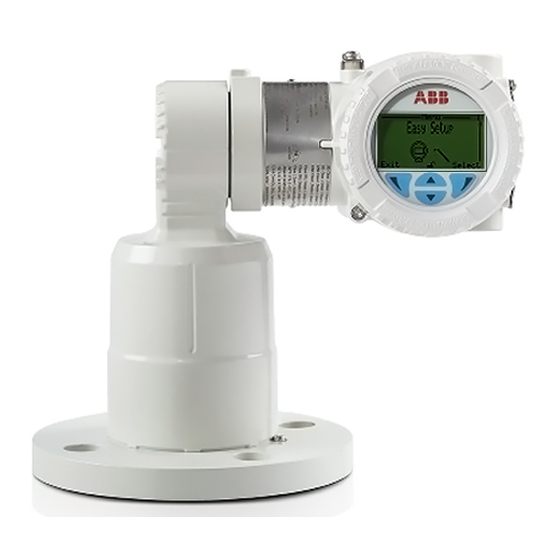
LLT100
Laser Level Transmitter
The new standard in industrial laser
level transmitters
Measurement made easy
Customer benefits
The LLT100 is specifically made for industrial applications
and harsh environments. It provides continuous, non-contact
level measurement capabilities for process automation
and inventory management in industries such as mining,
aggregates, oil & gas, chemicals, food & beverages, power,
pulp & paper, pharma, and water & waste water.
Optimize process or inventory management
– Precise measurement of any solid or liquid
– Independent of material properties
Low cost of ownership
– Fast and flexible installation
– No maintenance
– Single product configuration works in many applications
Main features
ABB brings laser level transmitters to the next level of non-
contact measurements by packaging laser ranging technology
with the features required by industrial applications. Using a
pulsed laser for performing time-of-flight measurements,
the LLT100 provides accurate distance measurements
while being powered from the 4 – 20 mA loop. Available in
aluminum or stainless steel body, it comes with a variety of
process interfaces. It can meet the demands of hazardous
area locations, as well as high pressure and high temperature
applications.
Convenient
– Easy setup function
– Articulated embedded user interface
– 2-wire powered, and HART 7 communication
Reliable
– Dust and fog penetration capabilities
– Accurate measurements at short and long distances
– Explosion-proof class 1, division 1 (zone 1)
Advertisement
Table of Contents

Related Manuals for ABB LLT100

Summary of Contents for ABB LLT100
-
Page 1: Main Features
Customer benefits Main features The LLT100 is specifically made for industrial applications ABB brings laser level transmitters to the next level of non- and harsh environments. It provides continuous, non-contact contact measurements by packaging laser ranging technology level measurement capabilities for process automation with the features required by industrial applications. - Page 2 ABB Inc. has been advised of the possibility of such damages. All equipment, software, and manuals are sold as is. The entire risk as to the results and performance of the equipment and software is assumed by the user.
-
Page 3: Table Of Contents
10.5 Managing process alarms settings ....30 Quick setup ............. 15 Introducing the default factory settings ..... 15 11 Installing the LLT100 on site ........31 Setting initial parameters with LCD interface ..16 11.1 Safety information ........... 31 11.2 General information ......... 31 Setting up general device parameters .... - Page 4 Dust tube ..............55 Purge ring ..............55 Adjustable pivot bracket ..........56 Swivel mount ............57 Specifications ............58 Appendix C Instrument specifications ...... 59 Appendix D EU Declaration of Conformity ....61 iv Operating Instructions | OI-LLT100-ENA Rev. D...
-
Page 5: Safety
ASER RADiAtioN The laser warning icon indicates the presence of a All obligations of ABB arise from the conditions of the relevant laser related hazard. It also indicates the type of laser sales agreement, which also contains the solely binding in use, its wavelength and its safety class. -
Page 6: Personnel
During installation, completely power down the Building Code, etc. 4–20 mA loop for at least 60 seconds, as otherwise it Since the LLT100 may form part of a safety chain, we may cause a permanent error. recommend replacing the device immediately if any defects are detected. -
Page 7: Laser
The LLT100 is designated as a Class 1 laser device during all WARNiNG oltAGE procedures of operation, as per IEC 60825-1, Ed. 2, 2007. It All protective earthing connections (grounding) must complies with FDA performance standards for laser products, be active at all times. The absence of grounding can except for deviations pursuant to Laser Notice No. - Page 8 This page intentionally left blank...
-
Page 9: Introducing The Llt100
Moreover, ABB declares that the contents of this manual are not part of any prior or existing agreements, This user guide is intended for personnel using the LLT100 commitments, or legal relationships, nor are they intended to for routine analysis; it contains installation, user, maintenance, amend these. - Page 10 This page intentionally left blank...
-
Page 11: Connecting The Llt100
(see “Typical connections” on page 10). Do NOT make electrical connections unless the – Since the LLT100 may form part of a safety chain, we electrical code designation stamped on the LLT100 data recommend replacing the device immediately if any defects plate matches the classification of the area in which you want to install the LLT100. -
Page 12: Connecting The Instrument
LLT100 Laser level transmitter The LLT100 has a ½-inch NPT/M20 cable gland entry. You must use a ½-inch NPT/M20 cable gland certified to either Unused electrical connection port Ex db or Ex tb (depending on the installation), and rated to at with standard metal cap least IP66/IP67. -
Page 13: Grounding The Instrument
3.4.2 Common mode voltages Protective earth (PE) terminals are available inside and outside The LLT100 with surge protection will not work if exposed to the instrument housing (see Figure 5 on page 9). These common mode voltage in excess of the maximum allowed terminals are electrically connected. -
Page 14: Powering On The Instrument
LLT100 Laser level transmitter Powering on the instrument Once the LLT100 has been connected, you energize it by turning on the power source. Before turning on the power source, check the following: – Covers’ installation – Locking screws tightness – Process connections –... -
Page 15: Presenting The User Interface
Typical User screen (left) and Configuration screen (right) 4.1 LCD interface and keypad Table 1: Left and Right arrow key functions The integrated LCD can be used to configure the LLT100 and Left arrow key ( Meaning to visualize process measured variables. -
Page 16: Navigating The User Interface
6. Press Back repeatedly to exit the menu. For more information on setting passwords, see “Protecting access with passwords” on page 19. NOTICE ABB recommends the Advanced setting as it provides the best balance of access and security. 12 User Guide | OI-LLT100-EN Rev. D... -
Page 17: Presenting The First Level Of Configuration Menus
LLT100 instruments. In case arrow key will navigate through the various menus in the of failure, the LLT100 instrument must be sent back to following order: ABB for calibration and repair. - Page 18 This page intentionally left blank...
-
Page 19: Quick Setup
The LLT100 can be configured with the integrated, keypad- controlled and menu-driven LCD user interface. The LLT100 is delivered with the following default settings: Before setting up your LLT100 instrument, it is important to Parameter Factory setting know which value is associated with which setting. Figure 15... -
Page 20: Setting Initial Parameters With Lcd Interface
Laser level transmitter Setting initial parameters with LCD interface 5.2.2 Setting volume parameters 1. Once the LLT100 is on, access Easy Setup in the Once you powered on the LLT100, you can set the basic configuration menus and press Select. - Page 21 Positioning This mode features a special calibration designed to work with Use for positioning applications where the sensor aims at a retroreflector panel targets provided by ABB. It also features an highly-reflective retroreflector panel. enhanced double-reflection detection algorithm. Note: Only use when the target is a retroreflector panel. For positioning applications with other types of targets, use the standard measurement mode.
- Page 22 This page intentionally left blank...
-
Page 23: Setting Up General Device Parameters
6.3 Setting measurement values You can set all device-specific parameters from the Device Setup configuration menu. The LLT100 can monitor four values. These values are identified as primary (PV), secondary (SV), tertiary (TV), and quaternary (QV). The primary value (PV) is the only value directly linked to the 4 –... -
Page 24: Setting Level Calibration Points
Configuring linearization When measuring a volume, changes in the measured volume are not linear in odd-shaped vessels. The LLT100 linearization function allows for conversion of a measure into a known Figure 17 Calibration points volume, regardless of vessel shape. -
Page 25: Setting The Level Offset
1. From the Device Setup menu, select Level Offset. 2. Edit the level offset and press OK. This offset will be applied The LLT100 filtering feature is designed to filter out data that to all measurements made in the vessel. - Page 26 This page intentionally left blank...
-
Page 27: Configuring Filtering
7 Configuring filtering The LLT100 filtering feature is designed stabilize measurements 7.2.2 Setting the No Measurement period by filtering out extraneous data that could negatively impact To do so: the resolution of the measured level (spikes, obstructions in 1. From the Device Setup menu, select Filtering > No the beam by mixer blades, lack of signal, etc.). -
Page 28: Configuring The Filling Rate
This rate must be set to the process maximum draining rate to avoid equipment (e.g., pumps) running on empty. The instrument sensor smooths out any change in level that is faster than the entered draining rate. 24 User Guide | OI-LLT100-EN Rev. D... -
Page 29: Configuring Linearization
8 Configuring linearization 8.1 Defining linearization 8.2 Configuring device linearization In the LLT100, the linearization function allows more accurate The linearization function, available only in Advanced mode, is volume measurements by referring to a preset linearization always used to convert level to volume in all applications. In table. -
Page 30: Managing Linearization Tables
To revert to the default linearization table: 1. From the Device Setup menu, select Linearization > Configure Tables > Reset. 2. From the Configure Tables screen, press OK. The linearization table is reset to its default empty setting. 26 User Guide | OI-LLT100-EN Rev. D... -
Page 31: Configuring The Display
7. (if necessary) Repeat steps 4 to 6 to configure all remaining values. The LLT100 screen can display any of four different Operator pages. Operator pages are intended to display relevant Below is an example of Operator page 2 in a 2×9 configuration information about ongoing process measurements. -
Page 32: Selecting The Number Of Decimals
To save display settings: Selecting the number of decimals 1. From the Display menu, select Settings > Save as default. The LLT100 allows you to set the number of decimals to 2. From the Save as default screen, press OK. display on screen. -
Page 33: Configuring Process Alarms
10.1 Setting failure mode 1. From the Process Alarm menu, select Alarm Delay. The LLT100 allows you to set which alarm value will trigger the 2. From the Alarm Delay screen, edit the length of time during failure mode (see “Setting measurement value high and low which an alarm can persist before the alarm is actually limits”... -
Page 34: Setting Saturation Limits
Figure 20 illustrates that the Low Low value must be lower than the Low value, and that the High High value must be higher than the High value. The LLT100 will not allow you to enter values that do not meet this criteria. -
Page 35: Installing The Llt100 On Site
11.3 Environmental considerations setup should be free from critical ambient conditions such as large variations in temperature, vibrations, or shocks. The LLT100 should be installed in an area that is within its specified temperature range (see Appendix C, “Instrument NOTICE specifications”, on page ... -
Page 36: Rotating The Lcd
Do not grab the instrument by its threaded interface. Thread edges are sharp and constitute a risk of personal Figure 22 Connection pins on back of LCD injury (see Figure 3 on page 8). 6. Hand tighten the housing cover back in place. 32 User Guide | OI-LLT100-EN Rev.DE... -
Page 37: Rotating The Lcd Housing
To improve field access to the wiring, or LCD visibility, you may rotate the LLT100 housing anywhere between –45° and +90° – Select application-specific gaskets, i.e. gaskets that complies from its initial position, and fixed in any of these positions. -
Page 38: Aligning The Instrument
Figure 24 on page 34. This screw is factory-secured and cannot be loosened. Figure 25 Typical installation (class 150 process flange) Locking screw Figure 24 Laser beam top view (at ±100 ft) 34 User Guide | OI-LLT100-EN Rev.DE... - Page 39 When the alignment is correct, unscrew the external commissioning laser device and install the LLT100 in place. When installing the LLT100, make sure to use the appropriate screws, bolts and washers according to your process. OI-LLT100-EN Rev. D | User Guide 35...
-
Page 40: Installation Do's And Don'ts
LLT100 Laser level transmitter 11.8 Installation Do’s and Don’ts × × Figure 27 Recommendations for installation in solid vessels × Figure 28 Recommendations for installation in liquid vessels 36 User Guide | OI-LLT100-EN Rev.DE... -
Page 41: Maintenance
If dust particles are found, see “Cleaning the window (all models BUT hygienic)” on page 37. When installed in a dusty environment, the LLT100 must be equipped with a dust tube. This will ensure long-term reliability and performance. - Page 42 6. Screw the instrument on the flange by hand. 7. Make sure that the window O-ring remains well in place. 8. Tighten firmly with the hook wrenches. 9. Put back the four set screws. 38 User Guide | OI-LLT100-EN Rev. D...
- Page 43 Notch Adapter flange Flange O-ring Flange Locking set screw (×4) Window O-ring Notch Figure 31 Hygienic flange-window assembly OI-LLT100-EN Rev. D | User Guide 39...
- Page 44 This page intentionally left blank...
-
Page 45: Troubleshooting And Service
13 Troubleshooting and service 13.1 Identifying the problem If the LLT100 is malfunctioning in any way, the LCD displays specific error messages destined to help you identify and solve the problem. When an error happens, a message consisting of an icon and In the error description, the error number is displayed in the text appears at the bottom of the LCD. -
Page 46: Managing Alarm Display
To mask alarms concerning situations where the instrument is 13.6.3 Creating a tag off its specifications: A tag is intended to simplify identifying the location of a LLT100 1. From the Diagnostics menu, select Group Masking > Off (on the network, in the plant, etc.) Specification. -
Page 47: Calibrating The 4 - 20 Ma Current Loop
To obtain such identifiers, select the menu Communication > etc.) or dirt. Manuf. ID or Device ID. If you are unable to solve a problem, contact ABB. Service is 13.7 Calibrating the 4 – 20 mA current loop only to be handled by authorized factory-trained personnel. -
Page 48: Disposal
Our products and solutions are intended to have minimum impact on the environment and persons during manufacturing, storage, transportation, use, and disposal. To this effect, ABB uses natural resources in an environmentally friendly manner. ABB conducts an open dialog with the public through its publications. - Page 49 Contact ABB support if condition persists. Current Output Failure Contact ABB support if condition persists. Process Media Warning Monitor Process Conditions. Process Media Alarm Monitor Process Conditions. Invalid algorithm parameter Adjust configured Parameters. OI-LLT100-EN Rev. D | User Guide 45...
- Page 50 This page intentionally left blank...
-
Page 51: Appendix A Hazardous Area Consideration & Labels
Body which has responsibility for surveillance of the production. Ex Safety aspects and IP Protection Certificate IECEx Ex db [op is T6 Ga] IIC T6...T5 Gb (for LLT100. XX.A or B – universal flat face flange) (Europe) IECEx certificate number According to ATEX Directive (European Directive 2014/34/EU) IECEx FMG 16.0023X... - Page 52 “process part” only, whereas the remaining part of – Ex tb: type of protection “tb” means protection by enclosure the LLT100 (i.e. its enclosure) can be used in Category 2G – [op is Da]: Optical Intrinsic safety used for Equipment –...
-
Page 53: Ex Safety Aspects And Ip Protection (North America)
The LLT100 Series laser level transmitters have been certified Enclosure Type 4X applications Indoors/ Outdoors. by FM Approvals for the following class, divisions and gas For a correct installation in field of LLT100 Series, see the groups, hazardous classified locations, temperature class and related installation section. -
Page 54: Specific Condition Of Safe Use For Atex, Iecex, And Cfmus Certifications
– Zone 21: means that the whole instrument can be installed may store an ignition-capable level of in Zone 21. electrostatic charge. Therefore, the user/ – Db: All the LLT100 complies with equipment protection level installer shall implement precautions to “b” for Dust atmosphere prevent the buildup of electrostatic charges, –... -
Page 55: Instrument Labels
+75°C...+85°C - IP66/IP67 "DUAL SEAL" ATEX: FM16ATEX0032X FM16US0106X, FM16CA0060X 0344 Always use wires and cable glands rated 90°C min. Entry ports type : M20 x 1.5 (Metric) Figure 34 Ex protection mode identification plate OI-LLT100-EN Rev. D | User Guide 51... -
Page 56: Optional Id Tag Plates
Both plates are permanently laser printed with a custom text specified during the ordering process. The space available on the wired-on plate consists of four lines of 32 characters. The plate is attached to the LLT100 with a stainless steel wire. Figure 35 LLT100 Class 1 laser safety label 3400 Rue Pierre-Ardouin ABB Inc. -
Page 57: Appendix B Accessories
Figure 40 Cooling tube models P920 (left) and P921, P922, P923, and P924 (right) Tables on the next page indicate the need for air flow based on cooling tube model, process generated temperatures, and ambient temperature. OI-LLT100-EN Rev. D | User Guide 53... - Page 58 Yes ( 2 scfm ) 1.25 psi ( 0.1 bar ) Yes ( 3 scfm ) 2.75 psi ( 0.2 bar ) Yes ( 4 scfm ) 6.25 psi ( 0.45 bar ) 54 User Guide | OI-LLT100-EN Rev. D...
-
Page 59: External Commissioning Laser Device
When installed, it allows air to LLT100. For more information, see section 11.7.1 on page 35. be pushed in between the instrument lens and the dust tube,... -
Page 60: Adjustable Pivot Bracket
Adjustable pivot bracket The adjustable pivot bracket simplifies installation of the LLT100 at an angle. Figure 45 Adjustable pivot bracket Figure 47 Typical LLT100 installation in dusty environments Figure 46 LLT100 on adjustable pivot bracket 56 User Guide | OI-LLT100-EN Rev. D... -
Page 61: Swivel Mount
Swivel mount The swivel mount allows rotation of the LLT100 around the laser axis. Swivel mount assembly Process flange Figure 48 Swivel mount parts (left) and completed assembly (right) OI-LLT100-EN Rev. D | User Guide 57... -
Page 62: Specifications
Ex C1/D1 cable glands with ½ in. NPT or M20 thread size Demo kit Description Rugged carrying case with LLT100, dust tube, battery pack, laser pointer tool External laser pointer tool Function Laser pointer accessory used for targeting and aiming purpose. -
Page 63: Appendix C Instrument Specifications
High Pressure Flange: DUPLEX 2205 SST (EN 1.4462), fused borosilicate window Operation Display Integrated 128 × 64 pixels LCD with Through-The-Glass (TTG) interface Software features Volume computation, damping, filtering, thresholds/alarms, user-configured display (with LCD) OI-LLT100-EN Rev. D | User Guide 59... - Page 64 Category 1 Hazardous area considerations Gas and dust rating This equipment can be used in flammable gases or vapor hazardous locations. See Appendix A “Hazardous Area Consideration & Labels”, on page 47 for complete details. 60 User Guide | OI-LLT100-EN Rev. D...
-
Page 65: Appendix Deu Declaration Of Conformity
Appendix D EU Declaration of Conformity For the latest EU declaration of conformity version, please contact ABB. OI-LLT100-EN Rev. D | User Guide 61... - Page 66 This page intentionally left blank...
- Page 68 3400, rue Pierre-Ardouin notice. With regard to purchase orders, the agreed Québec (Québec) G1P 0B2 particulars shall prevail. ABB does not accept any Canada responsibility whatsoever for potential errors or possible lack of information in this document.
Need help?
Do you have a question about the LLT100 and is the answer not in the manual?
Questions and answers