Table of Contents
Advertisement
Quick Links
Free Flex Installation and Operation Manual
FREE FLEX
INSTALLATION & OPERATION MANUAL
For service and repair to the boiler, call your heating contractor. When seeking information on
the boiler from the manufacturer, provide boiler model and serial number as shown on the rating
label.
Boiler Model:
Installation Date:
Heating Contractor:
Address:
Bryan Steam LLC, 783 N Chili Ave, Peru IN 46970 Web:
Phone: 765-473-6651 Fax: 765-473-3074 Email:
i
High Efficiency, Low Emission
CONDENSING BOILER
Serial Number:
Type System:
Phone/Email:
www.bryanboilers.com
sales@bryansteam.com
Form: 2435
Revision: 9
Date: 9-1-2017
Advertisement
Table of Contents

Related Manuals for Bryan Boilers FF1000


Summary of Contents for Bryan Boilers FF1000
-
Page 1: Condensing Boiler
Form: 2435 Revision: 9 Free Flex Installation and Operation Manual Date: 9-1-2017 FREE FLEX High Efficiency, Low Emission CONDENSING BOILER INSTALLATION & OPERATION MANUAL For service and repair to the boiler, call your heating contractor. When seeking information on the boiler from the manufacturer, provide boiler model and serial number as shown on the rating label. -
Page 2: Table Of Contents
Expansion Tank Connections ......................... 12 3.2.5 Drain Connection ............................12 3.2.6 Condensate Drain Connection ....................... 13 3.2.6.1 FF1000 Condensate Drain Trap ....................13 3.2.6.2 FF1500 – 3000 Condensate Drain Trap ..................13 3.2.7 Gas Supply Connection ..........................14 3.2.7.1 Drip Leg ..............................14 3.2.7.2... - Page 3 Form: 2435 Revision: 9 3.5.4 Pump and Piping Requirements ......................24 Free Flex Installation and Operation Manual Date: 9-1-2017 3.5.4.1 Water Flow Rates (Variable Primary Pumping Systems) ..........25 3.5.4.2 Water Flow Rates (Primary / Secondary Systems) .............. 25 3.5.4.3 Water Flow Rates (Constant Volume Primary Pumping Systems) ........
- Page 4 Appendix G Water Flow Pressure Drops ........................62 Appendix H Wiring Diagrams ............................63 Appendix H.1 FF1000 Wiring Diagram ........................63 Appendix H.2 FF1500 To FF3000 115 VAC Single Phase Wiring Diagram ..........65 Appendix H.3 FF1500 To FF3000 208 – 230 VAC Single Phase Wiring Diagram ........66 Appendix H.4 FF2000 To FF3000 208-460 VAC Three Phase Wiring Diagram........
- Page 5 Table 26: Miscellaneous External Components ..................80 Table 27: Controls ............................82 Figures Figure 1: FF1000 External Boiler Connections and Components ............. 9 Figure 2: FF1500 - 3000 External Boiler Connections and Components ..........9 Figure 3: Clearances and Serviceability ......................11 Figure 4: FF 1000 Condensate Drain Trap ....................
-
Page 6: Introduction
Form: 2435 Revision: 9 Free Flex Installation and Operation Manual Date: 9-1-2017 Disclaimers and Local Codes Introduction Installation must conform to the requirements Important Information of the authority having jurisdiction. In the absence of such requirements, installation The following terms are used throughout this must conform to the National Fuel Gas Code, manual to bring attention to the presence of NFPA... -
Page 7: Test And Inspections
Form: 2435 Revision: 9 Free Flex Installation and Operation Manual Date: 9-1-2017 Test and Inspections Upon the completion of boiler installation, final air-fuel adjustments are to be made by factory trained service personnel. emissions data and the O levels at minimum and maximum input rate can be found on the back side of the front-boiler’s door, which can be referenced in the future by the boiler... -
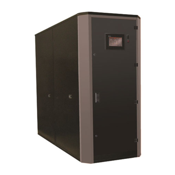
Page 8: Component Description
11. Supply water connection. A 3” diameter Component Description Victaulic grooved connection is provided Touchscreen display. The display on the FF1000. A 3”, 150# class, flange provides easy access for viewing and is provide on the FF1500 – 3000. adjusting boiler operational parameters, 12. -
Page 9: Form: 2435 Revision
Form: 2435 Revision: 9 Free Flex Installation and Operation Manual Date: 9-1-2017 Figure 1: FF1000 External Boiler Connections and Components Figure 2: FF1500 - 3000 External Boiler Connections and Components Bryan Steam LLC, 783 N Chili Ave, Peru IN 46970 Web: www.bryanboilers.com... -
Page 10: Pre-Installation
Form: 2435 Revision: 9 Free Flex Installation and Operation Manual Date: 9-1-2017 B149 Installation Codes. Where required by Pre-Installation the authority having jurisdiction, the installation must conform to the Standard for The customer should examine the equipment Controls and Safety Devices for Automatically for any damage. -
Page 11: Table 2: Clearances And Serviceability
Form: 2435 Revision: 9 Free Flex Installation and Operation Manual Date: 9-1-2017 Description 1000 1500-3000 From Chimney or Vent Collector 18” 18” Flue Gas measured Vent vertically Rear of Boiler - opposite burner 6” 6” Left Side – tube access side on Boiler 16”... -
Page 12: Installation
Form: 2435 Revision: 9 Free Flex Installation and Operation Manual Date: 9-1-2017 3.2.2 Safety Relief Valves Installation Safety relief valve(s) are shipped loose. Receiving The Boiler Connections are provided in the top of the boiler for the safety relief valve(s). The safety The boiler is shipped from the factory with relief valve discharge piping must be the same (4) shipping feet/legs bolted to the skids. -
Page 13: Condensate Drain Connection
3.5. NO VALVE is to be installed in this line from the boiler to point 3.2.6.1 FF1000 Condensate Drain Trap of discharge. Ensure that the condensate drain trap is filled The condensate drain trap should be flushed... -
Page 14: Gas Supply Connection
Form: 2435 Revision: 9 Free Flex Installation and Operation Manual Date: 9-1-2017 After completion of the gas-piping hookup, the installation must be checked for leaks. Leaks shall be checked using a soap and water solution. All joints up to the main motorized gas valve shall be checked. -
Page 15: Combustion Air Openings
Form: 2435 Revision: 9 Free Flex Installation and Operation Manual Date: 9-1-2017 Positive means for supplying an ample One opening starting within 12” of the top of amount of outside air, allowing for the the boiler room and one starting within 12” of complete combustion of the gas, must be the bottom of the boiler room shall be provided. -
Page 16: Louvers, Grilles, And Screens
Form: 2435 Revision: 9 Free Flex Installation and Operation Manual Date: 9-1-2017 If exhaust fans are utilized, additional air shall 3.3.2.3 Motorized Louvers: be provided to replace the exhausted air. Motorized louvers shall be interlocked with Each boiler and other appliance must be the appliance so they are proven in the full interlocked to prevent operation when the open position prior to main burner ignition... -
Page 17: Ducted Combustion Air
Form: 2435 Revision: 9 Free Flex Installation and Operation Manual Date: 9-1-2017 NFPA 54, National Fuel Gas Code (ANSI 2. If this boiler is being installed in Z223.1) Massachusetts, follow the Massachusetts Code Instructions printed later in this ASME CSD-1, Controls and Safety Devices section. - Page 18 Form: 2435 Revision: 9 Free Flex Installation and Operation Manual Date: 9-1-2017 9. The boiler’s venting is Category IV 16. Use appropriately designed thimbles when (positive vent pressure, flue condensing), passing through combustible walls or with regards to the National Fuel Gas roofs.
-
Page 19: Category Ii Venting
Form: 2435 Revision: 9 5. Vertical venting is recommended. Other Free Flex Installation and Operation Manual Date: 9-1-2017 horizontal and vertical arrangements may b. Refer to the appropriate drawings in be acceptable if proven by the vent Appendix D of this manual to manufacturers design calculations. -
Page 20: Massachusetts
Form: 2435 Revision: 9 installed on the next adjacent floor Free Flex Installation and Operation Manual Date: 9-1-2017 level. 3.4.2 Massachusetts b. In the event that the requirements of this subdivision cannot be met at the The commonwealth of Massachusetts requires time of completion of installation, the compliance with regulation 248 CMR 4.00 to owner shall have a period of (30) -
Page 21: Combustion Air And Venting Requirements For Canada
Form: 2435 Revision: 9 Required To Be Vented” in the ii. The “special venting systems” Free Flex Installation and Operation Manual Date: 9-1-2017 most current edition of NFPA 54 shall be Product Approved by the as adopted by the Board; and Board, and the instructions for the ii. -
Page 22: Combustion Air Supply Dampers, Louvers, And Grilles
Form: 2435 Revision: 9 Free Flex Installation and Operation Manual Date: 9-1-2017 Combustion Air: For combustion air where When combustion air is supplied by the air supply is provided by natural airflow mechanical means, an airflow sensing device from outdoors, in addition to the opening for shall be installed and wired into the safety ventilation air, there shall be permanent limit circuit of the primary safety control to... -
Page 23: Requirements
Free Flex Installation and Operation Manual Date: 9-1-2017 any other appliance. This boiler Table 5: Electrical Requirements operates at a positive vent pressure. FF1000 • A factory-built chimney used for venting an appliance shall be certified. Voltage 120/1/60 Requirements FF1500 Voltage 3.5.1 Electrical... -
Page 24: Gas Supply Requirements
Min. Max. Model (SCFH) (nps) (iwc) (iwc) It is advised that the circulating pump for FF1000 1000 each boiler be installed as close to the boiler FF1500 1500 as possible in the line to the return connection FF2000 2000 such that system water is pumped towards the... -
Page 25: Water Flow Rates (Variable Primary Pumping Systems)
High Fire Model Δ P boiler system. Scheduled recording of the Δ T (ft) water meter register will show an indication of FF1000 100F a potential slow system leak in addition to FF1500 100F providing insight into any system problems. FF2000... -
Page 26: Table 10 Water Flow Rates For Primary / Secondary Pumping 20F Δt
Free Flex Installation and Operation Manual Date: 9-1-2017 20 F Δ T Flow Rate High Model Δ P Fire Fire (ft) Δ T Δ T FF1000 12.7 FF1500 FF2000 16.3 FF2500 FF3000 28.7 Table 10 Water Flow Rates for Primary / Secondary Pumping 20F Δ... -
Page 27: Water Flow Rates (Constant Volume Primary Pumping Systems)
Form: 2435 Revision: 9 Free Flex Installation and Operation Manual Date: 9-1-2017 The removal of pipe chips and other debris 3.5.4.3 Water Flow Rates (Constant from the system before opening the isolation Volume Primary Pumping Systems) valves to the boiler and pumps will help to A constant volume primary pumping system protect this equipment from damage by such shall be sized so that the flow rate specified in... -
Page 28: Replacement Boiler Installations
Form: 2435 Revision: 9 Free Flex Installation and Operation Manual Date: 9-1-2017 Fill the system with this solution, venting all Failure to properly clean the system or to air. Then, with the circulating pump running, install mechanical sediment removal bring the system to design or operating equipment can result in tube blockage and temperature. -
Page 29: Boiler Water Treatment
Form: 2435 Revision: 9 Free Flex Installation and Operation Manual Date: 9-1-2017 Remove the boiler tube access panels (see 4. Maintain the highest possible boiler fuel dimensional drawing in the boiler manual). efficiency. Inspect the tube to header joints to be certain 5. -
Page 30: Table 14 Recommended Feed Water Limits
Form: 2435 Revision: 9 Free Flex Installation and Operation Manual Date: 9-1-2017 Magnesium Sulphate WARNING Corrosion (MgSO4) Chemicals used in treating boiler water Silicon Dioxide (SiO2) Hard Scale are toxic and/or harmful. Always use protective clothing and equipment when working with/near chemicals. Contact It should be noted that water boilers may well local authorities to determine if treated need chemical treatment for the first filling... -
Page 31: System Start-Up
Form: 2435 Revision: 9 Free Flex Installation and Operation Manual Date: 9-1-2017 NOTICE SYSTEM START-UP Refer to the Concert Boiler Control WARNING manual for detailed instructions on the use of the hydronic control and display. Completely read, understand and follow all instructions in this manual, Concert Boiler Control manual, and all other component manuals supplied with this... -
Page 32: Boiler Commissioning
Form: 2435 Revision: 9 the boiler jacket conforms to Table 6 for Free Flex Installation and Operation Manual Date: 9-1-2017 maximum and minimum supply pressure. 6. Menu > Operation > Auto / Manual 4. Repeat steps 2 and 3 for boiler gas train Rate Control >... -
Page 33: Figure 6: High Fire Adjustment On The Main Gas Valve Regulator
Form: 2435 Revision: 9 Free Flex Installation and Operation Manual Date: 9-1-2017 20. Menu > Operation > High/Low > High Warning > Back Arrow (76 password required) Improper adjustments to the low fire offset adjustment can lead to rough light- 21. -
Page 34: Finish Commissioning The Boiler
Form: 2435 Revision: 9 Free Flex Installation and Operation Manual Date: 9-1-2017 Finish Commissioning the Boiler: Reconnect any wires from the external control system, if applicable. 1. Perform an operation test of the external control system. 2. Place system control back in normal operation, if necessary. -
Page 35: Testing Of Controls And Safety Devices
Form: 2435 Revision: 9 Free Flex Installation and Operation Manual Date: 9-1-2017 Testing of Controls and Safety Devices Prior to placing the boiler in operation, the installing contractor or other responsible personnel must perform safety and control device limit tests to ensure proper operation of the appliance. Refer to Table 15 for recommended method(s) of carrying out these safety limit devices tests. -
Page 36: Ignition Failure
Form: 2435 Revision: 9 Free Flex Installation and Operation Manual Date: 9-1-2017 4.10 Ignition Failure After the first ignition failure, the boiler goes into a hard lockout and a manual reset of the Concert Boiler Control is required to restart the boiler. The boiler will then attempt to light off after it has completed its post-purge process. -
Page 37: Service, Maintenance, And Inspection
Form: 2435 Revision: 9 Free Flex Installation and Operation Manual Date: 9-1-2017 Read, understand and follow all the instructions and warnings contained in all Service, Maintenance, and Inspection sections this manual. instructions and warnings contained in all General Maintenance: of the component instruction manuals. 1. -
Page 38: Weekly
Form: 2435 Revision: 9 Free Flex Installation and Operation Manual Date: 9-1-2017 2. If inspection of the boiler tube surfaces 2. Make visual check of instrument and reveals a build-up of soot (carbon), the equipment settings against factory tube surfaces should be thoroughly recommended specifications. -
Page 39: Burner Assembly Cleaning
Form: 2435 Revision: 9 Free Flex Installation and Operation Manual Date: 9-1-2017 3. Be careful not to damage or disturb the insulation inside of the heat exchanger. Figure 7: Ignition Assembly 1. Igniter 2. Ultra-Violet (UV) Scanner • 3. ½” Heat Insulator •... -
Page 40: Tube Replacement Procedure
Form: 2435 Revision: 9 Free Flex Installation and Operation Manual Date: 9-1-2017 Tube Replacement Procedure NOTICE Performing a regular boiler inspection will prolong the life of the heat exchanger, and ensure optimal function and energy efficiency. For best practices, adhere to the general guidelines outlined in the service and maintenance section of this manual. -
Page 41: Figure 8: Panel Removal In Preparation For Tube Inspection
Form: 2435 Revision: 9 Free Flex Installation and Operation Manual Date: 9-1-2017 Figure 8: Panel Removal in Preparation for Tube Inspection Bryan Steam LLC, 783 N Chili Ave, Peru IN 46970 Web: www.bryanboilers.com Phone: 765-473-6651 Fax: 765-473-3074 Email: sales@bryansteam.com... -
Page 42: Figure 9: Tube Puller Insertion
Form: 2435 Revision: 9 1. Loosen tube-ends. Insert tube puller between the tube-end and header. Apply pressure to the Free Flex Installation and Operation Manual Date: 9-1-2017 puller and strike the side of the tube two or three times with a hammer to help loosen the tube- end in the upper and lower header. -
Page 43: Form
Form: 2435 Revision: 9 6. Insert both ends of the tubes into the headers. Insert the lower tube-end into the bottom Free Flex Installation and Operation Manual Date: 9-1-2017 header first. Then insert the top tube-end into the top header. Insert all replacement tubes before driving them. -
Page 44: Safety And Operating Controls
Form: 2435 Revision: 9 Free Flex Installation and Operation Manual Date: 9-1-2017 Safety and Operating Controls All of the safety control devices listed in Table 16 are logically linked to the Concert Boiler Control that supervises the sequence of operation of the boiler for safe and efficient operation. It does so by ensuring proper light off and firing of the main burner and if need be, will immediately cut-off gas supply to the main burner when gas pressure, water temperature, water flow or another critical attribute is outside of the operational settings. -
Page 45: Troubleshooting
Form: 2435 Revision: 9 Free Flex Installation and Operation Manual Date: 9-1-2017 Troubleshooting Refer to the troubleshooting section in the Concert Boiler Control manual on how to navigate the Limit String Status screen that shows an active safety limit status and for an in-depth guide to all the possible lockouts as well as recommended corrective actions for restore boiler operation. - Page 46 Form: 2435 Revision: 9 Table 17: General Troubleshooting Free Flex Installation and Operation Manual Date: 9-1-2017 CORRECTIVE ACTION INDICATION POSSIBLE CAUSE Check loose 120 Vac connection wiring between boiler J-Box and transformer or 24 Vdc power supply. Check for loose 24 Vac connection wiring No 120 Vac Power at Display Completely between transformer and Control.
- Page 47 Form: 2435 Revision: 9 Table 17: General Troubleshooting Free Flex Installation and Operation Manual Date: 9-1-2017 CORRECTIVE ACTION INDICATION POSSIBLE CAUSE Remove the boiler’s side panels and check for flue gas leakage around the heat exchanger, Leakage burner mounting plate, and blower transition piece.
-
Page 48: Appendix A Sizing Gas Piping
Form: 2435 Revision: 9 Free Flex Installation and Operation Manual Date: 9-1-2017 Appendix A Sizing Gas Piping Design the gas piping system to provide an adequate gas supply to the boiler. Refer to Table 6 for minimum and maximum gas supply pressures and boiler capacities. Also consider existing and expected future gas utilizing equipment (i.e., water heater, cooling equipment). -
Page 49: Table 19: Equivalent Lengths Of Standard Pipe Fittings And Valves
Form: 2435 Revision: 9 Free Flex Installation and Operation Manual Date: 9-1-2017 Table 19: Equivalent Lengths Of Standard Pipe Fittings And Valves Valves Fully Open (Screwed, Flanged, Schedule 40, Screwed Fittings Welded) 90 deg. Pipe Tee, Flow Size 90 deg. 45 deg. -
Page 50: Appendix B Vent And Combustion Air Pressure Drop Data
FF3000 Pressure Drop in Equivalent Feet (Flue Vent) 2.22 11.11 2591 7.14 3.57 1650 .267 1.35 1152 FF1000 Pressure Drop in Equivalent Feet (Combustion Air Duct) Air Duct Straight Length 90° Elbow 45° Elbow Velocity Diameter (in.) (eq ft/ft) (eq ft) (eq ft) (fpm) 6.25... -
Page 51: Appendix C Installation & Startup Report
Form: 2435 Revision: 9 Free Flex Installation and Operation Manual Date: 9-1-2017 Appendix C Installation & Startup Report Bryan Steam LLC, 783 N Chili Ave, Peru IN 46970 Web: www.bryanboilers.com Phone: 765-473-6651 Fax: 765-473-3074 Email: sales@bryansteam.com... -
Page 52: Appendix D Venting Diagrams
Form: 2435 Revision: 9 Free Flex Installation and Operation Manual Date: 9-1-2017 Appendix D Venting Diagrams Appendix D.1 Typical Horizontal Vent Piping Bryan Steam LLC, 783 N Chili Ave, Peru IN 46970 Web: www.bryanboilers.com Phone: 765-473-6651 Fax: 765-473-3074 Email: sales@bryansteam.com... -
Page 53: Appendix D.2 Typical Vertical Pressurized Venting
Form: 2435 Revision: 9 Free Flex Installation and Operation Manual Date: 9-1-2017 Appendix D.2 Typical Vertical Pressurized Venting Bryan Steam LLC, 783 N Chili Ave, Peru IN 46970 Web: www.bryanboilers.com Phone: 765-473-6651 Fax: 765-473-3074 Email: sales@bryansteam.com... -
Page 54: Appendix E Combustion Air Diagrams
Form: 2435 Revision: 9 Free Flex Installation and Operation Manual Date: 9-1-2017 Appendix E Combustion Air Diagrams Appendix E.1 Typical Horizontal Air Intake Piping Bryan Steam LLC, 783 N Chili Ave, Peru IN 46970 Web: www.bryanboilers.com Phone: 765-473-6651 Fax: 765-473-3074 Email: sales@bryansteam.com... -
Page 55: Appendix E.2 Typical Vertical Air Intake Piping
Form: 2435 Revision: 9 Free Flex Installation and Operation Manual Date: 9-1-2017 Appendix E.2 Typical Vertical Air Intake Piping Bryan Steam LLC, 783 N Chili Ave, Peru IN 46970 Web: www.bryanboilers.com Phone: 765-473-6651 Fax: 765-473-3074 Email: sales@bryansteam.com... -
Page 56: Appendix F Boiler Piping Diagrams
Form: 2435 Revision: 9 Free Flex Installation and Operation Manual Date: 9-1-2017 Appendix F Boiler Piping Diagrams Appendix F.1 Single Boiler, Primary / Secondary Bryan Steam LLC, 783 N Chili Ave, Peru IN 46970 Web: www.bryanboilers.com Phone: 765-473-6651 Fax: 765-473-3074 Email: sales@bryansteam.com... -
Page 57: Appendix F.2 Multiple Boilers, Primary Reverse-Return Piping
Form: 2435 Revision: 9 Free Flex Installation and Operation Manual Date: 9-1-2017 Appendix F.2 Multiple Boilers, Primary Reverse-Return Piping Bryan Steam LLC, 783 N Chili Ave, Peru IN 46970 Web: www.bryanboilers.com Phone: 765-473-6651 Fax: 765-473-3074 Email: sales@bryansteam.com... -
Page 58: Appendix F.3 Multiple Boilers, Primary / Secondary Reverse Return Piping
Form: 2435 Revision: 9 Free Flex Installation and Operation Manual Date: 9-1-2017 Appendix F.3 Multiple Boilers, Primary / Secondary Reverse Return Piping Bryan Steam LLC, 783 N Chili Ave, Peru IN 46970 Web: www.bryanboilers.com Phone: 765-473-6651 Fax: 765-473-3074 Email: sales@bryansteam.com... -
Page 59: Appendix F.4 Multiple Boilers, Primary / Secondary Piping
Form: 2435 Revision: 9 Free Flex Installation and Operation Manual Date: 9-1-2017 Appendix F.4 Multiple Boilers, Primary / Secondary Piping Bryan Steam LLC, 783 N Chili Ave, Peru IN 46970 Web: www.bryanboilers.com Phone: 765-473-6651 Fax: 765-473-3074 Email: sales@bryansteam.com... -
Page 60: Appendix F.5 Multiple Boilers, Primary / Secondary Piping, Heating With Domestic Hot Water
Form: 2435 Revision: 9 Free Flex Installation and Operation Manual Date: 9-1-2017 Appendix F.5 Multiple Boilers, Primary / Secondary Piping, Heating with Domestic Hot Water Bryan Steam LLC, 783 N Chili Ave, Peru IN 46970 Web: www.bryanboilers.com Phone: 765-473-6651 Fax: 765-473-3074 Email: sales@bryansteam.com... -
Page 61: Appendix F.6 Multiple Boilers, Primary / Secondary Piping, Heating With Domestic Hot Water (Continued)
Form: 2435 Revision: 9 Free Flex Installation and Operation Manual Date: 9-1-2017 Appendix F.6 Multiple Boilers, Primary / Secondary Piping, Heating with Domestic Hot Water (continued) Bryan Steam LLC, 783 N Chili Ave, Peru IN 46970 Web: www.bryanboilers.com Phone: 765-473-6651 Fax: 765-473-3074 Email: sales@bryansteam.com... -
Page 62: Appendix G Water Flow Pressure Drops
Form: 2435 Revision: 9 Free Flex Installation and Operation Manual Date: 9-1-2017 Appendix G Water Flow Pressure Drops FREE FLEX 1500 FREE FLEX 2000 FREE FLEX 1000 Delta T Delta T Delta T Ft. Hd. Ft. Hd. Ft. Hd. 100F 0.51 100F 0.37... -
Page 63: Appendix H Wiring Diagrams
Form: 2435 Revision: 9 Free Flex Installation and Operation Manual Date: 9-1-2017 Appendix H Wiring Diagrams Appendix H.1 FF1000 Wiring Diagram Bryan Steam LLC, 783 N Chili Ave, Peru IN 46970 Web: www.bryanboilers.com Phone: 765-473-6651 Fax: 765-473-3074 Email: sales@bryansteam.com... - Page 64 Form: 2435 Revision: 9 Free Flex Installation and Operation Manual Date: 9-1-2017 Wiring diagrams are for reference only, please refer to the wiring shipped with the boiler for accuracy. Bryan Steam LLC, 783 N Chili Ave, Peru IN 46970 Web: www.bryanboilers.com Phone: 765-473-6651 Fax: 765-473-3074 Email: sales@bryansteam.com...
-
Page 65: Appendix H.2 Ff1500 To Ff3000 115 Vac Single Phase Wiring Diagram
Form: 2435 Revision: 9 Free Flex Installation and Operation Manual Date: 9-1-2017 Appendix H.2 FF1500 To FF3000 115 VAC Single Phase Wiring Diagram Bryan Steam LLC, 783 N Chili Ave, Peru IN 46970 Web: www.bryanboilers.com Phone: 765-473-6651 Fax: 765-473-3074 Email: sales@bryansteam.com... -
Page 66: Appendix H.3 Ff1500 To Ff3000 208 - 230 Vac Single Phase Wiring Diagram
Form: 2435 Revision: 9 Free Flex Installation and Operation Manual Date: 9-1-2017 Appendix H.3 FF1500 To FF3000 208 – 230 VAC Single Phase Wiring Diagram Bryan Steam LLC, 783 N Chili Ave, Peru IN 46970 Web: www.bryanboilers.com Phone: 765-473-6651 Fax: 765-473-3074 Email: sales@bryansteam.com... - Page 67 Form: 2435 Revision: 9 Free Flex Installation and Operation Manual Date: 9-1-2017 Wiring diagrams are for reference only, please refer to the wiring shipped with the boiler for accuracy. Bryan Steam LLC, 783 N Chili Ave, Peru IN 46970 Web: www.bryanboilers.com Phone: 765-473-6651 Fax: 765-473-3074 Email: sales@bryansteam.com...
-
Page 68: Appendix H.4 Ff2000 To Ff3000 208-460 Vac Three Phase Wiring Diagram
Form: 2435 Revision: 9 Free Flex Installation and Operation Manual Date: 9-1-2017 Appendix H.4 FF2000 To FF3000 208-460 VAC Three Phase Wiring Diagram Bryan Steam LLC, 783 N Chili Ave, Peru IN 46970 Web: www.bryanboilers.com Phone: 765-473-6651 Fax: 765-473-3074 Email: sales@bryansteam.com... - Page 69 Form: 2435 Revision: 9 Free Flex Installation and Operation Manual Date: 9-1-2017 Wiring diagrams are for reference only, please refer to the wiring shipped with the boiler for accuracy. Bryan Steam LLC, 783 N Chili Ave, Peru IN 46970 Web: www.bryanboilers.com Phone: 765-473-6651 Fax: 765-473-3074 Email: sales@bryansteam.com...
-
Page 70: Appendix I Repair Parts
Should you require assistance in locating a Bryan Steam representative in your area, or have questions regarding the availability of Bryan Steam products or repair parts, please contact Bryan Steam Customer Service at (717)-239-7642 or Fax (877)-501-5212. Appendix I.1 FF1000 Heat Exchanger Bryan Steam LLC, 783 N Chili Ave, Peru IN 46970 Web: www.bryanboilers.com Phone: 765-473-6651 Fax: 765-473-3074 Email: sales@bryansteam.com... -
Page 71: Table 21: Heat Exchanger Parts
Form: 2435 Revision: 9 Free Flex Installation and Operation Manual Date: 9-1-2017 Table 21: Heat Exchanger Parts Item Numbe Description Quantity Part Number Lower Header 105670-01 Upper Header 105669-01 Convection Tubes Long Return (Yellow Paint) 105696-01 Convection Tubes Short Return (Black Paint) 105696-04 Furnace Tubes Long Return 105696-02... -
Page 72: Appendix I.2 Ff1000 Burner Assembly
Form: 2435 Revision: 9 Free Flex Installation and Operation Manual Date: 9-1-2017 Appendix I.2 FF1000 Burner Assembly Table 22: Burner Assembly Item Quantity Part Number Description Number 106684-01 Ultra-Violet (UV) Scanner 8026217 Heat Insulator 107031-01 Ultra-Violet (UV) Lens Gasket 106685-01... -
Page 73: Appendix I.3 Gas Train And Upper Vestibule Controls
Form: 2435 Revision: 9 Free Flex Installation and Operation Manual Date: 9-1-2017 Appendix I.3 Gas Train and Upper Vestibule Controls Bryan Steam LLC, 783 N Chili Ave, Peru IN 46970 Web: www.bryanboilers.com Phone: 765-473-6651 Fax: 765-473-3074 Email: sales@bryansteam.com... -
Page 74: Table 23: Gas Train And Upper Vestibule Controls
Form: 2435 Revision: 9 Free Flex Installation and Operation Manual Date: 9-1-2017 Table 23: Gas Train and Upper Vestibule Controls (Quantity) Part Description Number (1) 105326-01 Blower (1) 105327-01 Swirl Plate (1) 105325-01 Manual Shut-Off Ball Valve (1) 105330-01 Main Gas Valve (1) 105328-01 High Gas Pressure Switch (1) 105329-01... -
Page 75: Appendix I.4 Jacket
Form: 2435 Revision: 9 Free Flex Installation and Operation Manual Date: 9-1-2017 Appendix I.4 Jacket Bryan Steam LLC, 783 N Chili Ave, Peru IN 46970 Web: www.bryanboilers.com Phone: 765-473-6651 Fax: 765-473-3074 Email: sales@bryansteam.com... -
Page 76: Table 24: Jacket
Form: 2435 Revision: 9 Free Flex Installation and Operation Manual Date: 9-1-2017 Table 24: Jacket (Quantity) Part Description Number Base (1) 105124-01 Front Left (1) 105172-01 Corner Front Right (1) 105172-04 Corner Center Rail (1) 105176-01 Hinges (2) 105714-01 Front Lower (1) 105177-01 Panel Front Door... -
Page 77: Appendix I.5 Outlet Manifold
Form: 2435 Revision: 9 Free Flex Installation and Operation Manual Date: 9-1-2017 Appendix I.5 Outlet Manifold Bryan Steam LLC, 783 N Chili Ave, Peru IN 46970 Web: www.bryanboilers.com Phone: 765-473-6651 Fax: 765-473-3074 Email: sales@bryansteam.com... -
Page 78: Table 25: Outlet Manifold
Form: 2435 Revision: 9 Free Flex Installation and Operation Manual Date: 9-1-2017 Table 25: Outlet Manifold (Quantity) Part Number 30 PSI 50 PSI 60 PSI 75 PSI 100 PSI 125 PSI 150 PSI Description Setting Setting Setting Setting Setting Setting Setting Upper Water (1) 105381-01... -
Page 79: Appendix I.6 Miscellaneous External Components
Form: 2435 Revision: 9 Free Flex Installation and Operation Manual Date: 9-1-2017 Appendix I.6 Miscellaneous External Components Bryan Steam LLC, 783 N Chili Ave, Peru IN 46970 Web: www.bryanboilers.com Phone: 765-473-6651 Fax: 765-473-3074 Email: sales@bryansteam.com... -
Page 80: Table 26: Miscellaneous External Components
Form: 2435 Revision: 9 Free Flex Installation and Operation Manual Date: 9-1-2017 Table 26: Miscellaneous External Components Description (Quantity) Part Number Lower Rear Manifold (1) 105384-01 Water Inlet Manifold (1) 105383-01 Exhaust Stack (1) 105697-01 Condensate Trap (1) 105432-01 3" Victaulic Coupling (3) 104035-02 3"... -
Page 81: Appendix I.7 Controls
Form: 2435 Revision: 9 Free Flex Installation and Operation Manual Date: 9-1-2017 Appendix I.7 Controls Bryan Steam LLC, 783 N Chili Ave, Peru IN 46970 Web: www.bryanboilers.com Phone: 765-473-6651 Fax: 765-473-3074 Email: sales@bryansteam.com... -
Page 82: Free Flex Installation And Operation Manual
Form: 2435 Revision: 9 Free Flex Installation and Operation Manual Date: 9-1-2017 Table 27: Controls (Quantity) Part Number Key No. Description Control Panel (1) 105171-01 Concert Boiler Control (1) 105681-01 24VDC Transformer (1) 105680-01 120/24V Step-down Transformer (1) 801600502 Low Water Cut-Off Reset Box (1) 80160591 Display (1) 105682-01... - Page 83 Form: 2435 Revision: 9 Free Flex Installation and Operation Manual Date: 9-1-2017 Bryan Steam (“seller”) LIMITED WARRANTY Subject to the terms and conditions herein, Seller warrants to the original owner at the original installation site that the pressure vessel and flue LIFETIME THERMAL SHOCK WARRANTY collector are covered against failure due to fireside flue Subject to the terms and conditions herein, Seller...
-
Page 84: Free Flex Installation And Operation Manual Date: 9-1-2017
Form: 2435 Revision: 9 Free Flex Installation and Operation Manual Date: 9-1-2017 claimed defects. Transportation to a factory or Defective installations in general and other designated facility for repairs of any products specifically, any installation, which is made: or items alleged defective shall, in all events, be the In violation of applicable state or responsibility and at the cost of the owner. - Page 85 Form: 2435 Revision: 9 Free Flex Installation and Operation Manual Date: 9-1-2017 conform and be limited to one year from the date of shipment. Severability To the extent that any provisions shall of this warranty would be void or prohibited under applicable law, such provisions shall be limited in effect to the minimum extent necessary to render the remaining provisions hereof enforceable.
Need help?
Do you have a question about the FF1000 and is the answer not in the manual?
Questions and answers