
Related Manuals for Bryan Boilers D Series


Summary of Contents for Bryan Boilers D Series
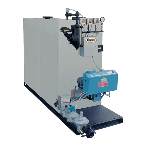
- Page 1 Installation Operation Service Manual Atmospheric Water Boilers BRYAN BOILERS 783 N. CHILI AVENUE, PERU, INDIANA 46970 Telephone: 765-473-6651 / Fax: 765-473-3074 E-Mail: bryanboilers@iquest.net / Internet: www.bryanboilers.com...
-
Page 2: Boiler Foundation
INSTALLATION INSTRUCTIONS ATMOSPHERIC WATER BOILERS NOTE: • Please read all of instruction manual before attempting installation. • Insurance and local or state regulatory codes may contain additional or more stringent requirements than those contained in this manual. Installation must conform to these codes and any other authority having jurisdiction. -
Page 3: Minimum Clearances
MINIMUM CLEARANCES NOTE: These boilers are intended to be installed in a room which is large compared to the size of the boiler. They are not intended for alcove installation and are suitable for installation on non-combustible flooring only. D-SERIES F-SERIES CL-SERIES K-SERIES... -
Page 4: Boiler Connections
1.4 BOILER CONNECTIONS 1.4.1 GENERAL Do not run any pipes along the access panel side of 1.4.4 EXPANSION TANK CONNECTION the boiler. Maintain clearances as shown on the A connection is provided in the top of the boiler for dimensional drawing for servicing of the boiler tubes. connecting piping to the expansion tank. -
Page 5: Electrical Connection
1.5.3 VENTING OF GAS TRAIN COMPONENTS Normally open vent valves - These valves must Gas pressure regulator - The regulator must be be piped to outdoors using pipe no smaller than vented to the outside air, using minimum 1/4" that of the valve. tubing or pipe. - Page 6 damper. Combustion air openings for boilers which inch per 2,000 Btu of total input for all equipment in are equipped with forced draft burners may be the room. NOTE: No rectangular duct may have a reduced to 70% of that required for atmospheric gas dimension of less than 4 inches.
-
Page 7: Manual References
ESTIMATING FLUE GAS FLOW RATE (ACFM) stack diameter used. The result is the Stack Exit Flue gas volumetric flow rate in SCFM (standard cubic Velocity in feet per second. feet per minute) and ACFM (actual cubic feet per ESTIMATING STACK EMISSIONS minute) can be estimated by using the information in Table 1.8.1C lists approximate emissions of NOx 1.8.1A. - Page 8 TABLE 1.8.1B: STACK EXIT VELOCITY Estimated STACK EXIT VELOCITY Calculation (Multiply total ACFM times the velocity factor below velocity in feet per second) STACK INSIDE VELOCITY STACK INSIDE VELOCITY STACK INSIDE VELOCITY DIAMETER (Inches) FACTOR DIAMETER (Inches) FACTOR DIAMETER (Inches) FACTOR 0.0849 0.00943...
- Page 9 1.8.4 BOILER ROOM PRESSURIZATION The boiler room must be supplied with adequate air diverters) as outlined in "Combustion Air Supply", for combustion and for proper operation of draft Section this manual. control devices (barometric dampers or draft WARNING THE BOILER ROOM MUST BE MAINTAINED AT A IT ALSO MAY BE ADVISABLE TO INSTALL AN POSITIVE OR NEUTRAL PRESSURE (RELATIVE AUTOMATIC VENT DAMPER IN THE VENT...
-
Page 10: Installation
INSTALL BAROMETRIC DRAFT taking a CO reading and a CO reading at the boiler CONTROL IN A ROOM SEPARATE FROM THE flue. Reference Table 2.5A for appropriate values. BOILER. COMBUSTION READINGS AND DRAFT SETTINGS MUST BE DONE BY A QUALIFIED BOILER SERVICE The stop and two cover plates are painted in a different TECHNICIAN. - Page 11 Fig. 1.8.6C: BAROMETRIC CONTROL WITH BAFFLE FOR CONTROL OF EXCESSIVE DRAFT FIG. 1.8.6D: SUGGESTED BAFFLE DIMENSIONS 1.8.7 ACCEPTABLE VENT TYPES TYPE B GAS VENTS manufacturer's instructions and with adherence to Type B gas vents may be used with listed water the codes and clearances as outlined herein.
- Page 12 WARNING UNDER NO CIRCUMSTANCES SHOULD THE FLUE PIPE BE CONNECTED TO THE CHIMNEY OF AN OPEN FIREPLACE TABLE 1.8.7A TABLE 1.8.7B WATER BOILER & STEAM BOILERS TO 50 PSIG (STEAM BOILERS OVER 50 PSIG) Diameter of Minimum Thickness, Diameter of Minimum Thickness, Connector, Inches Inch (Gauge)
- Page 13 pipe used as a vent connector must not pass vent damper (when properly installed and through any floor or ceiling. interlocked with the boiler gas controls). CHIMNEY CONNECTION USE OF THIMBLES In entering a passageway in a masonry or metal Vent connectors made of single wall metal pipe chimney, the vent connector must be installed must not pass though any combustible wall...
-
Page 14: Marking Of Gas Vents
MINIMUM REQUIRED DISTANCE FROM COMBUSTIBLE MATERIAL EQUIPMENT TYPE Listed Type B Vent Single Wall Metal Factor Built Chimney Pipe UL Listed F-Series Water or 15 psig 6" as listed Steam with Draft Diverter as listed UL Listed CL-Series Water or 15 psig 6"... - Page 15 This label must be attached to the wall or ceiling The authority having jurisdiction must determine at a point near where the gas vent connector whether their area constitutes such a locality. enters the wall, ceiling or chimney. 1.8.11 VENTING MULTIPLE APPLIANCES ON A COMMON VENT COMMON GAS VENT PRESSURIZED VENTS...
- Page 16 VENTILATING HOODS EXHAUST Listed vent caps or roof assemblies must have a SYSTEMS rated venting capacity no less than the vent. Ventilating hoods or exhaust systems may be used to vent atmospheric gas appliances. When Single wall vents must terminate in an approved these are used, however, such mechanical cap which does not obstruct the exit.
-
Page 17: Multiple Appliance Installations
on the Equipment List/Submittal Data in the boiler INDUCED DRAFT FANS manual. The boilers will also be provided with a Occasionally, the characteristics of an installation label indicating that they have been prepared for are such that a natural draft vent system will not high altitude. - Page 18 1.8.15 QUICK SELECTION FOR VENT SIZING CHARTS GENERAL RECTANGULAR VENTS These charts were generated using Vent systems may be rectangular as well as procedure described in Chapter 26 of the circular. Table 1.8.15F has been provided to give ASHRAE Equipment Handbook (1979). The the circular equivalent of a rectangular duct.
- Page 19 Table 1.8.15B ALTITUDE CORRECTION FACTOR, F (Multiple factor times sea level Input, MBH) Altitude (ft) Factor, F Altitude (ft) Factor, F 0 to 1999 1.00 2000 1.075 6000 1.247 2500 1.096 6500 1.272 3000 1.116 7000 1.296 3500 1.136 7500 1.322 4000 1.157...
- Page 20 STEP 5: CORRECT EQUIVALENT INPUT FOR calculated in Step 4. This factor is designated as SYSTEM K-FACTOR The capacities listed in Table 1.8.15C are based Multiply the equivalent input calculated in Step 2 on a system k-factor equal to 7.5. For any other times factor F from Table 1.8.15E.
- Page 21 Stack Table 1.8.15C: Approximate Stack Capacities (MBH) Diam. (Based on Atmospheric Boiler with Draft Hood) (in.) 1140 1020 1140 1250 1450 1060 1130 1200 1260 1410 1550 1790 1000 1080 1150 1220 1290 1410 1520 1630 1730 1820 2040 2330 2580 1110 1240...
-
Page 23: Special Applications
Table 1.8.15F: CIRCULAR EQUIVALENTS OF RECTANGULAR BREECHINGS & STACKS WIDTH HEIGHT (INCHES) (INCHES) 1.8.16 SPECIAL APPLICATIONS FLUE GAS ECONOMIZERS HIGH EFFICIENCY APPLIANCES When applying flue gas economizers, care must be taken High efficiency appliances require special consideration in to assure that: vent design because of the reduced stack gas 1. - Page 24 1.9 BURNERS AND GAS TRAINS - ATMOSPHERIC BOILERS 1.9.1 GAS BURNER ASSEMBLY nameplate. Table 1.9A has average manifold The gas burner in theses boilers is an assembly readings for the atmospheric boilers. A tapping is of burner tubes, along with the necessary fittings, supplied on the manifold for this purpose.
- Page 25 PILOT GAS PRESSURE REGULATOR allow gas flow only if the ignition source for the The pilot gas valves are electrically operated by main flame is a proven pilot. the boiler flame supervisory and operating controls. Read carefully the enclosed instruction sheet on the automatic gas valves as well as PILOTSTATS Lighting Instructions.
-
Page 26: Test Of Gas Piping
filling the unit with water. The pressure should be can develop from shipping vibration or from gradually increased to a pressure just below the installation procedures. It is often necessary to setting of boiler safety relief valve(s). retighten such fittings after installation and after the boiler has been operated for some time. - Page 27 START-UP AND OPERATION WATER BOILERS WARNING: IMPROPER SERVICING AND START-UP OF THIS EQUIPMENT MAY CREATE A POTENTIAL HAZARD TO EQUIPMENT AND TO OPERATORS OR PERSONS IN THE BUILDING. SERVICING AND START-UP MUST BE DONE ONLY BY FULLY TRAINED AND QUALIFIED PERSONNEL. CAUTION: BEFORE DISCONNECTING OR OPENING ANY FUEL LINE, OR BEFORE CLEANING OR REPLACING PARTS OF ANY KIND TAKE THE FOLLOWING PRECAUTIONS:...
-
Page 28: Checking Burner Input
NOTE 2.1.6 MINIMUM INPUT ADJUSTMENT - DUAL DIAPHRAGM GAS VALVE HIGH/LOW BY-PASS FIRE ADJUSTMENT SHOULD SYSTEM RESULT IN A GAS PRESSURE ON THE The minimum input on this control system is NOT BURNER MANIFOLD EQUAL TO 1" WATER adjustable. The maximum input must be properly COLUMN FOR NATURAL GAS AND 3"... - Page 29 2.3 SAFETY SHUT-OFF DEVICES (FLAME SUPERVISION) 2.3.1 FLAME SUPERVISORY SYSTEM flame loss. In addition to the information given in The boiler is equipped with a flame supervisory Lighting Instructions, operating sequence and system, either the Thermocouple type (such as a troubleshooting information may be found in the combination gas valve or a pilotstat) or electronic manufacturer's instructions in the Boiler manual.
- Page 30 sensing level. The low water cut-off controls must point. This type of control must be operationally be operationally tested by manually lowering the tested as described in Section 2.4.1 and also to boiler water level (by opening the drain valve). assure that the make-up water is introduced as The boiler should cycle off when the water level needed.
- Page 31 FORCED DRAFT OIL FIRED BOILERS BOILER SERIES DRAFT AT SMOKE BOILER HIGH FIRE HIGH FIRE (ppm) OUTLET (i.w.c.) -0.01 TO -0.04 10.0 TO 12.0 % 4.0 TO 7.2 % < 400 0.0 TO -0.04 10.0 TO 12.0 % 4.0 TO 7.2 % <...
-
Page 32: Maintenance Schedule
2.6 OPERATING INSTRUCTIONS 2.6.1 FAMILIARIZATION WITH MANUAL(S) The operating instructions should be kept in the The user of the boiler must familiarize himself pocket in the boiler for F Series boilers or with this manual (and the burner manual for those adjacent to the boiler for all others. -
Page 33: Cleaning The Boiler And System - New Systems
CARE AND MAINTENANCE WATER BOILERS CAUTION: • The boiler area should be kept free of combustible materials, gasoline and other flammable liquids. • The boiler and venting system must be kept free of obstructions of the air louvers and draft hood relief openings. -
Page 34: Boiler Water Treatment
3.2 REPLACEMENT BOILER INSTALLATIONS: PROTECTION AGAINST CORROSION & SEDIMENT CLEAN OR REPLACE ALL SYSTEM PIPING A booster pump may be required to overcome the AND HEATING UNITS additional pressure drop introduced in the line by Arrange for chemical or mechanical cleaning of the filter. -
Page 35: External "Fire-Side" Cleaning
Dissolved oxygen will cause severe boiler tube DRAINING AND REFILLING THE BOILER & corrosion. SYSTEM If the system is drained and then refilled, chemical treatment is essential to treat the raw water. Use only clean, softened water. 3.4 EXTERNAL "FIRE-SIDE" CLEANING PURPOSE a protective cover during cleaning to prevent soot Carbon (soot) is an insulator and is corrosive. - Page 36 4. Confirm boiler area is free of combustible 2. Check operating control, high limit, low fire start materials and that there is nothing obstructing air control, and low water cutoff as specified in openings, draft hood relief openings, etc. manufacturer's instructions. 5.
Need help?
Do you have a question about the D Series and is the answer not in the manual?
Questions and answers