Table of Contents
Advertisement
Quick Links
Free Flex I&O manual
P/N 105641-03
For service and repair to the boiler, call your heating contractor. When seeking information on the boiler from
the manufacturer, provide boiler model and serial number as shown on the rating label.
Boiler Model:
Installation Date:
Heating Contractor:
Address:
!
WA R NING
This manual must only be used by a qualified heating installer/service
technician. Read all instructions in this manual before installing. Perform
steps in the order given. Failure to comply could result in severe
personal injury, death, or substantial property damage.
Bryan Steam, LLC
Phone: 765-473-6651
FREE FLEX
High Efficiency, Low Emission
CONDENSING BOILER
INSTALLATION & OPERATION MANUAL
A
S
M
E
H
783 N Chili Ave, Peru, IN 46970
Serial Number:
Type System:
Phone/Email:
Revision: 13
Date: 06/24/2022
www.bryanboilers.com
sales@bryansteam.com
Advertisement
Table of Contents
Troubleshooting

Related Manuals for Bryan Boilers FREE FLEX


Summary of Contents for Bryan Boilers FREE FLEX
- Page 1 Free Flex I&O manual Revision: 13 P/N 105641-03 Date: 06/24/2022 FREE FLEX High Efficiency, Low Emission CONDENSING BOILER INSTALLATION & OPERATION MANUAL For service and repair to the boiler, call your heating contractor. When seeking information on the boiler from the manufacturer, provide boiler model and serial number as shown on the rating label.
-
Page 2: Table Of Contents
Disclaimers and Local Codes Commissioning Free Flex 1000 - Free Flex 3000 Test and Inspections Component Description Dual Fuel Free Flex 1500 - Free Flex 6000 - Touchscreen display. Switching Fuels II. Pre-Installation Commissioning Free Flex 1500 - Free Flex 6000... - Page 3 Figure 17: Panel Removal in Preparation for Tube Inspection - Free Flex 1000 Figure 18: Panel Removal in Preparation for Tube Inspection - Free Flex 1500 - Free Flex 3000 Figure 19: Panel Removal in Preparation for Tube Inspection - Free Flex 3000 - Free Flex 6000 Figure 20: Tube Puller Insertion...
- Page 4 Figure 31: Free Flex 1500 To Free Flex 3000 115 VAC Single Phase Wiring Diagram Figure 32: Free Flex 1500 To Free Flex 3000 208 – 230 VAC Single Phase Wiring Diagram Figure 33: Free Flex 2000 To Free Flex 3000 208-460 VAC Three Phase Wiring Diagram Figure 34: Free Flex 1500 To Free Flex 3000 High Turndown...
- Page 5 Fittings And Valves Table 34: Specific Gravity Correction Factors Table 9: Approved Vent Manufacturers and Appendix B: Air Switch Adjustment Materials Free Flex 1500 - 6000 Table 10: Stainless Steel and CPVC Vent Adapters 21 Appendix C: Venting Diagrams Table 11: Polypropylene Vent Adapters Appendix D: Combustion Air Diagrams Table 12: Stainless Steel Vent and Intake...
-
Page 6: Introduction
I. Introduction B. Disclaimers and Local Codes A. Important Information Installation must conform to the requirements of The following terms are used throughout this the authority having jurisdiction. In the absence of manual to bring attention to the presence of hazards such requirements, installation must conform to the of various risk levels, or to important information National Fuel Gas Code, NFPA 54/ANSI Z223.1, and/... -
Page 7: Test And Inspections
Free Flex 1000. A 3”, 150# class, flange 1. Boiler On/Off switch. is provide on the Free Flex 1500 – 3000. A 6”, 150# class, flange is provided on the Free Flex 3500-6000. Bryan Steam, LLC www.bryanboilers.com... -
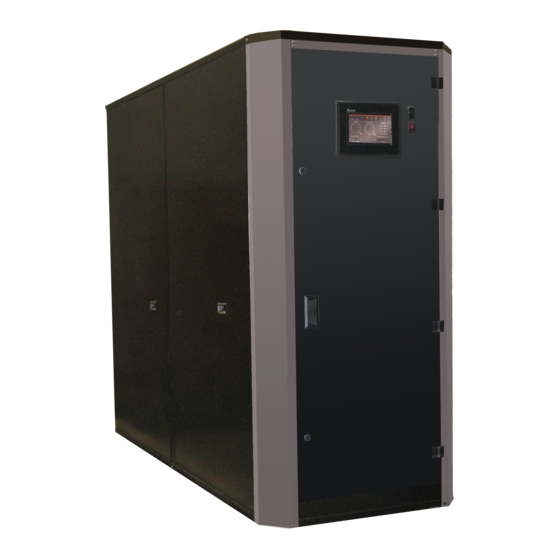
Page 8: Figure 1: Free Flex 1000 External Boiler Connections
12. Boiler reset push button 13. Boiler water temperature gauge. 14. Boiler water pressure gauge. References 16 to 18 are only used on Free Flex 3500 – Free Flex 6000 15. Boiler Hand/Off/Auto 16. Push Button Display. The display provides... -
Page 9: Pre-Installation
II. Pre-Installation B. Boiler Foundation The customer should examine the equipment for any damage. It is the responsibility of the installer Before uncrating, the boiler location should be to ensure all parts supplied with the equipment are prepared. The boiler should set upon a good level fitted in a correct and safe manner. -
Page 10: Figure 4: Clearances And Serviceability
16” 23” 23” struction Right Side – tube access side on standard construction 6” 6” 23” (Free Flex 3500-6000) Free Flex 1500 - 3000 only 23” Bryan Steam, LLC www.bryanboilers.com Phone: 765-473-6651 783 N Chili Ave, Peru, IN 46970 sales@bryansteam.com... -
Page 11: Installation
III. Installation NOTICE A. Receiving the Boiler If the relief valve discharges periodically, this may be The boiler is shipped from the factory with (4) shipping due to thermal expansion in a closed water supply feet/legs bolted to the skids. These are provided to system. -
Page 12: Condensate Trap/Drain Assembly
The flue gas trap prevents flue gases from escaping into the boiler room. Table 3: Typical Condensate Flow Rate b. The float switch interrupts the limit string in Free Flex Max Condensate Flow (gph) the event the drainage of the condensate is Model blocked. -
Page 13: Gas Supply Connections
D. Gas Supply Connections E. Combustion Air Supply System The installation must conform completely to the For proper combustion it is necessary to provide the requirements of the authority having jurisdiction, or boiler room with appropriate openings for fresh air in the absence of such, requirements shall conform in supply. - Page 14 1. Two Permanent Opening Method d. If the combustion air is provided by a buildings mechanical ventilation system, the a. One opening starting within 12” of the top system shall be sized to provide the specified of the boiler room and one starting within combustion air in addition to the ventilation 12”...
- Page 15 e. Ducts shall not serve both upper and lower combustion air openings where both such openings are used. The separation between ducts serving the upper and lower combustion air openings shall be maintained to the source of combustion air. f. Ducts shall not be screened where terminating in an attic space.
-
Page 16: Venting
IV. Venting WARNING WARNING A. General Venting Guidelines In order to properly vent this boiler, the installer must select and install a venting system that meets This appliance must not be installed in a room all requirements specified in this section, as well as under negative pressure. -
Page 17: Venting Design Requirements
8. This appliance operates under conditions that C. Field Installation permit condensation in the heat exchanger 1. A factory installed cast aluminum or steel ring and the flue gas venting. This appliance shall provides a means for air intake connection. be installed so as to prevent accumulation of 2. -
Page 18: Table 4: Vent And Combustion Air Pipe Diameters
Table 4: Vent and Combustion Air Pipe Diameters and Maximum Lengths Free Combustion Air Length Vent Length Flex Pipe Dia. In (mm) Minimum Ft. (m) Maximum ft. (m) Pipe Dia. In (mm) Minimum Ft. (m) Maximum ft. (m) Model 6 (160) 100 (45.7) 6 (160) 3 (0.9) -
Page 19: Table 6: Vent Air Pressure Drop Data
90° Elbow Equivalent 45° Elbow Equivalent Velocity in. (mm) ft/ft (m/m) ft/ft (m/m) ft/ft (m/m) (fpm) Free Flex 1000 Pressure Drop in Equivalent Feet (Meters) 6 (160) 1 (0.304) 10 (3.04) 5 (1.524) 1534 8 (200) 0.22 (0.07) 2.22 (0.676) 1.11 (0.338) -
Page 20: Table 7: Combustion Air Pressure Drop Data
90° Elbow Equivalent 45° Elbow Equivalent Velocity in. (mm) ft/ft (m/m) ft/ft (m/m) ft/ft (m/m) (fpm) Free Flex 1000 Pressure Drop in Equivalent Feet (Meters) 6 (160) 0.6 (0.182) 6.25 (1.905) 3.13 (0.954) 1121 8 (200) 0.13 (0.039) 1.32 (0.402) 0.658 (0.2) -
Page 21: Table 8: Combustion Air And Flue Gas Requirements
Table 8: Combustion Air and Flue Gas Requirements Free Flex Flue gas flow, ACFM Combustion air SCFM Flue Size Model @40% XSA 200° F @40% XSA 0° F 1000 6” 1500 8” 2000 8” 2500 10” 3000 10” 3500 1055 12”... -
Page 22: Table 11: Polypropylene Vent Adapters
Table 11: Polypropylene Vent Adapters Free Flex Centrotherm part # Z-Flex Part # Vent Diameter (in.) Model (Innoflue PP System) (Z-DENS PP Systems) 1000 1500 ISSA0808 2ZDAHF8 2000 2500 ISSA1010 3000 3500 ISSA1212 4000 4500 5000 Not Available 5500 6000 Table 12: Stainless Steel Vent and Intake Terminations... -
Page 23: Table 14: Recommended Venting Configurations And Material Options
Table 14: Recommended Venting Configurations and Material Options Vent Penetration Reference Vent & Intake Materials Type Termination Parts Table Options Through Structure Figure Intake Horizontal Sidewall Tee or Elbow Figure 8 Vent Horizontal Sidewall Tee or Straight Two Pipe Stainless Steel Intake Horizontal Sidewall Tee or Elbow... -
Page 24: General Termination
11. Top of terminal must be at least 24 in. (600 D. General Termination mm) below ventilated eaves, soffits, and 1. Use only listed vent/combustion air terminals. other overhangs. In no case may the overhang 2. Follow the termination configurations shown exceed 48 in. -
Page 25: Figure 7: Vent Terminal Clearances
Figure 7: Vent Terminal Clearances Bryan Steam, LLC www.bryanboilers.com Phone: 765-473-6651 783 N Chili Ave, Peru, IN 46970 sales@bryansteam.com... -
Page 26: Table 15: Other Than Direct Vent Terminal
Table 15: Other than Direct Vent Terminal Clearances Canadian Installations US Installations Clearance above grade, veranda, porch, 18 in (46 cm) 12 in (30 cm) deck, or balcony 6 in (15 cm) for appliances ≤ 10,000 Btuh (3 kW), 12 in (30 cm) for appliances > Clearance to window or door that may 4 ft (1.2 m) below or to side of opening;... -
Page 27: Table 16: Table Of Acceptable Terminations
Table 16: Table of Acceptable Terminations Flue Gas Vent Terminations Sidewall Roof Straight Termination Tee Termination Vertical Run Tee Termination Vertical Run 20°-45° Elbow Terminated Downward Velocity Cone Combustion Air Intake Terminations Sidewall Roof Two 90° Elbows Terminated Downward 90° Elbow Terminated Downward Gooseneck Notes:... -
Page 28: Vent And Combustion Air Terminations
CAUTION CAUTION E. Vent and Combustion Air Terminations 1. Vent Piping a. Install fire stops where vent passes through Reliable operation of this appliance is not guaranteed when the terminals are subject to floors, ceilings or framed walls. The fire stop winds above 40 mph. -
Page 29: Figure 8: Horizontal Sidewall Termination
NOTICE NOTICE Bird Screen Vent & Intake Methods of securing and sealing terminals to the outside wall must not restrain the thermal expansion of the Vent vent pipe. Exterior run should be included in equivalent vent/ 4 Pipe Diameters min. Combustion combustion air lengths. -
Page 30: Multiple Appliance Terminations
24 in. Min. From Parapet 6 Pipe Diameters Min. Bird Screen Vent & Intake Above Parapet 24 in. Min. Above Intake NOTICE NOTICE The required spacing between vent 12 in. Min. and combustion air terminals is 24 in. Min. Above Roof/Snow Line to prevent flue gas recirculation. -
Page 31: Terminal Installation
NOTICE NOTICE c. For horizontal sidewall terminations, maintain at least 6 pipe diameters minimum horizontal distance between any adjacent individual The joint between the terminal and the last piece of vent terminations. Additional horizontal pipe must be outside of the building. WARNING WARNING spacing between any adjacent individual vent... -
Page 32: Figure 11: Multiple Appliance Direct Vent Termination
NOTICE NOTICE 6D Min. The required spacing between vent and combustion air terminals is to prevent flue gas recirculation. 4D Min. Recirculation of flue gas products into the combustion air supply can cause damage to property or the appliance. Grade/ Snow Line 12 in. -
Page 33: Polypropylene Venting
H. Polypropylene Venting WARNING WARNING 1. Running Flexible Polypropylene Vent (Liner) Through Unused Chimney Chase Asphyxiation Hazard. Vent systems made by listed PP It is the responsibility of the installing vent system manufacturers rely on gaskets for proper contractor to procure polypropylene vent sealing. - Page 34 2. Outdoor Openings to Boiler Room c. When an air supply duct is used to supply combustion air, its discharge opening shall be a. Provide combustion and ventilation air to located where there is no possibility of cold the boiler room or enclosure by following air affecting steam or water lines or other the National fuel Gas Code, ANSI Z223.1, or, temperature sensitive equipment.
- Page 35 d. A motorized damper or louvers shall be interlocked so the burner(s) cannot operate unless the damper or louver is in the fully open position. 5. Mechanical Combustion Air Supply a. When combustion air is supplied by mechanical means, an airflow sensing device shall be installed and wired into the safety limit circuit of the primary safety control to shut off the gas in the even a an air supply...
-
Page 36: Figure 12: Flexible Vent In Masonry Chimney With Separate Combustion Air Intake
NOTICE NOTICE Pressure drop for flexible polypropylene line is 20 % greater than from rigid pipe. Multiply measured flexible polypropylene liner length by 1.2 to obtain equivalent length. Maximum equivalent vent length of flexible polypropylene liner is 48 ft. (14.6 m). Installation of a polypropylene vent system should adhere to the vent manufacturer's installation instructions supplied with the vent system. -
Page 37: Removing Existing Appliance
7. Any improper operation of the common venting J. Removing Existing Appliance system should be corrected so the installation When an existing appliance is removed from conforms with the National Fuel Gas Code, ANSI a common venting system, the common venting Z223.1/NFPA 54 and/or the Natural Gas and system is likely to be too large for proper venting of Propane Installation Code, CAN/CSA B149.1. - Page 38 b. In addition to the above requirements, if d. A final inspection by the state or local gas there is not one already present, a carbon inspector of the sidewall horizontally vented monoxide detector with an alarm and equipment shall not be performed until proof a battery back-up shall be installed and is provided that the state or local electrical located in accordance with the installation...
-
Page 39: Requirements
Table 17: Electrical Requirements Free Flex 1000 Voltage 120/1/60 Free Flex 1500 Voltage 120/1/60 13.1 10.5 208-240/1/60 Free Flex 2000 to Free Flex 3000 Voltage 120/1/60 15.6 208-240/1/60 208-240/3/60 480/3/60 5.25 1.25 Free Flex 3500 to Free Flex 4000 Voltage 208-240/3/60 10.5... -
Page 40: Gas Supply Requirements
See Appendix G for sample-wiring diagrams. An as- built wiring diagram is included with every boiler when Table 19: Sound Pressure Levels it ships. Contact a Thermal Solutions Representative Decibel Levels or visit the website (www.thermalsolutions.com) for Free Flex Model current wiring options. Front Rear Tube Side... -
Page 41: Table 20: Minimum Water Flow Rates For Variable
Table 22: Water Flow Rates for Primary/ specified in Table 20 and Table 21 for each Secondary Pumping at 20°F ΔT boiler connected in the system. 20°F ΔT Flow Rate Free Flex Table 20: Minimum Water Flow Rates for High Fire Δ Low Fire Model ΔP (ft) -
Page 42: Before Operation
Table 24: Water Flow Rates for Constant to waste, carrying metal shavings, dirt, pipe joint Volume Primary Pumping compound, etc. with it. Follow with a chemical flush. Maximum Flow Rate Free Flex High Fire Δ Model Δ P (ft) T (°F) -
Page 43: Replacement Boiler Installations
The boil out of the boiler and system is neither difficult Failure to properly clean the system or to install nor expensive. The chemicals needed for cleaning mechanical sediment removal equipment can result are readily available. Tri-sodium phosphate and in tube blockage and severe corrosion plus damage sodium hydroxide (lye) are the most commonly used to pumps, controls, and air removal devices. -
Page 44: Boiler Water Treatment
E. Boiler Water Treatment 2. Continuous Monitoring a. Water treatment should be checked and Water treatment is required for satisfactory operation maintained according to Table 27 whenever of the boiler. It must be devised to prevent depositing the boiler is operating. The boiler operator of scale and corrosion from acids, oxygen and other should be sure that the boiler is not operating such harmful elements that may be in the water... -
Page 45: System Start-Up
VII. System Start-Up CAUTION Thermal Solutions Standard Warranty does not cover problems caused by oxygen contamination WARNING of boiler water. Completely read, understand and follow all Thermal Solutions Standard Warranty does not instructions in this manual, Concert Boiler Control cover problems caused by scale build-up. manual, and all other component manuals supplied When using Glycol products, all Glycol manufacturers’... -
Page 46: System Check
Low gas pressure switch at 3.0” w.c. 2. Purge gas line of air. 6. For Commissioning Free Flex 1000 - Free Flex 3. Open manual ball valve outside boiler jacket. 3000 go to Section G or for Commissioning... - Page 47 5. Reset the low gas pressure switch and gas 19. Note: For O High Fire adjustment, reference pressure lockout. only the combustion system that is on the boiler: See Figure 13 and Figure 14 to determine 6. Increase the high gas pressure switch setting the boiler's combustion system.
-
Page 48: Figure 13: Dungs Valve
Appendix C. 23. Perform tests on each of the components listed in Table 29. Siemens SKP 55 Table 28: Siemens Nominal Low Fire O Free Flex Size Butterfly 1000 1500 2000 2500 3000 Adjusting Nut Flat Figure 14: Siemens Valves... -
Page 49: Dual Fuel Free Flex 1500 - Free Flex 6000 - Switching Fuels
H. Dual Fuel Free Flex 1500 - Free Flex 6000 - 8. Cycle the boiler. Switching Fuels a. For Free Flex 1500 - Free Flex 3000, the boiler should lockout on flame failure or ignition 1. Make sure the Boiler ON/OFF Switch (located on the front door) is turned off. -
Page 50: Flex 6000
Table 29. counter-clockwise and restart the boiler (boiler still might need more adjustment). J. Finish Commissioning the Free Flex 1000 - Free Flex 6000 18. Once main flame is established, leave boiler at low fire and observe that O... -
Page 51: Testing Controls And Safety Devices
L. Testing Controls and Safety Devices Prior to placing the boiler in operation, the installing contractor or other responsible personnel must perform safety and control device limit tests to ensure proper operation of the appliance. Refer to Table 29 for recommended method(s) of carrying out these safety limit devices tests. -
Page 52: Service, Maintenance, And Inspection
VIII. Service, Maintenance, and Inspection WARNING A. General Maintenance 1. Follow any checks and/or inspections that may Assure that all safety and operating controls and be required as specified in the component components are operating properly before placing manufacturers’ instruction manuals. boiler back in service. -
Page 53: Weekly
1. Check combustion safety controls for flame failure (or other alarm messages). 5. For the Free Flex 1000-3000 see Figure 15. 2. Check all limit controls and low water cutoff as a. Ensure that igniter electrode spacing is within described above. -
Page 54: Burner Assembly Cleaning
Remove the boiler’s left side jacket panels the boiler’s furnace door. For part identification, and flue collector access panels as shown in refer to the “Free Flex Parts Manual”. Figure 17, Figure 18, and Figure 19. 2. Clean around the burner assembly by blowing e. -
Page 55: Figure 17: Panel Removal In Preparation For Tube Inspection - Free Flex 1000
DESCRIPTION JACKET SIDE PANEL FLUE DOOR CLAMPS FURNACE DOOR TUBE CLAMPS Figure 18: Panel Removal in Preparation for Tube Inspection - Free Flex 1500 - Free Flex 3000 Bryan Steam, LLC www.bryanboilers.com Phone: 765-473-6651 783 N Chili Ave, Peru, IN 46970... -
Page 56: Figure 19: Panel Removal In Preparation For Tube Inspection - Free Flex 3000 - Free Flex 6000
Figure 19: Panel Removal in Preparation for Tube Inspection - Free Flex 3000 - Free Flex 6000 Note: Tubes are accessed and serviced from both sides of the Free Flex 3500 - Free Flex 6000 Boilers. (Right side exploded view not shown.) 3. -
Page 57: Figure 20: Tube Puller Insertion
Figure 20: Tube Puller Insertion 7. Prepare the headers and replacement tubes. Before placing a new tube into the header, clean the holes by wiping gently with emery cloth to be sure that there are no burrs. Clean the replacement tube-ends of any rust or debris. -
Page 58: Safety And Operating Controls
CAUTION Do Not Overdrive Tubes! Overdriving tubes can cause damage to the tubes and boiler header holes. Use only approved Thermal Solutions tube driver and specified hammer. The end-formed tube fitting is designed to deform if overdriven to minimize damage to the vessel tube holes. 10. -
Page 59: Troubleshooting
For High Turndown Free Flex 1500-6000 boilers display issues, contact you Sales Rep for the latest PLC and Display updates. If you don't know who your sales rep is, call the number listed at the bottom of the page. -
Page 60: Table 31: General Troubleshooting
Table 31: General Troubleshooting INDICATION POSSIBLE CAUSE CORRECTIVE ACTION Boiler is not responding to a call Boiler is not seeing Enable/ Check wiring for loose connections or wiring errors. If Domestic for heat, “Status” and “Priority” Disable of Domestic Demand Demand is expected check the DHW Demand/Modulation is selected show “Standby”. -
Page 61: Appendix A: Sizing Gas Piping
Appendix A: Sizing Gas Piping Design the gas piping system to provide an adequate gas supply to the boiler. Refer to Table 18 for minimum and maximum gas supply pressures and boiler capacities. Also consider existing and expected future gas utilizing equipment (i.e., water heater, cooling equipment). -
Page 62: Table 33: Equivalent Lengths Of Standard Pipe
Table 33: Equivalent Lengths Of Standard Pipe Fittings And Valves Valves Fully Open Schedule 40, Screwed Fittings (Screwed, Flanged, Welded) Pipe Size 90 deg. Tee, ID (in.) (NPT) Swing 90 deg. Elbow 45 deg. Elbow Flow Through Gate Globe Angle Check (threaded) (threaded) Branch (thread-... -
Page 63: Appendix B: Air Switch Adjustment Free Flex 1500 - 6000
Appendix B: Air Switch Adjustment Free Flex 1500 - 6000 1. Temporary Air Switch adjustments are to b. Low Pressure Switch be done if P1 and P9 firing rates cannot be i. Set Parameter 502:00 (Air), to match established. Do NOT leave this Step 1 as the P1’s –... -
Page 64: Appendix C: Venting Diagrams
Appendix C: Venting Diagrams Figure 21: Typical Horizontal Vent Piping Figure 22: Typical Vertical Pressurized Venting Bryan Steam, LLC www.bryanboilers.com Phone: 765-473-6651 783 N Chili Ave, Peru, IN 46970 sales@bryansteam.com... -
Page 65: Appendix D: Combustion Air Diagrams
Appendix D: Combustion Air Diagrams Figure 23: Typical Horizontal Air Intake Piping Figure 24: Typical Vertical Air Intake Piping Bryan Steam, LLC www.bryanboilers.com Phone: 765-473-6651 783 N Chili Ave, Peru, IN 46970 sales@bryansteam.com... -
Page 66: Appendix E: Boiler Piping Diagrams
Appendix E: Boiler Piping Diagrams Figure 25: Single Boiler, Primary / Secondary 4D Max Inlet/Return Air Vent Purge Valve 1000 model shown. Isolation Valve Inlet/Outlet Connections are different on the 1500- 6000 models. System Circulator Boiler Circulator Outlet/Supply Makeup Water Check Valve Check Valve Y-Strainer Pressure Reducing Valve... -
Page 67: Figure 26: Multiple Boilers, Primary Reverse-Return Piping
Figure 26: Multiple Boilers, Primary Reverse-Return Piping Outlet/Supply System Circulator Pressure Reducing Valve Check Valve Makeup Water Isolation Valve Check Valve 1000 model shown. Inlet/Outlet Connections Air Vent are different on the 1500- 6000 models. Expansion Tank Motorized Isolation Valve Inlet/Return Y-Strainer System Circulator Outlet/Supply... -
Page 68: Figure 27: Multiple Boilers, Primary / Secondary Reverse Return Piping
Figure 27: Multiple Boilers, Primary / Secondary Reverse Return Piping Air Vent 4D Max Purge Valve System Pump Inlet/Return Expansion Tank 1000 model shown. Outlet/Supply Inlet/Outlet Connections are different on the 1500- Makeup Water 6000 models. Pressure Reducing Valve Isolation Valve Isolation Valve Boiler Pump Check Valve... -
Page 69: Figure 28: Multiple Boilers, Primary / Secondary Piping
Figure 28: Multiple Boilers, Primary / Secondary Piping 4D Max 1000 model shown. Inlet/Outlet Connections Inlet/Return Air Vent are different on the 1500- 6000 models. Expansion Tank Purge Valve Isolation Valve System Circulator Outlet/Supply Makeup Water Check Valve Pressure Reducing Valve Boiler Circulator Check Valve Y-Strainer... -
Page 70: Figure 29: Multiple Boilers, Primary / Secondary With Indirect Water Heater
Figure 29: Multiple Boilers, Primary / Secondary With Indirect Water Heater Inlet/Return Air Vent 1000 model shown. Inlet/Outlet Connections Pressure Reducing Valve are different on the 1500- Purge Valve 4D Max 6000 models. Expansion Tank Check Valve Makeup Water DHW Circulator System Circulator Outlet/Supply Indirect DHW Heater... -
Page 71: Appendix F: Water Flow Pressure Drops
Appendix F: Water Flow Pressure Drops Free Flex 1000 Free Flex 1500 Free Flex 2000 Free Flex 2500 Delta T Ft. Hd. Delta T Ft. Hd. Delta T Ft. Hd. Delta T Ft. Hd. 100F 0.51 100F 0.37 100F 0.65 100F 0.80... -
Page 72: Appendix G: Wiring Diagrams
Appendix G: Wiring Diagrams Note: Wiring diagrams are for reference only, please refer to the wiring shipped with the boiler for accuracy Figure 30: Free Flex 1000 Wiring Diagram Page 1-A Bryan Steam, LLC www.bryanboilers.com Phone: 765-473-6651 783 N Chili Ave, Peru, IN 46970... - Page 73 Page 1-B Bryan Steam, LLC www.bryanboilers.com Phone: 765-473-6651 783 N Chili Ave, Peru, IN 46970 sales@bryansteam.com...
- Page 74 Figure 31: Free Flex 1500 To Free Flex 3000 115 VAC Single Phase Wiring Diagram Note: Wiring diagrams are for reference only, please refer to the wiring shipped with the boiler for accuracy Page 1-A Bryan Steam, LLC www.bryanboilers.com Phone: 765-473-6651 783 N Chili Ave, Peru, IN 46970 sales@bryansteam.com...
- Page 75 Page 1-B Bryan Steam, LLC www.bryanboilers.com Phone: 765-473-6651 783 N Chili Ave, Peru, IN 46970 sales@bryansteam.com...
- Page 76 Figure 32: Free Flex 1500 To Free Flex 3000 208 – 230 VAC Single Phase Wiring Diagram Note: Wiring diagrams are for reference only, please refer to the wiring shipped with the boiler for accuracy Page 1-A Bryan Steam, LLC www.bryanboilers.com...
- Page 77 Page 1-B Bryan Steam, LLC www.bryanboilers.com Phone: 765-473-6651 783 N Chili Ave, Peru, IN 46970 sales@bryansteam.com...
- Page 78 Figure 33: Free Flex 2000 To Free Flex 3000 208-460 VAC Three Phase Wiring Diagram Note: Wiring diagrams are for reference only, please refer to the wiring shipped with the boiler for accuracy Page 1-A Bryan Steam, LLC www.bryanboilers.com Phone: 765-473-6651 783 N Chili Ave, Peru, IN 46970 sales@bryansteam.com...
- Page 79 Page 1-B Bryan Steam, LLC www.bryanboilers.com Phone: 765-473-6651 783 N Chili Ave, Peru, IN 46970 sales@bryansteam.com...
- Page 80 Figure 34: Free Flex 1500 To Free Flex 3000 High Turndown 120 - 460 VAC Single or Three Phase Wiring Diagram Note: Wiring diagrams are for reference only, please refer to the wiring shipped with the boiler for accuracy Page 1-A Bryan Steam, LLC www.bryanboilers.com...
- Page 81 Page 1-B Bryan Steam, LLC www.bryanboilers.com Phone: 765-473-6651 783 N Chili Ave, Peru, IN 46970 sales@bryansteam.com...
- Page 82 Page 2-A Bryan Steam, LLC www.bryanboilers.com Phone: 765-473-6651 783 N Chili Ave, Peru, IN 46970 sales@bryansteam.com...
- Page 83 Page 2-B Bryan Steam, LLC www.bryanboilers.com Phone: 765-473-6651 783 N Chili Ave, Peru, IN 46970 sales@bryansteam.com...
- Page 84 Figure 35: Free Flex 1500 To Free Flex 3000 Dual Fuel 120-460 VAC Single or Three Phase Wiring Diagram Note: Wiring diagrams are for reference only, please refer to the wiring shipped with the boiler for accuracy Page 1-A Bryan Steam, LLC www.bryanboilers.com...
- Page 85 Page 1-B Bryan Steam, LLC www.bryanboilers.com Phone: 765-473-6651 783 N Chili Ave, Peru, IN 46970 sales@bryansteam.com...
- Page 86 Page 2-A Bryan Steam, LLC www.bryanboilers.com Phone: 765-473-6651 783 N Chili Ave, Peru, IN 46970 sales@bryansteam.com...
- Page 87 Page 2-B Bryan Steam, LLC www.bryanboilers.com Phone: 765-473-6651 783 N Chili Ave, Peru, IN 46970 sales@bryansteam.com...
- Page 88 Figure 36: Free Flex 3500 To Free Flex 6000 208-460 VAC Three Phase Wiring Diagram Note: Wiring diagrams are for reference only, please refer to the wiring shipped with the boiler for accuracy Page 1-A Bryan Steam, LLC www.bryanboilers.com Phone: 765-473-6651 783 N Chili Ave, Peru, IN 46970 sales@bryansteam.com...
- Page 89 Page 1-B Bryan Steam, LLC www.bryanboilers.com Phone: 765-473-6651 783 N Chili Ave, Peru, IN 46970 sales@bryansteam.com...
- Page 90 Page 2-A Bryan Steam, LLC www.bryanboilers.com Phone: 765-473-6651 783 N Chili Ave, Peru, IN 46970 sales@bryansteam.com...
- Page 91 Page 2-B Bryan Steam, LLC www.bryanboilers.com Phone: 765-473-6651 783 N Chili Ave, Peru, IN 46970 sales@bryansteam.com...
- Page 92 Figure 37: Free Flex 3500 To Free Flex 6000 Dual Fuel 208-460 VAC Three Phase Wiring Diagram Note: Wiring diagrams are for reference only, please refer to the wiring shipped with the boiler for accuracy Page 1-A Bryan Steam, LLC www.bryanboilers.com...
- Page 93 Page 1-B Bryan Steam, LLC www.bryanboilers.com Phone: 765-473-6651 783 N Chili Ave, Peru, IN 46970 sales@bryansteam.com...
- Page 94 Page 2-A Bryan Steam, LLC www.bryanboilers.com Phone: 765-473-6651 783 N Chili Ave, Peru, IN 46970 sales@bryansteam.com...
- Page 95 Page 2-B Bryan Steam, LLC www.bryanboilers.com Phone: 765-473-6651 783 N Chili Ave, Peru, IN 46970 sales@bryansteam.com...
- Page 96 Notes Bryan Steam, LLC www.bryanboilers.com Phone: 765-473-6651 783 N Chili Ave, Peru, IN 46970 sales@bryansteam.com...
- Page 97 Notes Bryan Steam, LLC www.bryanboilers.com Phone: 765-473-6651 783 N Chili Ave, Peru, IN 46970 sales@bryansteam.com...
-
Page 98: Appendix H: Thermal Solutions (Seller) Limited Warranty
Appendix H: Thermal Solutions (seller) Limited Warranty defective shall, in all events, be the responsibility and at the cost of the owner. EXCLUSIONS LIFETIME THERMAL SHOCK WARRANTY Seller shall have no liability for and this warranty does not cover: Subject to the terms and conditions herein, Seller warrants to the origi- nal owner at the original installation site that the boiler pressure vessel A. -
Page 99: Appendix I: Installation & Startup Report
Appendix I: Installation & Startup Report Form 2443 P/N: 105641-06 Revision 1 9/29/2021 Boiler Installation & Startup Report Customer: __________________________________________ Date: _____________ Address: ______________________ City: _______________ State: ______ Zip: _______ Contact: ___________________________ Phone: ____________________________ ===================================================================== Model _______________________ S/N _______________ Input Rating _________________ □... - Page 100 Bryan Steam, LLC 783 N. Chili Ave, Peru, IN 46970 Phone: 765-473-6651 www.bryanboilers.com Bryan Steam, LLC www.bryanboilers.com Phone: 765-473-6651 783 N Chili Ave, Peru, IN 46970 sales@bryansteam.com...
Need help?
Do you have a question about the FREE FLEX and is the answer not in the manual?
Questions and answers