
Related Manuals for Icron USB 2.0 RG2301


Summary of Contents for Icron USB 2.0 RG2301
-
Page 1: User Guide
USB 2.0 RG2301 Series 1-Port USB 2.0 CAT 5e/6/7 and Gigabit Ethernet LAN Extender Systems User Guide... - Page 2 CE Statement We, Icron Technologies Corporation, declare under our sole responsibility that the USB 2.0 RG2301 Series, to which this declaration relates, is in conformity with European Standard EN 55022, EN 61000 and EN 55024.
-
Page 3: Table Of Contents
Contents Introduction ......................3 Product Contents ..........................3 Features ..............................3 The Local Extender ..........................4 The Remote Extender ........................5 Installation Guide ....................6 Installing the RG2301 Series as Direct Connect ............... 6 Requirements ............................6 Preparing Your Site ..........................6 Installing the Local Extender ...................... -
Page 4: Introduction
Introduction This guide provides product information for the USB 2.0 RG2301 Series, installation instructions and troubleshooting guidelines. The instructions in this guide assume a general knowledge of computer installation procedures, familiarity with cabling requirements and some understanding of USB devices. -
Page 5: The Local Extender
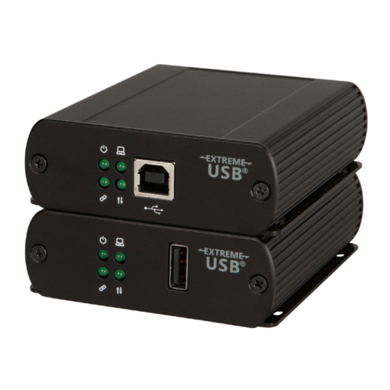
The Local Extender The local extender unit connects to the computer using a standard USB 2.0 cable. Power for this unit is provided by the host computer. Front View Rear View ITEM TYPE DESCRIPTION Power LED (Green) LED turns on when power is supplied. LED is off when no power is supplied by the host computer. -
Page 6: The Remote Extender
The Remote Extender The remote extender unit provides one USB Type A port for standard USB devices and allows you to connect one USB device directly. Additional devices may be connected by attaching up to four USB hubs to the remote extender unit. -
Page 7: Installation Guide
Installation Guide Installing the RG2301 Series as Direct Connect Requirements To complete the installation, you will also require the following items that are not included with this system: • USB compatible computer (host computer) with a USB compliant operating system •... -
Page 8: Installing The Local Extender
Installing the Local Extender Place the local extender near the computer. Connect the supplied USB cable between the local extender host port and a USB port on the host computer. Connecting the Local Extender to the Remote Extender With Surface Cabling: Connect the CAT 5e/6/7 cable into the Link port of the local extender. -
Page 9: Local Area Network Intallation (Rg2301N, 2301S & 2301Ge-Lan Models Only)
Local Area Network Installation (RG2301N, 2301S and 2301GE-LAN models only) Requirements To complete the installation, you will also require the following items that are not included with this system: • USB compatible computer (host computer) with a USB compliant operating system •... -
Page 10: Preparing Your Site
Preparing Your Site Before installing the RG2301N/2301S/2301GE-LAN, you will need to prepare your site: Place the computer where desired and set it up. Ensure to locate the USB device(s) within 100m of CAT 5e/6/7 cabling of the switch. Ensure to locate the computer within 100m of CAT 5e/6/7 cabling of the switch. note The cable distance between switches must be no greater than 100m. -
Page 11: Checking The Installation
Checking the Installation On the local and remote extender, check that the Power, Activity, Link and Host LEDs are on. For direct connect, if the Host or Link LEDs are permanently off, then the cabling between the local • and remote extender may not be installed properly or is defective. For network connect (RG2301N/2301S/2301GE-LAN models only), if the Link LED is blinking, then •... -
Page 12: Connecting A Usb Device
Compatibility The USB 2.0 RG2301 Series complies with USB 1.1 and USB 2.0 specifications governing the design of USB devices. However, there is no guarantee that all USB devices or hosts will be compatible as there are a number of different characteristics that may impact the operation of USB devices over extended distances. -
Page 13: Optional Usb Extender Mounting Options
Optional USB Extender Mounting Options The bottom of the RG2301 Series enclosures feature four convenient pre-drilled holes for optional direct surface mounting and four mounting slots for easy cable-ties. Based on your requirements, choose from three available mounting options: 1. USB Extender Mounting Kit 2. -
Page 14: Option 2: Usb Extender Direct Surface Mounting
Option 2: USB Extender Direct Surface Mounting (using your own hardware) The bottom of the RG2301 Series enclosures feature four pre-drilled holes for optional direct surface mounting. Using the stencil below, along with your own hardware you can directly mount your USB Extender on a surface. -
Page 15: Troubleshooting
Troubleshooting The following table provides troubleshooting tips. The topics are arranged in the order in which they should be executed in most situations. If you are unable to resolve the problem after following these instructions, please contact Technical Support for further assistance. PROBLEM CAUSE SOLUTION... - Page 16 PROBLEM CAUSE SOLUTION Link LED on the • The extenders are paired with 1. Wait for a few minutes for the LEDs to go solid. local and the each other but have not yet remote extenders established a link. 2. If LEDs do not go solid, contact your network are blinking slowly.
-
Page 17: Contacting Technical Support
Contacting Technical Support If you are experiencing problems not referenced in the Troubleshooting Guide, contact Technical Support at the company where you purchased this product and provide them with the following information: • Host computer make and mode • Type of operating system installed (e.g. Windows 8.1, Windows 10, OS X 10.11, etc.) •... -
Page 18: Technical Glossary
Technical Glossary Category 5e/6/7 (CAT 5e/6/7) Network Cabling Category 5e/6/7 cable is commonly also referred to as CAT 5e or CAT 6 or CAT 7. This cabling is available in either solid or stranded twisted pair copper wire variants and as UTP (Unshielded Twisted Pair) or STP (Shielded Twisted Pair). -
Page 19: Specifications
Specifications RANGE Direct Connect Up to 100m (330 ft) over solid core CAT 5e/6/7 Network Connect Up to 100m (330 ft) between switches over solid core CAT 5e/6/7 USB DEVICE SUPPORT Maximum Throughput Up to 480 Mbps* Traffic Types All Traffic Types Device Types All Device Types Maximum Number...
Need help?
Do you have a question about the USB 2.0 RG2301 and is the answer not in the manual?
Questions and answers