Viega Megapress Instructions For Use Manual
Press connectors for thick-walled steel pipes and the corresponding press tools
Hide thumbs
Also See for Megapress:
- Installation manual (28 pages) ,
- Installation manual (45 pages) ,
- Product instructions (4 pages)
Table of Contents
Advertisement
Advertisement
Table of Contents

Related Manuals for Viega Megapress


Summary of Contents for Viega Megapress
- Page 1 Megapress Instructions for Use Year built: from 10/2014 en_INT...
- Page 2 Megapress 2 from 32...
-
Page 3: Table Of Contents
3.3.3 Permitted exchange of sealing elements 3.3.4 Space requirements and intervals 3.3.5 Required tools Assembly 3.4.1 Replacing the sealing element 3.4.2 Shortening the pipes 3.4.3 Deburring the pipes 3.4.4 Pressing the connection 3.4.5 Leakage test Disposal Megapress 3 from 32... -
Page 4: About These Instructions For Use
This restriction does not extend to possible operating instructions. The installation of Viega products must take place in accordance with the general rules of engineering and the Viega instructions for use. -
Page 5: About This Translated Version
German/European directives specified in this manual: The information herein is not binding for other countries and regions; as said above, they should be understood as a recommendation. Megapress 5 from 32... -
Page 6: Product Information
2 Product information Standards and regulations The following standards and regulations apply to Germany / Europe. National regulations can be found on the relevant web site of your viega.com/standards . country at Regulations from section: Fields of application Scope / Notice... -
Page 7: Intended Use
VdS CEA 4001, Chapter 17 Requirements in filling and top-up VDI 2035 water Intended use Agree the use of the system for areas of use and media other than those described with the Viega Service Center. Megapress 7 from 32... -
Page 8: Areas Of Use
EPDM at oil concentration < 25 mg/m Anti-freeze, cooling brines up to a concentration of 50 % technical gases (on request) Product description 2.3.1 Overview The piping system consists of press connectors for thick-walled steel pipes and the corresponding press tools. Megapress 8 from 32... -
Page 9: Pipes
D ⅜ (DN 10), D ½ (DN 15), D ¾ (DN 20), D 1 (DN 25), D 1¼ (DN 32), D 1½ (DN 40), D 2 (DN 50). 2.3.2 Pipes Megapress press connectors may be used with the following seam- less (S) or longitudinal welded (W) steel pipes: black galvanised... - Page 10 [mm] diameter incl. diameter incl. [mm] coating [mm] coating [mm] ⅜ 17.2 16.7 17.1 ½ 21.3 21.0 21.4 ¾ 26.9 26.4 26.9 33.7 33.2 33.8 1¼ 42.4 41.9 42.5 1½ 48.3 47.8 48.4 60.3 59.6 60.2 Megapress 10 from 32...
- Page 11 Interval between the pipe clamps D [mm] Nominal width Fixing interval Fixing interval [inch] between between the pipe clamps the pipe clamps 17.2 ⅜ 2.25 — ½ 21.3 2.75 — Ä „Regulations from section: Pipes“ on page 6 Megapress 11 from 32...
- Page 12 Expansion equalisation joints (expansion bends) Compensators Heat expansion co-efficients of various pipe materials Material Heat expansion co-effi- Example: cient ⍺ Length expansion with [mm/mK] pipe lengths L = 20 m and ΔT = 50 K [mm] Steel 0.0120 12.0 Megapress 12 from 32...
-
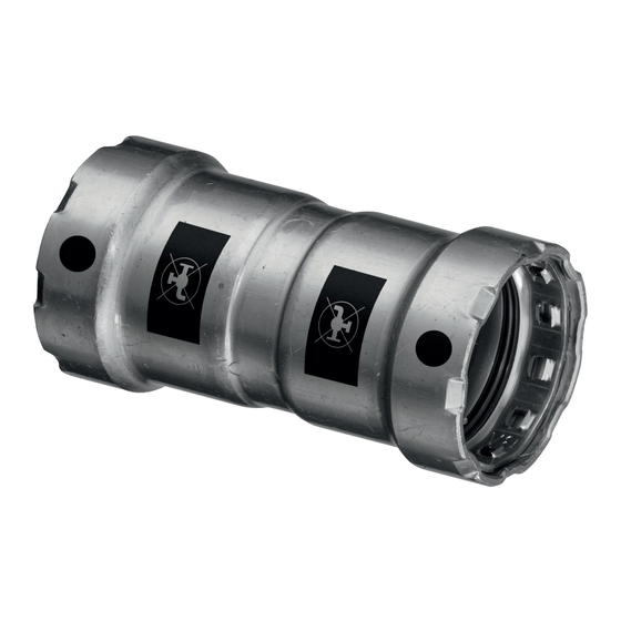
Page 13: Press Connectors
Δl = ⍺ [mm/mK] × L [m] x Δϑ [K] 2.3.3 Press connectors Press connectors are available in a number of shapes. An overview of the press connectors suitable for the system can be found in the cata- logue. Megapress 13 from 32... - Page 14 Product information Fig. 4: Press connectors The Megapress press connectors consist of non-alloy steel (mate- rial 1.0308) and have an external high-quality 3–5 µm zinc-nickel coating. There is a cutting ring, a separator ring and a profile sealing element in the bead of the press connector. The cutting ring cuts into the pipe during pressing and ensures a force-fit connection.
-
Page 15: Sealing Elements
105 °C < 25 mg / m with radiator con- nections T : 95 °C Consultation with the Viega Service Center required Ä „Regulations from section: Sealing elements“ on page 6 2.3.5 Markings on components Markings on press connectors The press connectors are marked with a coloured dot. This identifies the SC-Contur, where the test medium would escape in the case of an inadvertently unpressed connection. -
Page 16: Information For Use
Fig. 7: Inscription "Not suitable for drinking water" Information for use 2.4.1 Corrosion A zinc-nickel coating protects Megapress press connectors against external corrosion, e. g. in the case of arising condensation water in cooling systems. Pipes must be equipped with suitable corrosion protection. -
Page 17: Handling
Assembly information 3.3.1 Mounting instructions Checking system components System components may, in some cases, become damaged through transportation and storage. Check all parts. Replace damaged components. Do not repair damaged components. Contaminated components may not be installed. Megapress 17 from 32... - Page 18 VdS Ä „Regulations from section: Notes on mounting“ on page 7 The following fire hazard classes are covered by Megapress: Fire hazard class LH (light hazard) Fire hazard class OH 1–4 (ordinary hazard) Fire hazard class HHP 1–4 (extra hazard, production risks) Fire hazard class HHS 1–4 (extra hazard, storage risks)
- Page 19 „Pipes“ on page 9 ) industrially painted or powder-coated (maximum external diameter in Ä Chapter 2.3.2 „Pipes“ on page 9 ) acc. with Pipe surfaces must be treated around the press connection if they exhibit the following characteristics: Megapress 19 from 32...
- Page 20 Exceeding the maximum external diameter due to coating that has been added Ä Chapter 2.3.2 „Pipes“ on page 9 Bumps, damage, grooves, corrosion or loose adhesions The following are examples of suitable tools for the work: Wire brush Megapress 20 from 32...
- Page 21 After the treatment, the quality of the pipe surface should be as shown in the following graphic: In systems where complete corrosion protection is required (e. g. cooling systems), subsequently apply suitable corrosion protection to the previously processed pipe surfaces that are still uncovered after pressing. Megapress 21 from 32...
-
Page 22: Potential Equalisation
„Sealing elements“ on page 15. The use of other sealing elements is not permitted. If the profile sealing element in the press connector is obviously dam- aged, it should be exchanged for a Viega replacement profile sealing element made of the same material. 3.3.4... - Page 23 Pressing between pipe and wall Space requirement PT1, Type 2 (PT2), PT3-EH, PT3-AH, Pressgun 4B, 4E, 5 ½ ¾ ⅜ a [mm] b [mm] c [mm] Space requirement Picco, Pressgun Picco ½ ¾ ⅜ a [mm] b [mm] c [mm] Megapress 23 from 32...
- Page 24 If two press connectors are to be mounted onto a pipe without an interval, the pipe must not be too short. If the pipe is not inserted up to the prescribed insertion depth in the press connector during pressing, the connection may become leaky. Megapress 24 from 32...
-
Page 25: Required Tools
3.3.5 Required tools NOTICE! Megapress connectors may only be pressed with Mega- press press rings and jaws. Press rings and jaws from the metallic Viega press connector systems Profipress, San- press, Sanpress Inox and Prestabo may not be used. - Page 26 (D ⅜–1) or press ring (D½– 2) with corresponding adapter jaw, suitable for the pipe diameter and with the proper profile Fig. 8: Megapress press jaws Fig. 9: Megapress press rings Megapress...
-
Page 27: Assembly
Handling Recommended Viega press machines: Pressgun 5 Pressgun Picco Pressgun 4E / 4B Picco Type PT3-AH Type PT3-H / EH Type 2 (PT2) Assembly 3.4.1 Replacing the sealing element CAUTION! Risk of injury due to sharp edges There is a sharp-edged cutting ring above the sealing ele- ment (see arrow). -
Page 28: Shortening The Pipes
The pipe ends must be thoroughly deburred internally and externally after shortening. Deburring prevents the sealing element being damaged or the that the press connector cants when mounted. Use of a deburrer is recom- mended. ≤ D 1½ (model 2292.2) D 2 (model 2292.4XL) Megapress 28 from 32... -
Page 29: Pressing The Connection
The pipe ends must not be bent or damaged. Deburr the inside and outside of the pipe. 3.4.4 Pressing the connection With the help of a wire brush, cleaning fleece or sandpaper, remove loose dirt and rust particles from the pressing area. Megapress 29 from 32... - Page 30 Measure insertion depth. Insertion depth [mm] ⅜ ½ ¾ 1¼ 1½ Mark the insertion depth. Push the press connector up to the marked insertion depth on the pipe. Do not twist the press connector. Megapress 30 from 32...
- Page 31 Check the insertion depth using the marking. Ensure that the press ring is placed centrally on the bead of the press connector. Carry out the pressing process. Open the adapter jaw and remove the press ring. Megapress 31 from 32...
-
Page 32: Leakage Test
Ä „Regu- lations from section: Leakage test“ on page 7. Disposal Separate the product and packaging materials (e. g. paper, metal, plastic or non-ferrous metals) and dispose of in accordance with valid national legal requirements. Megapress 32 from 32...
Need help?
Do you have a question about the Megapress and is the answer not in the manual?
Questions and answers