Table of Contents
Advertisement
Quick Links
Introduction
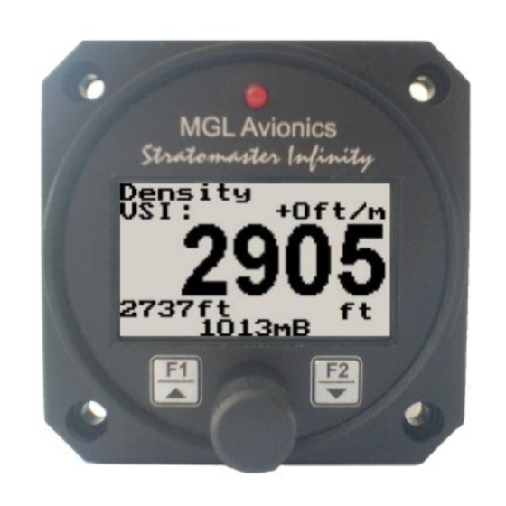
The ALT-1 is a 2 1/4" instrument that contains a precision encoding altimeter and a wide range vertical speed indicator.
The altimeter conforms to ANSI standard atmosphere rules from –1000 ft up to a maximum of 30 000 ft. The altimeter
includes an encoding serial output that when used in combination with MGL Avionics CNV-AT, provides a parallel Gillham
code interface for transponders. The altimeter can display altitude in feet or meters, local pressure can be set in millibars
or inches of mercury
The onboard VSI indicator is altitude compensated and can be displayed in either feet/minute (ft/min) or meters/second
(m/s). It also offers a digital readout with a wide range from +/-20 ft/min to as high as +/-10 000 ft/min, it also offers a
logarithmic analog display with a +/-2000 ft range. The VSI can be calibrated by the user once the instrument has been
installed in the aircraft.
In addition the ALT-1 provides an OAT sender which is used in determining the density altitude of the aircraft. The ALT-1
can also be used to measure relative altitude and it has a facility for the pilot to enter a reference altitude and deviation
band that has to be kept.
1 Features
•
Precision altimeter from –1000 ft up to a maximum of 30 000 ft (-304m to 9144m)
•
Provides altitude encoder data on airtalk (serial) output, which can be converted by a MGL Avionics CNV-
AT converter to a parallel Gillham code interface for transponders
•
The altimeter can display altitude in feet or meters, local pressure can be set in millibars or inches of
mercury
•
Contains a wide range VSI indicator from +/-20 ft/min to as high as +/-10 000 ft/min
•
VSI units can be in feet/minute (ft/min) or in meters/second (m/s)
•
Records the maximum and minimum OAT (outside air temperature) and maximum altitude reached in
permanent memory
•
Records maximum and minimum OAT in temporary memory since instrument power up
•
Standard 2 1/4" aircraft enclosure (can be front or rear mounted)
•
Rotary control plus 2 independent buttons for easy menu navigation and user input
•
Alarm output as well as a red LED illuminates when the alarm has been activated
•
Large backlit graphic LCD with adjustable contrast
•
Wide input supply voltage range of 8 to 30V DC with built in voltage reversal and over voltage protection
for harsh electrical environments
•
Light weight design
•
Field upgradeable firmware
•
1 year limited warranty
ALT-1
Precision Encoding Altimeter and
Vertical speed indicator (VSI)
Operating Manual – English 1.09
Advertisement
Table of Contents

Subscribe to Our Youtube Channel
Related Manuals for MGL Avionics ALT-1


Summary of Contents for MGL Avionics ALT-1
- Page 1 In addition the ALT-1 provides an OAT sender which is used in determining the density altitude of the aircraft. The ALT-1 can also be used to measure relative altitude and it has a facility for the pilot to enter a reference altitude and deviation band that has to be kept.
-
Page 2: Main Display
3 Main Display The main displays can be toggled by pressing the F2/Down key. 3.1 Altitude and VSI display This is the standard display for the ALT-1. Use the rotary control to adjust the local pressure setting. Altitude relative to Logarithmic analog... - Page 3 Altitude unit Local pressure readout (either in millibars or in inches of mercury) 3.3 VSI (Vertical Speed Indicator) The ALT-1 can be setup to be as a VSI (vertical speed indicator). Digital VSI readout Logarithmic analog VSI indicator VSI units 3.4 Deviation Altitude display...
- Page 4 ALT-1 Operating Manual Page 4 Use the rotary control to adjust the local pressure setting. Pressing the F1/up key will allow the pilot to enter a reference altitude and the deviation band. Adjust the reference altitude using the rotary control. This is the altitude that the pilot wants to maintain.
-
Page 5: Menu System
OAT reading Temperature unit 4 Menu System Pressing the rotary control button during the normal display mode will cause the ALT-1 to enter the menu system. Use the up/down keys or the rotary control to navigate through the menu system. -
Page 6: Maximum Values
4.1 Exit Menu Pressing the rotary control on this menu item will cause the ALT-1 to exit the menu system. All changes made during navigation of the menu system will be saved in non-volatile memory on exiting the menu system. - Page 7 ALT-1 Operating Manual Page 7 Select this menu option to turn the backlight on or off. Select whether you want the OAT to be displayed in degress Fahrenheit (ºF) or in degrees Celcius (ºC). 4.4 Altitude Setup All altitude related parameters can be setup here.
-
Page 8: Adc Values
ALT-1 Operating Manual Page 8 Select if you want to show the built in VSI (vertical speed indicator). The built in VSI will be shown above the altitude readout. Select if you want your VSI readout in feet/minute (ft/m) or meters/second (m/s). -
Page 9: Altitude Encoder
To use the ALT-1 as an encoding altimeter an Airtalk to parallel Gillham code output encoder such as the MGL Avionics CNV-AT must be used. This converter takes the Airtalk serial string that is outputted by the ALT-1 and converts it to a parallel Gillham code suitable for aircraft transponders. -
Page 10: Installation
You will need to install a suitable static port in these cases. The use of an external 1A fuse is recommended. Connect the supply terminals to your aircrafts power supply. The ALT-1 can be used on both 12V and 24V without the use of any pre-regulators. -
Page 11: Connection Diagram
ALT-1 Operating Manual Page 11 10.2 Connection Diagram 10.3 Pressure Port Dimensions Inches Millimeters 0.182 0.194 4.62 4.93 0.420 0.440 10.67 11.18 11 Warranty This product carries a warranty for a period of one year from date of purchase against faulty workmanship or defective materials, provided there is no evidence that the unit has been mishandled or misused. - Page 12 ALT-1 Operating Manual Page 12 12 Disclaimer Operation of this instrument is the sole responsibility of the purchaser of the unit. The user must make themselves familiar with the operation of this instrument and the effect of any possible failure or malfunction.
- Page 13 ALT-2 Precision Encoding Altimeter and Vertical speed indicator (VSI) with a serial RS232 transponder output Operating Manual – English 1.05 Introduction The ALT-2 is a 2 1/4” instrument that contains a precision encoding altimeter and a wide range vertical speed indicator. The altimeter conforms to ANSI standard atmosphere rules from –1000 ft up to a maximum of 30 000 ft.
- Page 14 ALT-2 Operating Manual Page 2 2 ALT-2 Layout LED Alarm: The red LED will illuminate if the deviation band has been exceeded when using the deviation altitude mode Backlit Graphic LCD Display: Contrast and backlight can be adjusted Pressure Ports: in the menu system Pressure ports connect to the static pressure...
- Page 15 ALT-2 Operating Manual Page 3 3.2 Altitude relative to sea level display Use the rotary control to adjust the local pressure setting. Altitude relative to Digital VSI readout, mean sea level can be turned off in the menu system Barometer, can be turned off in the menu system Altitude unit...
- Page 16 ALT-2 Operating Manual Page 4 Use the rotary control to adjust the local pressure setting. Pressing the F1/up key will allow the pilot to enter a reference altitude and the deviation band. Adjust the reference altitude using the rotary control. This is the altitude that the pilot wants to maintain.
- Page 17 ALT-2 Operating Manual Page 5 Da = Density altitude Pa = Pressure altitude T = ambient temperature in degrees C Ts= 15 - 0.0019812 * pressure altitude (ft) Da = Pa + 118.6 * (T-Ts) Compensated Digital VSI readout, density altitude can be turned off in value the menu system...
- Page 18 ALT-2 Operating Manual Page 6 Note: (ADC Values and Calibrate Menus are only visible when powering up the unit and pressing the Rotary Control). The text “CALIBRATE” will appear on the intro screen when entering this mode. Warning: The Calibrate Menu is for technical personnel only. Changing any values in this menu may cause the instrument to display incorrect information, and may require the instrument to be returned to the factory for recalibration.
- Page 19 Select if you want the barometer to be displayed on the altitude screens or not. Select the protocol of the RS232 output message. The protocol can be selected between GARMIN AT, Magellan, Northstar/Garmin, Trimble/Garmin, MGL Avionics and Microair UAV. Please see section 5 for more information.
- Page 20 ALT-2 Operating Manual Page 8 Move the highlight over the “DONE” menu item and press the rotary button to return to the main menu. This function is used to set your VSI to read exactly 0ft/min. This is similar to setting the needle on a mechanical VSI to point to zero by turning the adjustment knob on such a VSI.
-
Page 21: Protocol Baud Rate
Trimble, Garmin 9600 ALT, space, five altitude digits right justified ALT 02372[CR] zero padded, carriage return MGL Avionics 9600 ALT, +/-, five altitude digits right justified ALT+02372C+02372L1013+0000XCA[CR] zero padded ,1013.25mB (29.92”Hg) referenced, C, +/-, five altitude digits right... -
Page 22: Loading Factory Default Settings
ALT-2 Operating Manual Page 10 justified zero padded (corrected to local pressure), L, local pressure setting in millibars,+/-, four digit VSI reading right justified zero padded in ft/min, X, checksum, carriage return The checksum is a simple modulo 256 sum of the binary values of the individual characters. -
Page 23: Installation
ALT-2 Operating Manual Page 11 9 ALT-2 Specifications Operating Temperature Range -10ºC to 50ºC (14ºF to 122ºF) Storage Temperature Range -20ºC to 80ºC (-4ºF to 176ºF) Humidity <85% non-condensing 8 to 30Vdc SMPS (switch mode power supply) with built in 33V over Power Supply voltage and reverse voltage protection Current Consumption... - Page 24 ALT-2 Operating Manual Page 12 10.2 Connection Diagram 10.3 ALT-2 DB9 Cable connections DB 9 Pin Color Function Black Ground Orange OAT Sensor Green RS232 Output to transponder Airtalk communication (Not connected) Used for firmware upgrading 8-30Vdc power White Alarm Output 10.4 Pressure Port Dimensions Inches Millimeters...
- Page 25 Under no circumstances does the manufacturer condone usage of this instrument for IFR flights. The manufacturer reserves the right to alter any specification without notice. Other instruments in the Stratomaster Infinity series ALT-1 Precision encoding altimeter and vertical speed indicator ALT-2 Precision encoding altimeter and vertical speed indicator with a serial RS232...
- Page 26 ASI-1 Airspeed Indicator (ASI) with automatic flight log Operating Manual – English 1.06 Introduction The ASI-1 airspeed indicator is a 2 1/4” instrument that provides a wide range airspeed indication in both digital and analog formats. Airspeed is based on the pressure generated by a pitot tube system and a static port is provided as well for use by high speed aircraft.
-
Page 27: Main Display
ASI-1 Operating Manual Page 2 2 ASI-1 Layout LED Alarm: The red LED will illuminate if the airspeed alarm set-point has been exceeded Backlit Graphic LCD Display: Contrast and backlight can be adjusted in the menu system Pressure Ports: Pressure ports connect to static and pitot tubes Harness: Harness connects to... - Page 28 ASI-1 Operating Manual Page 3 3.1 Start/Stop Flight Display Press the F1 key during the normal display mode to manually start/stop a flight. This key is only active if the ASI-1 is setup to select the manual flight option under the “Flight Log” setup menu. 3.2 Reset Air Distance Trip Counter Display This display can be accessed by pressing the F2 key during the normal display mode.
-
Page 29: Flight Log
ASI-1 Operating Manual Page 4 4 Menu System Pressing the rotary control button during the normal display mode will cause the ASI-1 to enter the menu system. Use the up/down keys or the rotary control to navigate through the menu system. Note: (ADC Values and Calibrate Menus are only visible when powering up the unit and pressing the Rotary Control). - Page 30 ASI-1 Operating Manual Page 5 Select this function to view the flight log. The flight log contains the duration of each of the last 24 logged flights. Duration is displayed in hours and minutes. Use the up/down keys or the rotary control to navigate through the log. Empty log entries are shown as “-----“.
- Page 31 ASI-1 Operating Manual Page 6 4.4 Airspeed Setup All the airspeed parameters can be setup here Move the highlight over this menu option and press the rotary button to return to the main menu This setup allows your instrument to measure the zero airspeed reading of the airspeed sensor and set a calibration value internally for this.
- Page 32 ASI-1 Operating Manual Page 7 You can set up a marker on the analog airspeed display for Vs. Vs would be your stall speed or minimum safe flying speed. You may also choose to use this marker as your approach speed. You can set up a marker on the analog airspeed display for Vf.
-
Page 33: Specifications
ASI-1 Operating Manual Page 8 5 Loading Factory default settings Pressing and holding the F1 and F2 key simultaneously on power up will cause the ASI-1 to load preprogrammed factory default settings. The following screen will be displayed: 6 Operating the alarms If the alarm is activated, the corresponding item on the display will flash. - Page 34 ASI-1 Operating Manual Page 9 9 Installation Connect a pitot tube to the “pressure port” and if required connect the static port. Pitot tubes are found in a large variety at your aircraft parts shop, in mail order catalogs or you can make your own. Contrary to popular belief, pitot tubes are not carefully designed and calibrated but are simple orifices or tubes that get pointed in the direction that you are flying.
- Page 35 ASI-1 Operating Manual Page 10 9.3 Connection Diagram The use of an external 1A fuse is recommended. Connect the supply terminals to your aircrafts power supply. The ASI-1 can be used on both 12V and 24V without the use of any pre-regulators. Ensure that the supply voltage will not drop below 8V during operation as this may result in incorrect voltage and or current readings.
- Page 36 Under no circumstances does the manufacturer condone usage of this instrument for IFR flights. The manufacturer reserves the right to alter any specification without notice. Other instruments in the Stratomaster Infinity series ALT-1 Precision encoding altimeter and vertical speed indicator ALT-2 Precision encoding altimeter and vertical speed indicator with a serial RS232...
- Page 37 The altimeter conforms to ANSI standard atmosphere rules from –1000 ft up to a maximum of 30 000 ft.The altimeter includes an encoding serial output that, when used in combination with MGL Avionics CNV-AT, provides a parallel Gillham code interface for transponders. The altimeter can display altitude in feet or meters. Local pressure can be set in millibars or inches of Mercury.
- Page 38 ASX-1 Operating Manual Page 2 2 ASX-1 Layout LED Alarm: The red LED will illuminate if the airspeed alarm set points has been exceeded Backlit Graphic LCD Display: Contrast and backlight can be adjusted in the menu system Pressure Ports: Pressure ports connect to static and pitot tubes Harness:...
- Page 39 ASX-1 Operating Manual Page 3 3.1 Start/Stop Flight display Press the F1 key during the normal display mode to manually start/stop a flight. This key is only active if the ASX-1 is setup to select the manual flight option under the log book setup menu. 3.2 Flight time and air distance display This display can be accessed by pressing the F2 key during the normal display mode.
- Page 40 ASX-1 Operating Manual Page 4 Note: (ADC Values and Calibrate Menus are only visible when powering up the unit and pressing the Rotary Control). The text “CALIBRATE” will appear on the intro screen when entering this mode. Warning: The Calibrate Menu is for technical personnel only. Changing any values in this menu may cause the instrument to display incorrect information, and may require the instrument to be returned to the factory for recalibration.
- Page 41 ASX-1 Operating Manual Page 5 Select this function to view the flight log. The flight log contains the duration of each of the last 24 logged flights. Duration is displayed in hours and minutes. Eight flights are displayed at a time, Use the up/down or the rotary control to navigate through the log.
- Page 42 ASX-1 Operating Manual Page 6 4.5 Altitude Setup Move the highlight over this menu item and press the rotary button to return to the main menu. Select if you want your altitude readout in feet (ft) or meters (m). Select if you want your local pressure readout in millibars (mB) or inches of Mercury (“Hg). Select whether you want the altitude display on the top or on the bottom of the main display.
- Page 43 ASX-1 Operating Manual Page 7 Enter the low airspeed set-point for when the alarm must activate. Any speed below this value will activate the alarm. Select whether you want the low air speed alarm to be turned on or off. The low airspeed alarm is only activated once a flight has started.
-
Page 44: True Airspeed (Tas)
5 Altitude Encoder To use the ASX-1 as an encoding altimeter an Airtalk to parallel Gillham code output encoder such as the MGL Avionics CNV-AT must be used. This converter takes the Airtalk serial string that is outputted by the ASX-1 and converts it to a parallel Gillham code suitable for aircraft transponders. - Page 45 ASX-1 Operating Manual Page 9 7 Loading factory default settings Pressing and holding the F1 and F2 simultaneously on power up will cause the ASX-1 to load preprogrammed factory default settings. The following screen will be displayed: 8 Operating the alarms If the alarm is activated, the corresponding item on the display will flash.
- Page 46 ASX-1 Operating Manual Page 10 11 Installation Connect the static port to a suitable static air pressure line. If you have a slow aircraft or an aircraft were the internal cabin pressure does not change during flight and is equivalent to the outside air pressure you may find that it is not required to connect a static port.
- Page 47 ASX-1 Operating Manual Page 11 11.2 Connection Diagram Connect static port to suitable static line on the aircraft. Note: Leaving this port unconnected may lead to airspeed and altitude errors as cabin pressure changes due to airflow or other factors. Connect the pressure port to a pitot tube. The location of the pitot tube should be chosen so it is exposed to clean, undisturbed airflow at the same speed as the aircraft if flying.
-
Page 48: Warranty
Under no circumstances does the manufacturer condone usage of this instrument for IFR flights. The manufacturer reserves the right to alter any specification without notice. Other instruments in the Stratomaster Infinity series ALT-1 Precision encoding altimeter and vertical speed indicator ALT-2 Precision encoding altimeter and vertical speed indicator with a serial RS232... - Page 49 The AV-1 is a 2 1/4” instrument that can be used as a display interface for an artificial horizon reference system (AHRS), advanced digital compass, or both depending on which MGL Avionics sensor packages is connected to the AV-1. The AV-1 can be setup to display the following: •...
- Page 50 Infinity AV-1 Operating Manual Page 2 2 Layout LED alarm: The red LED will illuminate if the artificial horizon has exceeded its Backlit graphic LCD display: maximum rate of bank, pitch or yaw Contrast and backlight can be adjusted in the menu system Harness: Harness connects to power and airtalk bus.
-
Page 51: Turn And Bank Indicator
Infinity AV-1 Operating Manual Page 3 3.1 Artificial Horizon with Compass 10 degree pitch bars Magnetic (M) or true heading (T) indicator Mini turn and bank indicator (can be switched on or off in the menu system) Magnetic or true heading reading (compass can be switched on or off in the menu system) -
Page 52: Digital Compass
Infinity AV-1 Operating Manual Page 4 Extended range of operation Bank operates over a full 360 degree range allowing unlimited use of the horizon for aerobatics, provided that the maximum published bank, pitch and yaw rates are not exceeded. Please see the corresponding MGL sensor documentation for maximum rate specifications. - Page 53 Infinity AV-1 Operating Manual Page 5 3.3.3 Cardinal 1 compass display The heading tape shows headings as major and minor cardinal points: N, NNE, ENE, E, ESE, SSE, S, SSW, WSW, W, WNW, and NNW. Magnetic (M) or true (T) North indicator Please see the table under section 4.4 for more information...
- Page 54 Infinity AV-1 Operating Manual Page 6 The current heading is 85 degrees; course steering indicators show the need to steer slightly to the right to intercept the course. The current heading is 42 degrees; course steering indicators show that a large correction to the right is required to intercept the course.
-
Page 55: Menu System
Infinity AV-1 Operating Manual Page 7 4 Menu System Pressing the rotary control button during the normal display mode will cause the AV-1 to enter the menu system. Use the up/down keys or the rotary control to navigate through the menu system. 4.1 Exit Menu Pressing the rotary control on this menu item will cause the AV-1 to exit the menu system. - Page 56 Infinity AV-1 Operating Manual Page 8 Move the highlight over the “DONE” menu item and press the rotary control to return to the main menu. Select if you would like to enable the slip indicator to be shown underneath the horizon display. The slip indicator operates in the same fashion as the well known “step on the ball”...
-
Page 57: Compass Setup
Infinity AV-1 Operating Manual Page 9 4.4 Compass Setup All compass related parameters are set up here. Move the highlight over the “DONE” menu item and press the rotary control to return to the main menu Select whether you want the mini compass to be shown on the horizon display screen. Select if you are using "GROUND"... - Page 58 Infinity AV-1 Operating Manual Page 10 Do not activate any electrical equipment that creates large magnetic fields during the calibration process (for example starter motors, autopilot servos, landing lights etc). The heading starts reading 111 after you start calibration. After 36 initial samples have been collected this changes to 222.
- Page 59 Infinity AV-1 Operating Manual Page 11 accelerometers. Can show very large errors if the horizon information is invalid which Can provide for accurate heading even during turns as tilt 3D-G could have a number of causes such compensation is based on gyro derived horizon. as exceeding operational limitations of the horizon system.
- Page 60 Infinity AV-1 Operating Manual Page 12 Once you have completed your turn(s), press the F2 key again to inform the instrument that you have finished. Your instrument will at this point calculate the best possible fit of the sensor data to a 360 degree arc taking the relative strengths and offsets of the magnetic field into account.
-
Page 61: Loading Factory Default Settings
2 1/4” ABS, black in color, front or rear mounting Weight Approx. 106 grams Non-volatile memory storage 100000 write cycles Airtalk protocol 19200 baud, 8 data bits, no parity, 1 stop bit (TTL voltage levels) Compass Sensors: SP-2/6 MGL Avionics sensor packages Attitude Sensors: SP-3/4/5/7... -
Page 62: Installation
Infinity AV-1 Operating Manual Page 14 10 Installation Note: Please see corresponding SP-X sensor package manuals for more information about the installation and use of the artificial horizon and compass. 10.1 Connection Diagram The use of an external 1A fuse is recommended. The AV-1 can be used on both 12V and 24V without the use of any pre- regulators (Please make sure you use a pre-regulator if you intend operating the SP-X sensor package from a 24Vdc power source). - Page 63 Infinity AV-1 Operating Manual Page 15 SP-5 Attitude Sensor package. SP-6 Compass SP-7 Attitude sensor package 10.2 DB9 Cable connections DB 9 Pin Color Function Black Ground Purple Airtalk communication link 8-30Vdc power...
-
Page 64: Warranty
Under no circumstances does the manufacturer condone usage of this instrument for IFR flights. The manufacturer reserves the right to alter any specification without notice. Other instruments in the Stratomaster Infinity series ALT-1 Precision encoding altimeter and vertical speed indicator ALT-2 Precision encoding altimeter and vertical speed indicator with a serial RS232... - Page 65 BAT-1 Battery voltage and current monitor Operating Manual – English 1.05 Introduction The BAT-1 is a 2 1/4” instrument used to monitor your aircraft’s battery power supply. It can be used on lead-acid, NiCad batteries as well as gel cells. This instrument is very useful in determining your battery’s health, charging status, as well as the current load consumption of your aircraft.
-
Page 66: Main Display
BAT-1 Operating Manual Page 2 2 BAT-1 Layout LED Alarm: The red LED will illuminate if the voltage alarm set-point has been exceeded Backlit Graphic LCD Display: Contrast and backlight can be adjusted in the menu system Harness: Harness connects to power and the current shunt Up/F1 Button:... - Page 67 BAT-1 Operating Manual Page 3 Voltage Only Voltage display Maximum voltage reached Current Only Current display Charge/Discharge icon Current analog bar graph Maximum current reached indicator Current span 3.1 Contrast Display This display can be accessed by pressing the F2 key during the normal display mode. This is a quick access key to the same contrast menu in the menu system.
-
Page 68: Menu System
BAT-1 Operating Manual Page 4 4 Menu System Pressing the rotary control button during the normal display mode will cause the BAT-1 to enter the menu system. Use the up/down keys or the rotary control to navigate through the menu system. 4.1 Exit Menu Pressing the rotary control on this menu item will cause the BAT-1 to exit the menu system. -
Page 69: Battery Setup
BAT-1 Operating Manual Page 5 Select whether you want the single voltage/current display to alternate automatically or manually This display is only shown if display mode is setup to show either voltage only or current only Set the time that the single display modes must be displayed for. This display is only shown if auto is selected for the display mode 4.3 Battery Setup All the battery voltage and shunt parameters can be setup here... - Page 70 BAT-1 Operating Manual Page 6 5 Loading Factory default settings Pressing and holding the F1 and F2 keys simultaneously on power up will cause the BAT-1 to load preprogrammed factory default settings. The following screen will be displayed: 6 Operating the alarms If the alarm is activated, the corresponding item on the display will flash.
- Page 71 BAT-1 Operating Manual Page 7 9 BAT-1 Specifications Operating Temperature Range -10ºC to 50ºC (14ºF to 122ºF) Storage Temperature Range -20ºC to 80ºC (-4ºF to 176ºF) Humidity <85% non-condensing 8 to 30Vdc SMPS (switch mode power supply) with built in 33V over voltage Power Supply and reverse voltage protection Current Consumption...
- Page 72 BAT-1 Operating Manual Page 8 The use of an external 1A fuse is recommended. Connect the supply terminals to your aircrafts power supply. The BAT-1 can be used on both 12V and 24V without the use of any pre-regulators. Ensure that the supply voltage will not drop below 8V during operation as this may result in incorrect voltage and/or current readings.
- Page 73 Infinity E-3 Universal Engine Monitor Operating Manual – English 1.10 Introduction The E-3 universal engine monitor combines in one compact 2 1/4” format instrument all that is needed to monitor the majority of smaller aircraft engines from two-stroke ultra-light engines to medium sized four strokes such as those from Rotax, Continental and Lycoming.
- Page 74 Infinity E-3 Operating Manual Page 2 2 E-3 Layout LED alarm: The red LED will illuminate if any of the alarm thresholds have been reached Backlit graphic LCD display: Contrast and backlight can be adjusted in the menu system Harness: Harness connects to power, EGT/CHT thermocouples and...
- Page 75 Infinity E-3 Operating Manual Page 3 3 Main Display The E-3 display can be customized to suite your engine measurement requirements. The E-3 will always try and maximize the display area in accordance to the measurement variables selected. The E-3 can be configured to how many EGT and CHT channels you want to display, and whether you want to display a temperature and/or pressure NTC input.
- Page 76 Infinity E-3 Operating Manual Page 4 3.2 Special Rotax 912/914 display mode In this mode the temperature and pressure NTC inputs becomes CHT channel one and CHT channel 2 respectively. All CHT setups must still be done under the “CHT SETUP” menu. The sender for the temperature and pressure setup must be set for “OFF”.
-
Page 77: Information Display
Infinity E-3 Operating Manual Page 5 3.4 Contrast Display This display can be accessed by pressing the F2 key during the normal display mode. This is a quick access key to the same contrast menu as in the menu system. 3.5 Maximum Values Display This display can be accessed by rotating the rotary control clockwise during the normal display mode. - Page 78 Infinity E-3 Operating Manual Page 6 4 Menu System Pressing the rotary control button during the normal display mode will cause the E-3 to enter the menu system. Use the up/down keys or the rotary control to navigate through the menu system. 4.1 Exit Menu Pressing the rotary control on this menu item will cause the E-3 to exit the menu system.
-
Page 79: Flight Log
Infinity E-3 Operating Manual Page 7 4.2 Flight Log Select whether the instrument should detect the start and end of flights automatically or if you would like to do this manually. We recommend you select automatic flight detect. With automatic flight detection, flights will start logging when the engine RPM is above the take-off limit. -
Page 80: Hobbs Meter
Infinity E-3 Operating Manual Page 8 4.4 Hobbs Meter Move the highlight over the “DONE” menu option and press the rotary button to return to the main menu. Enter the RPM limit in which the Hobbs meter/maintenance timer must start counting. This function allows you to set the engine Hobbs meter to any value. - Page 81 Select if you are using a K-type, J-type or E-type thermocouple probe for this channel. All probes supplied by MGL Avionics are K-Type. J-types are sometimes used with American made CHT probes. All EGT probes are K-type. E-type probes are seldom used.
- Page 82 Select if you are using a K-type, J-type or E-type thermocouple probe for this channel. All probes supplied by MGL Avionics are K-Type. J-types are sometimes used with American made CHT probes. All EGT probes are K-type. E-type probes are seldom used. If the probe type is set for “NTC”...
- Page 83 Infinity E-3 Operating Manual Page 11 Enter the RPM alarm activation threshold. Any RPM value above this value will activate the alarm. Enter the number of pulses per RPM. For engines with an uneven number of cylinders like three cylinder four stroke engines you can enter values containing fractions (usually 1.5 in this example). Most four stroke engines will generate one pulse for every two revolutions per cylinder.
-
Page 84: Pressure Setup
Infinity E-3 Operating Manual Page 12 10,20,30,40,50,60,70,80,90,100 – The filter factor can be set to any of these values independent of your scale selection. Choose a filter setting that results in a smooth, high resolution RPM display. A filter setting too low for your setup will result in a “jumpy”... -
Page 85: Temperature Setup
Infinity E-3 Operating Manual Page 13 Menu options for all sender types Choose one of a selection of labels to suit your pressure input so you can identify it easily. Select whether you want to display the pressure in Bar, PSI or PSI(0.1). The PSI(0.1) is for low range pressure senders e.g. - Page 86 Infinity E-3 Operating Manual Page 14 Select what type of sender you are using. Select “VDO” for VDO/NTC senders, “ECHLIN” (Echlin TS920SA temperature sender), LM335 for the MGL precision temperature sender or “USER” for a custom sender. The E-3 has a built in linearization curve for a standard 50ºC to 150ºC VDO sender as used in a Rotax 912 engine.
-
Page 87: Voltage Setup
Infinity E-3 Operating Manual Page 15 Use this to set the high temperature alarm set-point. 4.9.1 Calibrating the user defined pressure and temperature sender 1. Enter the number of points that you want to calibrate. 2. Enter the display reading that you want to show when the sender is at that actual display reading. - Page 88 Infinity E-3 Operating Manual Page 16 5 Engine configurations The E-3 supports 66 different engine configurations. See the table below. Pressure Temperature RPM Volts...
-
Page 89: Loading Factory Default Settings
Infinity E-3 Operating Manual Page 17 Rotax 912/914 display modes 6 Loading Factory default settings Pressing and holding the F1 and F2 keys simultaneously on power up will cause the E-3 to load preprogrammed factory default settings. The following screen will be displayed: 7 Operating the alarms If the alarm is activated, the corresponding item on the display will flash. -
Page 90: Temperature Sender
Infinity E-3 Operating Manual Page 18 9 E-3 Specifications Operating Temperature Range -10ºC to 50ºC (14ºF to 122ºF) Storage Temperature Range -20ºC to 80ºC (-4ºF to 176ºF) Humidity <85% non-condensing 8 to 30Vdc SMPS (switch mode power supply) with built in 33V over voltage and Power Supply reverse voltage protection Current Consumption... - Page 91 Infinity E-3 Operating Manual Page 19 Pressure Sender VDO: Standard VDO pressure senders (as fitted to a Rotax 912/914 engine) VDO pressure senders used to measure fuel pressure require the fuel isolation kit available from VDO. Linear pressure senders: Linear types with a 0V-5V range are supported, pull- up resistor in instrument is 1k5 Ohms.
-
Page 92: Installation
Infinity E-3 Operating Manual Page 20 10 Installation 10.1 General Connection Diagram The use of an external 1A fuse is recommended. Connect the supply terminals to your aircrafts power supply. The E-3 can be used on both 12V and 24V without the use of any pre-regulators. Ensure that the supply voltage will not drop below 8V during operation as this may result in incorrect displays. - Page 93 This often breaks after the spark plug has been changed a few times. Choose a probe that is suitably reinforced at this point for a long and trouble free life. EGT and CHT probes supplied by MGL Avionics are of the highest quality. We recommend that you consider using our probes if at all possible.
- Page 94 Water temperature senders (NTC types): A suitable sender with the same thread used by Rotax can be obtained from MGL Avionics (manufacturer Echlin). Water/Oil temperature senders (NTC types): A standard 50ºC to 150ºC VDO automotive sender as fitted by Rotax to 912/914 engines can be used.
- Page 95 Infinity E-3 Operating Manual Page 23 Note: Connect the ground to the engine block (and engine block to battery negative). Do not connect the E-3 ground directly to battery negative. This must be routed via the engine block. 10.7 RPM Installation After you have connected the rev counter terminal to the signal source you need to set the number of pulses per revolution under the “RPM SETUP”...
- Page 96 Infinity E-3 Operating Manual Page 24 10.9 Connecting the E-3 RPM input to automotive engines Conventional contact breaker ignition system Connect rev counter input Use the tacho line of E-3 to this line. Ensure if your system has you have a connection from such a signal the E-3 ground to the engine block.
- Page 97 Infinity E-3 Operating Manual Page 25 10.10 Connecting a Bendix magneto as a RPM source The above drawing shows the connection required if you would like to connect a magneto as RPM source. Shown is a typical Bendix magneto as used on Lycoming and other aircraft engines. You should find a wire connected to a terminal on the magneto that originates from your magneto kill switch (or starter switch).
- Page 98 Infinity E-3 Operating Manual Page 26 10.11 Various other pickup/sensor installation possibilities Typical hall effect sensor installation detects the passing of a magnet suitably fixed to prop flanges or shafts. The gear tooth sensor is a popular pickup used on the pre-rotation gear of a gyro plane (rotor speed indication).
- Page 99 Infinity E-3 Operating Manual Page 27 10.12 Connection diagram for a Rotax 503 or 582 engine This diagram shows EGT, CHT and water temperature sender locations and wiring based on a Rotax 582. This is a water cooled engine so CHT senders should be viewed as optional. For a Rotax 503 or similar air-cooled installation, proceed similar but omit the water temperature sender and wiring.
- Page 100 Infinity E-3 Operating Manual Page 28 Please note that the ground connection (black wire) from the E-3 must be connected to the engine block as shown. Select a suitable point on your engine block for this connection. The engine block itself needs to be connected to the negative supply, in all cases this should be a direct connection to your batteries minus terminal.
- Page 101 Infinity E-3 Operating Manual Page 29 10.13 Connection diagram for a Rotax 912 or 914 engine This installation assumes that two EGT are used (you can install up to four EGT, one for each cylinder). This installation makes use of the two built in NTC type cylinder head temperature senders. Connect the rev counter wires (blue/yellow and white/yellow) as follows: One of the two wires needs to be connected to ground (engine block), the other to the RPM counter input.
- Page 102 Thermocouple (EGT/CHT) input connector (Top DB9 connector) In case of MGL Avionics K-Type probes + = Yellow probe lead, - = Red probe lead NOTE: Your E-3 may be supplied with either a DB9 (Female) TC cable or a DB9 (Male) TC cable. Please see the relevant pinout for the cable supplied with the E-3.
-
Page 103: Warranty
Under no circumstances does the manufacturer condone usage of this instrument for IFR flights. The manufacturer reserves the right to alter any specification without notice. Other instruments in the Stratomaster Infinity series ALT-1 Precision encoding altimeter and vertical speed indicator ALT-2 Precision encoding altimeter and vertical speed indicator with a serial RS232... - Page 104 Most fuel flow senders can be used and the K-factor of the sender can be entered into the system for simple calibration. MGL Avionics supplies a lightweight dual range fuel flow sender that is ideally suited for the FF-1, fuel flow senders from other manufactures (e.g.
- Page 105 FF-1 Operating Manual Page 2 2 FF-1 Layout LED alarm: The red LED will illuminate if any of the fuel tank levels are below the fuel level alarm value Backlit graphic LCD display: Contrast and backlight can be adjusted in the menu system Harness: Harness connects to power, fuel flow and...
-
Page 106: Main Displays
FF-1 Operating Manual Page 3 3 Main Displays The FF-1 has 20 different modes of operation. The display modes can be selected in the fuel setup menu by selecting different configurations of the number of fuel flow/level senders installed. The FF-1 will automatically adjust the display according to these settings. - Page 107 FF-1 Operating Manual Page 4 3.2 Dual fuel flow and calculated tank levels (dual tank) Dual fuel flow and dual fuel level senders (dual tank) Fuel flow 2 Fuel range value Fuel endurance hours:minutes Fuel flow 1 value Fuel flow unit Fuel tank 1 level Digital fuel Fuel tank 2 level...
- Page 108 FF-1 Operating Manual Page 5 Single/Differential/Summed fuel flow, single fuel level sender, single calculated tank These modes are nice for multiple fuel tanks whereby one or more tanks are difficult to insert level senders in. Potential problems such as those listed below can easily be diagnosed by doing side by side comparisons between a calculated and physical tank.
- Page 109 FF-1 Operating Manual Page 6 3.7 Dual tank level indicator This mode is displayed if both fuel level 1 and fuel level 2 are selected. Both fuel flow senders are disabled. Remaining fuel in tank 1 Fuel level unit Remaining fuel in tank 2 3.8 Differential/Summed fuel flow This mode is displayed if both fuel flow 1 and fuel flow 2 are selected and the fuel mode is selected for either differential...
-
Page 110: Menu System
FF-1 Operating Manual Page 7 3.10 Airtalk airspeed / GPS ground speed display Pressing the F1 key during the main display will show the current airspeed (using the ASX-1 indicator) or ground speed (using a NMEA enabled GPS receiver). This value is used for fuel range calculations. -
Page 111: Display Setup
FF-1 Operating Manual Page 8 4.1 Exit Menu Pressing the rotary control on this menu item will cause the FF-1 to exit the menu system. All changes made during navigation of the menu system will be saved in non-volatile memory on exiting the menu system. -
Page 112: Fuel Setup
The K-Factor is the number of pulses generated by the fuel flow sender for one liter of fuel. The dual range fuel flow sender supplied by MGL Avionics has a K-Factor of 7000 in the low flow mode (jet installed) and 1330 for the high flow mode (no jet installed). The Flowscan 201A-6 has a K-Factor of 8454. - Page 113 FF-1 Operating Manual Page 10 Select whether the FF-1 fuel flow input is connected to the high or low side fired fuel injector. If both fuel flow senders are selected then select if they are operating on individual fuel tanks (dual) or if they are operating in a supply/return type fuel system (differential).
- Page 114 FF-1 Operating Manual Page 11 4.4.1 Calibrating the fuel level senders The fuel level sender needs to be calibrated before it can be used with this system. The calibration allows the system to learn the shape of your tank as well as any errors your fuel level sender or installation has.
-
Page 115: Adc Values
FF-1 Operating Manual Page 12 Adjusting calibration points manually You may want to set individual calibration points manually. For example you may find that your fuel level is over reading at a specific fuel level. Correcting the tank level reading for this area can be simply done by adjusting the calibration point. You can do this by moving the float level with your hands to the desired position and then performing the calibration as outlined above, or you can use the manual option. -
Page 116: Loading Factory Default Settings
For this calculation, your current remaining fuel, your current fuel flow and the speed information are taken into account. The MGL avionics airtalk protocol uses 19200 baud, 8 data bits, one stop bit and no parity. 8 RS232 NMEA enabled GPS receiver message The Infinity FF-1 has the ability to be connected to a NMEA enabled RS232 GPS receiver to allow the FF-1 to use the actual ground speed in determining the fuel range. -
Page 117: Installation
FF-1 Operating Manual Page 14 9 Cleaning The unit should not be cleaned with any abrasive substances. The screen is very sensitive to certain cleaning materials and should only be cleaned using a clean, damp cloth. Warning: The FF-1 is not waterproof. Serious damage could occur if the unit is exposed to water and/or spray jets. -
Page 118: Connection Diagram
FF-1 Operating Manual Page 15 11.2 Connection Diagram The use of an external 1A fuse is recommended. Connect the supply terminals to your aircrafts power supply. The FF-1 can be used on both 12V and 24V without the use of any pre-regulators. Ensure that the supply voltage will not drop below 8V during operation as this may result in incorrect displays. - Page 119 FF-1 Operating Manual Page 16 11.3 Fuel flow sender installation The fuel flow sender allows the FF-1 to provide instantaneous readouts of hourly fuel usage, and both time and distance estimates on remaining fuel in flight. You can also verify the performance of your fuel pump during the pre-takeoff engine run up –...
- Page 120 Using other Flow Senders It is quite possible to use flow senders other than the MGL Avionics fuel flow sender. In this case ensure that the sender outputs a 5V TTL square wave or a similar signal. The FF-1 interface electronics will adapt to a variety of different voltages and pulse shapes as it contains a Schmitt-trigger input stage.
- Page 121 FF-1 Operating Manual Page 18 5. Series 200 flow transducers are designed to measure steady state flows. Indicated accuracies and pulse counts were obtained using heptane on a flow stand with rotary pumps and are reproducible in flow systems using rotary or gear pumps.
- Page 122 FF-1 Operating Manual Page 19 Model 201A-6 Model 201B-6 Model 201C-6 Flow range: Gasoline 0.3 – 30 GPH 0.6 – 60 GPH 2.0 - 80 GPH Flow range: #2 Diesel 2.0 – 30 GPH 3.0 – 60 GPH 8.0 – 80 GPH ¹...
- Page 123 FF-1 Operating Manual Page 20 11.6 Fuel injector systems Should you want to monitor fuel flow directly by means of measuring the fuel injector opening time, the connection as in the diagram below can be used. You can use either high or low fired injectors (most systems are low side fired as shown below).
-
Page 124: Warranty
Under no circumstances does the manufacturer condone usage of this instrument for IFR flights. The manufacturer reserves the right to alter any specification without notice. Other instruments in the Stratomaster Infinity series ALT-1 Precision encoding altimeter and vertical speed indicator ALT-2 Precision encoding altimeter and vertical speed indicator with a serial RS232... - Page 125 GF-1 +-10g Tilt Compensated dual range aviation G-force meter Operating Manual – English 1.04 Introduction The GF-1 is a 2 1/4” G-force meter capable of measuring G-forces exerted in an aircraft up to +-10g. The forces acting on the aircraft are easily seen on a large backlit graphic display both numerically and graphically. The GF-1 also has the facility to record maximum G-forces obtained in permanent memory as well as a temporary memory to record G-forces reached from the time of power up.
-
Page 126: Main Display
GF-1 Operating Manual Page 2 2 GF-1 Layout LED Alarm: The red LED will illuminate if the G- force cycle counter has been exceeded Backlit Graphic LCD Display: Contrast and backlight can be adjusted in the menu system Harness: Harness connects to power Up/F1 Button: Up button in menu system... -
Page 127: Menu System
GF-1 Operating Manual Page 3 3.1 Reset cycle counters display This display can be accessed by pressing the F1 key during the normal display mode. Pressing the F1 key again will reset the cycle counters. Pressing any other key will cause the GF-1 to return to the normal display mode. Note: The cycle counter values are stored in non-volatile memory and are recalled on power-up. -
Page 128: Display Setup
GF-1 Operating Manual Page 4 Note: (ADC Values and Calibrate Menus are only visible when powering up the unit and pressing the Rotary Control). The text “CALIBRATE” will appear on the intro screen when entering this mode. Warning: The Calibrate Menu is for technical personnel only. Changing any values in this menu may cause the instrument to display incorrect information, and may require the instrument to be returned to the factory for recalibration. -
Page 129: Adc Values
GF-1 Operating Manual Page 5 Move the highlight over the “DONE” menu item and press the rotary button to return to the main menu Set the maximum G-force value that you would like the analog bar graph to display Set the positive G-force limit above which the cycle counter should increment This would typically be set to the maximum allowable G-force rating of your aircraft (positive G- force) The cycle count is retained if power is removed... -
Page 130: Calibration Procedure
GF-1 Operating Manual Page 6 4.5 Calibrate Note: This menu item is for technical personnel only, and is not displayed during the normal operation of the instrument. Please see section 4 above on how to access this menu item. Move the highlight over the “DONE” menu item and press the rotary button to return to the main menu Calibration procedure The above 2 menu functions allow the unit to be calibrated using the Earth’s gravity as a reference. -
Page 131: Installation
GF-1 Operating Manual Page 7 7 GF-1 Specifications Operating Temperature Range -10ºC to 50ºC (14ºF to 122ºF) Storage Temperature Range -20ºC to 80ºC (-4ºF to 176ºF) Humidity <85% non-condensing 8 to 30Vdc SMPS (switch mode power supply) with built in 33V over voltage and Power Supply reverse voltage protection Current Consumption... - Page 132 GF-1 Operating Manual Page 8 8.2 GF-1 DB9 Cable connections DB 9 Pin Color Function Black Ground Airtalk communication (Not connected) Used for firmware upgrading 8-30Vdc power 9 Warranty This product carries a warranty for a period of one year from date of purchase against faulty workmanship or defective materials, provided there is no evidence that the unit has been mishandled or misused.
- Page 133 MAP-1 Manifold Pressure and RPM Indicator Operating Manual – English 1.04 Introduction The MAP-1 is a 2 1/4” instrument which can measure pressures in the range of 0.25 bars (3.6 PSI) to 2.5 bars (36.2 PSI) as well as simultaneously display RPM from a universal RPM input. Pressure can be displayed in millibar, bar, PSI, kg/cm2, inches of Mercury, millimeters of Mercury, kilopascal (KPA) or atmospheres.
- Page 134 MAP-1 Operating Manual Page 2 2 MAP-1 Layout LED Alarm: The red LED will illuminate if the alarm set-points have been exceeded Backlit Graphic LCD Display: Contrast and backlight can be adjusted in the menu system Harness: Harness connects to power Up/F1 Button: Down/F2 Button: Up button in menu...
- Page 135 MAP-1 Operating Manual Page 3 Horizontal Pressure Only Mode Digital pressure reading Pressure units Maximum pressure reached Alarm upper limit Analog pressure Alarm lower limit indicator Maximum pressure reached Vertical Pressure Only Mode Analog pressure indicator Digital pressure Alarm upper limit reading Maximum pressure Pressure units...
- Page 136 MAP-1 Operating Manual Page 4 3.2 Magneto check function Press the F2 key once you have reached your normal run-up RPM. The display will show the RPM deviation from when the magneto function was activated. Any RPM drops will be displayed as a negative RPM value, a positive reading indicates an increase in RPM.
-
Page 137: Flight Log
MAP-1 Operating Manual Page 5 Note: (ADC Values and Calibrate Menus are only visible when powering up the unit and pressing the Rotary Control). The text “CALIBRATE” will appear on the intro screen when entering this mode. Warning: The Calibrate Menu is for technical personnel only. Changing any values in this menu may cause the instrument to display incorrect information, and may require the instrument to be returned to the factory for recalibration. -
Page 138: Hobbs Meter
MAP-1 Operating Manual Page 6 4.3 Display Setup Move the highlight over the “DONE” menu item and press the rotary button to return to the main menu Select this menu option to adjust the display contrast Select this menu option to turn the backlight on or off Select the display mode of the main display, the analog bar graph can be either horizontal or vertical. - Page 139 MAP-1 Operating Manual Page 7 Select if you would like the hour to be displayed in decimal fractions (0-99) or minutes (0-59). This setting influences the current flight time display and the flight log. This menu option allows you to change the Hobbs access code. You will first be prompted to enter the current code followed by entering in a new code followed by re-entering the new code.
- Page 140 MAP-1 Operating Manual Page 8 Setups for both modes Select whether you want the RPM low alarm to be turned on or off. Enter the RPM alarm activation threshold. Any RPM value below this value will activate the alarm. Select whether you want the RPM high alarm to be turned on or off. Enter the RPM alarm activation threshold.
-
Page 141: Pressure Setup
MAP-1 Operating Manual Page 9 Span 3000 – 60 RPM Span 12500 – 250 RPM Span 3500 – 70 RPM Span 13000 – 260 RPM Span 4000 – 80 RPM Span 13500 – 270 RPM Span 4500 – 90 RPM Span 14000 –... -
Page 142: Adc Values
MAP-1 Operating Manual Page 10 Select if your want to apply a digital filter to the signal received from the pressure sensor Off: The value shown is the mean pressure calculated from a total of 2000 samples taken in the last 0.5 seconds Fast: The value shown is filtered using a digital filter with a fast time constant. - Page 143 MAP-1 Operating Manual Page 11 6 Operating the alarms If the alarm is activated, the corresponding item on the display will flash. At the same time the externally available alarm switch will close. The switch will remain closed until any button is pressed to acknowledge the alarm or until the condition(s) that activated the alarm no longer exist.
-
Page 144: Installation
MAP-1 Operating Manual Page 12 9 Installation Pressure Installation Standard polyester or silicon hosing with an inside diameter of 3-4mm is suitable as pressure hosing. For high pressure applications the hose should be clamped onto the connector to avoid it slipping off due to expansion of the hose. For applications where a pressure leak may prove troublesome, such as a typical engine manifold application, a restrictor valve should be inserted into the hose so that only very little gas leakage will be present in a case of failure or if the instrument is removed with the engine running. - Page 145 MAP-1 Operating Manual Page 13 9.2 Adjusting RPM sensitivity The MAP-1 has a sensitivity adjustment trimmer as shown in the picture below. Adjust this trimmer using a small screwdriver such that you get stable RPM readings over the entire rev band of your engine. If your sensitivity is too high, you may get unstable RPM readings (usually at higher RPM as electrical noise in the ignition system increases).
- Page 146 MAP-1 Operating Manual Page 14 9.4 Connecting the MAP-1 to automotive engines Conventional contact breaker ignition system Connect rev counter input of MAP-1 to this line. Ensure Use the tacho line if you have a connection from your system has the MAP-1 ground to the such a signal engine block.
- Page 147 MAP-1 Operating Manual Page 15 9.5 Connecting the MAP-1 to a 2 stroke Rotax engine Typical connection in case of a Rotax two stroke engine with Ducati dual ignition: The follow values must be used for the pulses per revolution under the “RPM SETUP” menu. Rotax 503,582,618 DCDI - value 6.0 Rotax 912,914 - value 1.0 Note: Some Rotax engines may require that a 220 ohm ballast resistor is fitted between the rev...
- Page 148 MAP-1 Operating Manual Page 16 9.6 Connecting the MAP-1 to a Rotax 912/914 Connect the rev counter wires (blue/yellow and white/yellow) as follows: One of the two wires needs to be connected to ground (engine block), the other to the RPM counter input. For this engine we recommend that you use the supplied 220 ohm ballast resistor.
- Page 149 MAP-1 Operating Manual Page 17 9.7 Connecting a Bendix magneto as a RPM source The above drawing shows the connection required if you would like to connect a magneto as RPM source. Shown is a typical Bendix magneto as used on Lycoming and other aircraft engines. You should find a wire connected to a terminal on the magneto that originates from your magneto kill switch (or starter switch).
- Page 150 MAP-1 Operating Manual Page 18 9.8 Various other pickup/sensor installation possibilities Typical hall effect sensor installation detects the passing of a magnet suitably fixed to prop flanges or shafts. The gear tooth sensor is a popular pickup used on the pre-rotation gear of a gyro plane (rotor speed indication).
-
Page 151: Warranty
The manufacturer reserves the right to alter any specification without prior notice. Other instruments in the Stratomaster Infinity series ALT-1 Precision encoding altimeter and vertical speed indicator ALT-2 Precision encoding altimeter and vertical speed indicator with a serial RS232... - Page 152 RTC-2 Aviation UTC Real Time Clock and OAT display Operating Manual – English 1.06 Introduction The RTC-2 is a 2 1/4” aviation Real Time Clock featuring a two time zone system, stopwatch, countdown timer, alarm and OAT (Outside Air Temperature) display. It is primarily intended to show UTC time (also known as Greenwich Mean Time, GMT or Zulu time) together with a local time to facilitate ordinary ATC time reporting.
-
Page 153: Main Display
RTC-2 Operating Manual Page 2 2 RTC-2 Layout LED Alarm: The red LED will illuminate if the Backlit Graphic LCD Display: alarm is activated or any of the Contrast and backlight timers have been reached can be adjusted in the menu system Harness: Harness connects to... -
Page 154: Countdown Timer
RTC-2 Operating Manual Page 3 3.2 Stopwatch This screen shows the stopwatch. The stopwatch can be started and stopped at any time and reset to zero. Main time zone Indicates that the stopwatch is running Press the F2 key to reset the Press the F1 Key stopwatch time to to Start/Stop the... -
Page 155: Menu System
RTC-2 Operating Manual Page 4 3.5 OAT Display This screen shows the OAT (Outside Air Temperature) value. The OAT can be setup in the menu to be displayed in either degrees Fahrenheit (ºF) or in degrees Celcius (ºC). Main time zone Min OAT temperature Outside air... -
Page 156: Display Setup
RTC-2 Operating Manual Page 5 Note: (ADC Values and Calibrate Menus are only visible when powering up the unit and pressing the Rotary Control). The text “CALIBRATE” will appear on the intro screen when entering this mode. Warning: The Calibrate Menu is for technical personnel only. Changing any values in this menu may cause the instrument to display incorrect information, and may require the instrument to be returned to the factory for recalibration. -
Page 157: Set Alarm
RTC-2 Operating Manual Page 6 4.4 Set Alarm Enter the local time that will activate the alarm Note: Alarms are based on the time of your selected local time zone 4.5 Time Setup Move the highlight over the “DONE” menu item and press the rotary button to return to the main menu This function is used to set the internal real time clock. -
Page 158: Loading Factory Default Settings
RTC-2 Operating Manual Page 7 4.7 Calibrate Note: This menu item is for technical personnel only, and is not displayed during the normal operation of the instrument. Please see section 4 above on how to access this menu item. Consult your local dealer or factory before entering this menu. -
Page 159: Installation
RTC-2 Operating Manual Page 8 8 RTC-2 Specifications Operating Temperature Range -10ºC to 50ºC (14ºF to 122ºF) Storage Temperature Range -20ºC to 80ºC (-4ºF to 176ºF) Humidity <85% non-condensing 8 to 30Vdc SMPS (switch mode power supply) with built in 33V over Power Supply voltage and reverse voltage protection Current Consumption... -
Page 160: Changing The Internal Battery
RTC-2 Operating Manual Page 9 9.2 RTC-2 DB9 Cable connections DB 9 Pin Color Function Black Ground Orange OAT Sensor Airtalk communication (Not connected) Used for firmware upgrading 8-30Vdc power White Alarm Output 10 Changing the internal battery The RTC-2 uses an internal Lithium battery to supply power to run the internal clock. If you find the RTC-2 looses time when you switch off main power you should replace the battery. - Page 161 RTC-2 Operating Manual Page 10 Other instruments in the Stratomaster Infinity series ALT-1 Precision encoding altimeter and vertical speed indicator ALT-2 Precision encoding altimeter and vertical speed indicator with a serial RS232 transponder output ASI-1 Airspeed indicator (ASI) with automatic flight log...
- Page 162 RV-1 Universal engine RPM and rotor RPM indicator Operating Manual – English 1.10 Introduction The RV-1 universal engine RPM and rotor RPM unit is a 2 1/4” instrument providing a universal RPM counter that can be adapted to a variety of roles. Typical uses are engine RPM displays or helicopter and gyroplane rotor RPM displays. The RV-1 displays RPM in a digital readout as well as in a scalable analog bar graph display.
- Page 163 RV-1 Operating Manual Page 2 2 RV-1 Layout LED Alarm: The red LED will illuminate if the RPM set point has been exceeded Backlit Graphic LCD Display: Contrast and backlight can be adjusted in the menu system Harness: Harness connects to power Up/F1 Button: Up button in menu system...
- Page 164 RV-1 Operating Manual Page 3 4 Main Display The RV-1 can be configured to display RPM or as a factor in percent relative to a value that can be entered into the unit. Hobbs Meter Duration of flight since take-off Digital RPM Analog RPM display readout...
-
Page 165: Maintenance Timer
RV-1 Operating Manual Page 4 4.2 Magneto check function Press the F2 key once you have reached your normal run-up RPM. The display will show the RPM deviation from when the magneto function was activated. Any RPM drops will be displayed as a negative RPM value, a positive reading indicates an increase in RPM. Switch the mag to left or right. -
Page 166: Flight Log
RV-1 Operating Manual Page 5 6 Menu System Pressing the rotary control button during the normal display mode will cause the RV-1 to enter the menu system. Use the up/down keys or the rotary control to navigate through the menu system. 6.1 Exit Menu Pressing the rotary control on this menu item will cause the RV-1 to exit the menu system. -
Page 167: Hobbs Meter
RV-1 Operating Manual Page 6 Select whether you want the RV-1 to automatically detect a flight or whether the pilot must press the F1 key to start/stop a flight. We recommend you select automatic flight detection. This menu option is only shown if the “detect” flight mode is selected. Enter the engine RPM take-off threshold that you want a flight log entry to start. - Page 168 RV-1 Operating Manual Page 7 This function allows you to set an engine maintenance timer. This timer is set in engine hours and it will count down to zero when the engine RPM is greater then the Hobbs RPM limit. A good use for this function is to set the hours until your next spark plug change or engine inspection.
- Page 169 RV-1 Operating Manual Page 8 Setups for both modes Select whether you want the RPM low alarm to be turned on or off. Enter the RPM alarm activation threshold. Any RPM value below this value will activate the alarm. Select whether you want the RPM high alarm to be turned on or off. Enter the RPM alarm activation threshold.
- Page 170 RV-1 Operating Manual Page 9 Span 3000 – 60 RPM Span 12500 – 250 RPM Span 3500 – 70 RPM Span 13000 – 260 RPM Span 4000 – 80 RPM Span 13500 – 270 RPM Span 4500 – 90 RPM Span 14000 –...
- Page 171 RV-1 Operating Manual Page 10 10 RV-1 Specifications Operating Temperature Range -10ºC to 50ºC (14ºF to 122ºF) Storage Temperature Range -20ºC to 80ºC (-4ºF to 176ºF) Humidity <85% non-condensing 8 to 30Vdc SMPS (switch mode power supply) with built in 33V over voltage Power Supply and reverse voltage protection Current Consumption...
- Page 172 RV-1 Operating Manual Page 11 11.1 Adjusting RPM sensitivity The RV-1 has a sensitivity adjustment trimmer as shown in the picture below. Adjust this trimmer using a small screwdriver such that you get stable RPM readings over the entire rev band of your engine. If your sensitivity is too high, you may get unstable RPM readings (usually at higher RPM as electrical noise in the ignition system increases).
- Page 173 RV-1 Operating Manual Page 12 11.3 RV-1 DB9 Cable connections DB 9 Pin Color Function Black Ground Airtalk communication (Not connected) Used for firmware upgrading Blue RPM input 8-30Vdc power Brown +5VDC Power Out White Alarm Output 11.4 Connecting the RV-1 to automotive engines Conventional contact breaker ignition system Connect rev counter input of RV-1 to this line.
- Page 174 RV-1 Operating Manual Page 13 11.5 Connecting the RV-1 to a 2 stroke Rotax engine Typical connection in case of a Rotax two stroke engine with Ducati dual ignition: The follow values must be used for the pulses per revolution under the “RPM SETUP” menu. Rotax 503,582,618 DCDI - value 6.0 Rotax 912,914 - value 1.0 Note: Some Rotax engines may require that a 220 ohm ballast resistor is fitted between the rev...
- Page 175 RV-1 Operating Manual Page 14 11.7 Connecting a Bendix magneto as a RPM source The above drawing shows the connection required if you would like to connect a magneto as RPM source. Shown is a typical Bendix magneto as used on Lycoming and other aircraft engines. You should find a wire connected to a terminal on the magneto that originates from your magneto kill switch (or starter switch).
-
Page 176: Warranty
RV-1 Operating Manual Page 15 11.8 Various other pickup/sensor installation possibilities Typical hall effect sensor installation detects the passing of a magnet suitably fixed to prop flanges or shafts. The gear tooth sensor is a popular pickup used on the pre-rotation gear of a gyro plane (rotor speed indication). - Page 177 Under no circumstances does the manufacturer condone usage of this instrument for IFR flights. The manufacturer reserves the right to alter any specification without notice. Other instruments in the Stratomaster Infinity series ALT-1 Precision encoding altimeter and vertical speed indicator ALT-2 Precision encoding altimeter and vertical speed indicator with a serial RS232...
- Page 178 RV-2 Universal Turbine RPM / RPM factor display Operating Manual – English 1.01 Introduction The RV-2 is a 2 1/4” instrument providing a universal turbine RPM display that can be adapted to a variety of roles. Typical uses are turbine RPM displays for N1 or N2. The RV-2 can use standard tach genies but can also be used with almost any electrical signal related to turbine RPM.
- Page 179 RV-2 Operating Manual Page 2 2 RV-2 Layout LED Alarm: The red LED will illuminate if the RPM set point has been exceeded Backlit Graphic LCD Display: Contrast and backlight can be adjusted in the menu system Harness: Harness connects to power and sensors Up/F1 Button: Up button in menu system...
-
Page 180: Main Display
RV-2 Operating Manual Page 3 4 Main Display The RV-2 can be configured to display RPM or as a factor in percent relative to a value that can be entered into the unit. Hobbs Meter Duration of flight since take-off Digital RPM readout Analog RPM display... - Page 181 RV-2 Operating Manual Page 4 4.2 Contrast Display This display can be accessed by pressing the F2 key during the normal display mode. This is a quick access key to the same contrast menu as in the menu system. Select this menu option to adjust the display contrast. 4.3 Maximum RPM Display This display can be accessed by rotating the rotary control either clockwise or anticlockwise during the normal display mode.
-
Page 182: Menu System
RV-2 Operating Manual Page 5 6 Menu System Pressing the rotary control button during the normal display mode will cause the RV-2 to enter the menu system. Use the up/down keys or the rotary control to navigate through the menu system. 6.1 Exit Menu Pressing the rotary control on this menu item will cause the RV-2 to exit the menu system. -
Page 183: Display Setup
RV-2 Operating Manual Page 6 Select whether you want the RV-2 to automatically detect a flight or whether the pilot must press the F1 key to start/stop a flight. We recommend you select automatic flight detection. This menu option is only shown if the “detect” flight mode is selected. Enter the engine RPM take-off threshold that you want a flight log entry to start. - Page 184 RV-2 Operating Manual Page 7 This function allows you to set an engine maintenance timer. This timer is set in engine hours and it will count down to zero when the engine RPM is greater then the Hobbs RPM limit. A good use for this function is to set the hours until your next spark plug change or engine inspection.
-
Page 185: Loading Factory Default Settings
RV-2 Operating Manual Page 8 Setups for both modes Select whether you want the RPM alarm to be turned on or off. Enter the RPM alarm activation threshold. Any RPM value above this value will activate the alarm. Enter the number of pulses per revolution. You can enter fractional values as well. Example: You have a turbine that produces 8 pulses per revolution –... -
Page 186: Installation
RV-2 Operating Manual Page 9 10 RV-2 Specifications Operating Temperature Range -10ºC to 50ºC (14ºF to 122ºF) Storage Temperature Range -20ºC to 80ºC (-4ºF to 176ºF) Humidity <85% non-condensing 8 to 30Vdc SMPS (switch mode power supply) with built in 33V over voltage Power Supply and reverse voltage protection Current Consumption... - Page 187 RV-2 Operating Manual Page 10 11.1 Adjusting RPM sensitivity The RV-2 has a sensitivity adjustment trimmer as shown in the picture below. Adjust this trimmer using a small screwdriver such that you get stable RPM readings over the entire rev band of your engine. If your sensitivity is too high, you may get unstable RPM readings (usually at higher RPM as electrical noise in the ignition system increases).
- Page 188 RV-2 Operating Manual Page 11 11.3 RV-2 Connection Diagram The use of an external 1A fuse is recommended. Connect the supply terminals to your aircrafts power supply. The RV-2 can be used on both 12V and 24V without the use of any pre-regulators. Ensure that the supply voltage will not drop below 8V during operation as this may result in incorrect readings.
-
Page 189: Warranty
RV-2 Operating Manual Page 12 11.4 Various other pickup/sensor installation possibilities Typical hall effect sensor installation detects the passing of a magnet suitably fixed to prop flanges or shafts. The gear tooth sensor is a popular pickup used on the pre-rotation gear of a gyro plane (rotor speed indication). - Page 190 Under no circumstances does the manufacturer condone usage of this instrument for IFR flights. The manufacturer reserves the right to alter any specification without notice. Other instruments in the Stratomaster Infinity series ALT-1 Precision encoding altimeter and vertical speed indicator ALT-2 Precision encoding altimeter and vertical speed indicator with a serial RS232...
- Page 191 Infinity TC-1 One to four channel thermocouple (EGT/CHT) indicator Operating Manual – English 1.09 Introduction The TC-1 thermocouple display unit is a 4 channel 2 1/4” instrument that contains all the features necessary to monitor EGT’s and CHT’s. The instrument is fully programmable by the user resulting in the most flexible solution available. It contains 6 different display screens to allow easy customization.
- Page 192 Infinity TC-1 Operating Manual Page 2 2 TC-1 Layout LED Alarm: The red LED will illuminate if any of the temperatures monitored exceeds the corresponding alarm set point Backlit Graphic LCD Display: Contrast and backlight can be adjusted in the menu system Harness: Harness connects to power and...
- Page 193 Infinity TC-1 Operating Manual Page 3 Display Mode 2: Horizontal/Multiple mode Maximum temperature reached indicator Digital temperature display Analog temperature display Alarm set point Display Mode 3: Vertical/Single mode Channel name Analog temperature display Digital temperature Alarm set point display Maximum temperature reached indicator Display Mode 4: Horizontal/Single mode...
- Page 194 Infinity TC-1 Operating Manual Page 4 Display Mode 5: TC Bars Mode EGT Value: CHT Value: Indicates highest value if Indicates highest value if “Highest” is selected or “Highest” is selected or the the highlighted bar value highlighted bar value if if “Scanning”...
-
Page 195: Menu System
Infinity TC-1 Operating Manual Page 5 3.2 Contrast Display This display can be accessed by pressing the F2 key during the normal display mode. This is a quick access key to the same contrast menu as in the menu system. Select this menu option to adjust the display contrast. - Page 196 Infinity TC-1 Operating Manual Page 6 Select the display mode of the TC-1. The options are: MULT/VERT: Multiple channels displayed simultaneously as vertical bars MULT/HORI: Multiple channels displayed simultaneously as horizontal bars SNGL/VERT: Only a single vertical channel is displayed at a time SNGL/HORI: Only a single horizontal channel is displayed at a time TC BARS: Vertical grouped EGT/CHT channels are shown simultaneously on one display NUMERICAL: Only numerical temperature values are shown side by side...
- Page 197 Select if you are using a K-type, J-type or E-type thermocouple probe for this channel. All probes supplied by MGL Avionics are K-Type. J-types are sometimes used with American made CHT probes. All EGT probes are K-type. E-type probes are seldom used.
- Page 198 Select if you are using a K-type, J-type or E-type thermocouple probe for this channel. All probes supplied by MGL Avionics are K-Type. J-types are sometimes used with American made CHT probes. All EGT probes are K-type. E-type probes are seldom used.
-
Page 199: Loading Factory Default Settings
+/- 5 degrees typical over full temperature range, subject to quality of probe Measurement accuracy used. We recommend MGL Avionics EGT and CHT probes Inputs Differential, can use grounded and isolated probes Common mode voltage range... -
Page 200: Installation
This often breaks after the spark plug has been changed a few times. Choose a probe that is suitably reinforced at this point for a long and trouble free life. EGT and CHT probes supplied by MGL Avionics are of highest quality. We recommend that you consider using our probes if at all possible. -
Page 201: Connection Diagram
Infinity TC-1 Operating Manual Page 11 9.1 Connection Diagram The use of an external 1A fuse is recommended. Connect the supply terminals to your aircrafts power supply. The TC-1 can be used on both 12V and 24V without the use of any pre-regulators. Ensure that the supply voltage will not drop below 8V during operation as this may result in incorrect readings. - Page 202 Infinity TC-1 Operating Manual Page 12 9.2 Connection diagram for a Rotax 503/582...
- Page 203 Infinity TC-1 Operating Manual Page 13 9.3 Connection diagram for a Rotax 912 9.4 Extending leads of thermocouple probes Thermocouple leads as used with the EGT and CHT probes can be extended either with ordinary copper cable or with special K-Type extension cable. The choice of either depends on your desired accuracy. If it is possible in your installation to ensure that both ends of a copper extension cable will be at the same temperature (or very close), then it is quite possible to use the copper cable.
- Page 204 Thermocouple (EGT/CHT) input connector (Top DB9 connector) In case of MGL Avionics K-Type probes + = Yellow probe lead, - = Red probe lead NOTE: Your TC-1 may be supplied with either a DB9 (Female) TC cable or a DB9 (Male) TC cable. Please see the relevant pinout for the cable supplied with the TC-1.
-
Page 205: Warranty
Under no circumstances does the manufacturer condone usage of this instrument for IFR flights. The manufacturer reserves the right to alter any specification without notice. Other instruments in the Stratomaster Infinity series ALT-1 Precision encoding altimeter and vertical speed indicator ALT-2 Precision encoding altimeter and vertical speed indicator with a serial RS232... - Page 206 • Temperature can be measured using standard automotive resistive senders (e.g. VDO, Westach) as well as the MGL Avionics precision LM335 semiconductor sensor • Pressure can be measured using standard automotive resistive senders (e.g. VDO 2,5 and 10Bar), Rotax 4- 20mA senders as well as 0-5V output pressure senders (e.g.
- Page 207 TP-1 Operating Manual Page 2 2 TP-1 Layout LED Alarm: The red LED will illuminate if any of the alarm set points have been exceeded Backlit Graphic LCD Display: Contrast and backlight can be adjusted in the menu system Harness: Harness connects to power, temperature and Up/F1 Button:...
- Page 208 TP-1 Operating Manual Page 3 3 Main Display The TP-1 has 4 different temperature/pressure display screens. These screens can be setup under the “DISPLAY SETUP” menu option. The display can be setup to display pressure and temperature as vertical or horizontal bar graphs as well as dual or single displays.
- Page 209 TP-1 Operating Manual Page 4 Display Mode 3: Single/Vertical mode You can toggle between temperature and pressure by rotating the rotary control. User selectable temperature label Temperature high alarm Maximum temperature value Temperature unit reached User selectable pressure label Pressure high alarm Maximum pressure value reached Pressure unit...
- Page 210 TP-1 Operating Manual Page 5 Pressure unit User selectable pressure label Pressure low alarm Pressure high alarm Maximum pressure value reached 3.1 Permanent maximum values display This display can be accessed by pressing the F1 key during the normal display mode. Pressing the F1 key again will reset the permanent maximum values to the current temperature and pressure values.
- Page 211 TP-1 Operating Manual Page 6 4 Menu System Pressing the rotary control button during the normal display mode will cause the TP-1 to enter the menu system. Use the up/down keys or the rotary control to navigate through the menu system. 4.1 Exit Menu Pressing the rotary control on this menu item will cause the TP-1 to exit the menu system.
- Page 212 TP-1 Operating Manual Page 7 Set the time that the single display modes must be displayed for. This display is only shown if auto is selected for the display mode. 4.3 Channel 1 / Channel 2 Setup The TP-1 can be setup to display temperature or pressure for each individual input channel. Setup is shown for Channel 1, Channel 2 is identical in setup Move the highlight over this menu item and press the rotary button to return to the main menu.
- Page 213 TP-1 Operating Manual Page 8 For UMA senders select the UMA model number. If the “4-20mA” pressure sender is selected Please note that only 1 4-20mA pressure sender can be interfaced to the TP-1. Select the type of 4-20mA sender used. Select “ROTAX” for Rotax 912/914 sender of “USER” for a custom 4-20mA sender.
- Page 214 TP-1 Operating Manual Page 9 Select whether to use the low pressure alarm. Use this to set the low pressure alarm set-point. Select whether to use the high pressure alarm. Use this to set the high pressure alarm set-point. 4.3.2 Temperature Setup Select what type of sender you are using.
- Page 215 TP-1 Operating Manual Page 10 Set the range of the temperature sender. This is the maximum that the bargraph display will go to. This allows the user to zoom into the top half of the bar graph resulting in a higher display resolution.
- Page 216 TP-1 Operating Manual Page 11 5 Loading Factory default settings Pressing and holding the F1 and F2 keys simultaneously on power up will cause the TP-1 to load preprogrammed factory default settings. The following screen will be displayed: 6 Operating the alarms If the alarm is activated, the corresponding item on the display will flash.
- Page 217 TP-1 Operating Manual Page 12 8 TP-1 Specifications Operating Temperature Range -10ºC to 50ºC (14ºF to 122ºF) Storage Temperature Range -20ºC to 80ºC (-4ºF to 176ºF) Humidity <85% non-condensing Power Supply 8 to 30Vdc SMPS (switch mode power supply) with built in 33V over voltage and reverse voltage protection Current Consumption Approx.
- Page 218 TP-1 Operating Manual Page 13 9 Installation Temperature senders Four types of temperature senders can be fitted: VDO Resistive senders: A standard 50ºC to 150ºC VDO resistive automotive sender can be used. MGL NTC resistive senders: A suitable sender with the same thread used by Rotax can be obtained from MGL Avionics (manufacturer Echlin).
- Page 219 TP-1 Operating Manual Page 14 Senders that are grounded in the engine block Single wire senders require that their mounting arrangement (thread) has a very good electrical contact with the engine block. Avoid the use of any sealant or tapes as these may cause a bad electrical connection. Further to this it is very important that the engine block has a good electrical connection to the negative supply terminal of the TP-1.
- Page 220 TP-1 Operating Manual Page 15 9.2 UMA Voltage output pressure sender (0 to 5V output) Pinout: White/Red: +12V White: Signal White/Blue: Ground Shield: Ground 9.3 ROTAX 912/914 4-20mA Pressure sender The sensor cable is approximately 3m long and has 3 leads. The black lead is not to be connected and has no function. The Red lead from the sensor has to be connected to the positive bus via a fuse or circuit breaker .
- Page 221 Under no circumstances does the manufacturer condone usage of this instrument for IFR flights. The manufacturer reserves the right to alter any specification without notice. Other instruments in the Stratomaster Infinity series ALT-1 Precision encoding altimeter and vertical speed indicator ALT-2 Precision encoding altimeter and vertical speed indicator with a serial RS232...
Need help?
Do you have a question about the ALT-1 and is the answer not in the manual?
Questions and answers