Table of Contents
Advertisement
Quick Links
Introduction
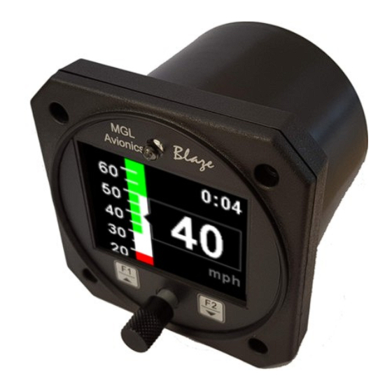
The ASI-5 is a 3 1/8" sunlight readable instrument that provides a wide range airspeed indication in both digital and
analog tape formats. Airspeed is based on the pressure generated by a pitot tube system and a static port is provided as
well for use by high speed aircraft. In addition, the ASI-5 provides a flight timer since takeoff and records the maximum
airspeed reached.
Airspeed can be indicated in statute miles per hour (mph), kilometers per hour (km/h) or nautical miles per hour (kts). The
analog airspeed tape can be scaled according to the aircraft's flying speed range and ranges for Vs0, Vs1, Vfe, Vno and
Vne can be set. The ASI-5 also provides a programmable Vs and Vne airspeed alarm output. ASI sensitivity can be
calibrated by the user to cater for errors caused by pitot tube placement.
The ASI-5 instrument measures airspeed from 16mph to 250mph and is well suited to slower aircraft due to very good
sensitivity and linearity at low air speeds.
1 Features
•
Large 2.6" high resolution 320x240, IPS (fully viewable in all directions), sunlight readable color LCD
display
•
Measures airspeed from 16mph to 250mph and is well suited to slow aircraft due to very good sensitivity
and linearity at low air speeds
•
Includes a flight timer since takeoff
•
Airspeed units can be set to miles per hour (mph), kilometer per hour (km/h) or nautical miles per hour
(kts)
•
Analog tape with programmable ranges for Vs0, Vs1, Vfe, Vno and Vne
•
Contains a programmable Vs and Vne airspeed alarm output
•
Records maximum airspeed reached in permanent memory
•
Standard 3 1/8" aircraft enclosure (can be front or rear mounted)
•
The LED backlight can automatically adjust to the ambient light, or it can be manually adjusted in the
menu system
•
Rotary control plus 2 independent buttons for easy menu navigation and user input
•
Wide input supply voltage range of 8 to 30V DC with built in voltage reversal and over voltage protection
for harsh electrical environments
•
1 year limited warranty
Blaze ASI-5
Airspeed Indicator (ASI)
Operating Manual – English 1.00
Advertisement
Table of Contents

Related Manuals for MGL Avionics Blaze ASI-5


Summary of Contents for MGL Avionics Blaze ASI-5
- Page 1 Blaze ASI-5 Airspeed Indicator (ASI) Operating Manual – English 1.00 Introduction The ASI-5 is a 3 1/8” sunlight readable instrument that provides a wide range airspeed indication in both digital and analog tape formats. Airspeed is based on the pressure generated by a pitot tube system and a static port is provided as well for use by high speed aircraft.
-
Page 2: Main Display
Blaze ASI-5 Operating Manual Page 2 2 Layout Ambient light sensor 3 1/8” enclosure. Can be front or rear mounted Sunlight readable color graphic display: The backlight can automatically adjust to the ambient light or it can be manually adjusted in the menu system... - Page 3 Blaze ASI-5 Operating Manual Page 3 3.1 Maximum Airspeed display This display can be accessed by rotating the rotary control during the normal display mode. Press the F1/Up button when the max values display is showing to reset the maximum values to the current airspeed.
-
Page 4: Exiting The Menu System
Blaze ASI-5 Operating Manual Page 4 4 Menu System Press the rotary control button during the normal display mode to enter the menu system. Use the rotary control to navigate through the menu system. 4.1 Exiting the menu system Press the F1/Up button to exit the menu system when the “EXIT” soft key is shown. All changes made during navigation of the menu system will be saved in non-volatile memory upon exiting. - Page 5 Blaze ASI-5 Operating Manual Page 5 Zero ASI Sensor: This setup allows your instrument to measure the zero airspeed reading of the airspeed sensor and set a calibration value internally for this. This is equivalent to some mechanical airspeed indicators that have an adjustment to set the needle to zero when the aircraft is not moving.
-
Page 6: Timers Setup
Blaze ASI-5 Operating Manual Page 6 Cal: During the factory calibration a factor has been determined and entered here that will give you accurate airspeed, provided your pitot tube is not influenced by pressure effects caused by airflow around your airframe. The calibration is displayed in % of the reading, you can increase or decrease the reading if required to help cancel out under or over reading of the airspeed indicator on your aircraft. -
Page 7: Security Setup
Blaze ASI-5 Operating Manual Page 7 4.4 MISC Setup (Miscellaneous Setup) Backlight: Select manual or automatic backlight control. Use the rotary control in manual mode to adjust the backlight brightness. Allow 3 seconds for the display to adjust to the ambient lighting conditions when using the automatic backlight mode. -
Page 8: Adc Values
Blaze ASI-5 Operating Manual Page 8 Default Settings: Select this menu option to reset all the settings to factory defaults. 4.5 ADC Values This menu displays the ADC value that have been read from the pressure sensor. 5 Loading factory default settings Press and hold the F1/Up button and rotary control during power up to load the pre- programmed factory default settings. -
Page 9: Error Messages
Blaze ASI-5 Operating Manual Page 9 6 Error Messages Unit settings CRC error. Load default settings to restore to factory defaults. If the error message still persists then it could possibly be a non-volatile memory failure in which case the instrument will then have to be returned to the factory. -
Page 10: Specifications
Blaze ASI-5 Operating Manual Page 10 7 Specifications Operating Temperature Range -10ºC to 60ºC (14ºF to 140ºF) Storage Temperature Range -20ºC to 80ºC (-4ºF to 176ºF) Humidity <85% non-condensing 8 to 30Vdc SMPS (switch mode power supply) with built in 33V over... -
Page 11: Installation
Blaze ASI-5 Operating Manual Page 11 11 Installation Connect a pitot tube to the “pressure port” and if required connect the static port. Most small aircraft such as ultralights or microlights do not require a connection to a static port. In these cases, simply leave the static port open. Ensure however that the static port does not receive pressurized air due to the forward movement of the aircraft. -
Page 12: Cable Connections
Blaze ASI-5 Operating Manual Page 12 11.2 Pressure Port Dimensions Inches Millimeters 0.248 0.278 6.30 7.06 0.420 0.440 10.67 11.18 0.182 0.194 4.62 4.93 0.310 0.330 7.87 8.38 11.3 Cable connections Main connector (D15HD connector: Unit Female, Cable Male) D15 Pin... - Page 13 IMPORTANT NOTICE: You must make your own determination if the products sold by MGL Avionics are safe and effective for your intended applications. MGL Avionics makes no representations or warranties as to either the suitability of any of the products we sell as to your particular application or the compatibility of any of the products we sell with other products you may buy from us or anywhere else, and we disclaim any warranties or representations that may otherwise arise by law.
Need help?
Do you have a question about the Blaze ASI-5 and is the answer not in the manual?
Questions and answers