Table of Contents
Advertisement
Quick Links
Introduction
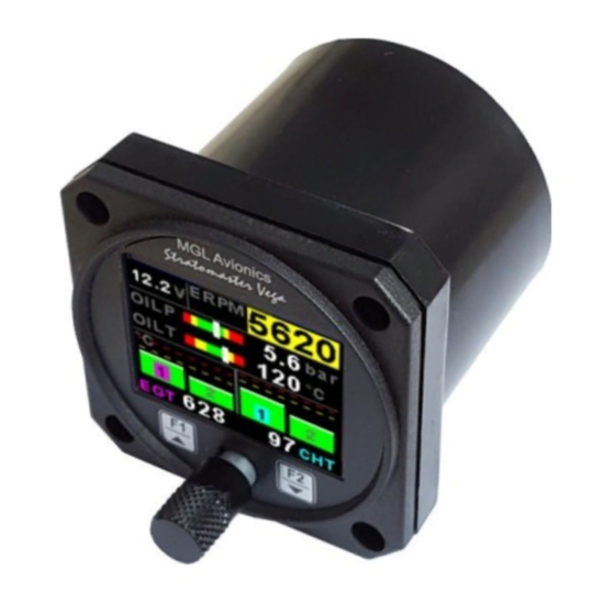
The Vega EMS-1 is a 2 1/4" (57mm) universal engine monitor color display instrument. The EMS-1 contains all the
necessary functionality to replace several engine monitoring instruments.
All information is displayed in an easy to read format on a high resolution wide viewing angle 1.8" 1000cd/m2 sunlight
readable color display.
The EMS-1 light weight, small size and high level of functionality makes it an excellent choice for all types of engines. The
EMS-2 can also interface directly to UL Power engines via the RS232 port.
The EMS-1 can also be interfaced via the CAN bus to an optional external RDAC unit (Remote Data Acquisition
Computer). This allows for easier installation as the RDAC unit is normally mounted in the engine compartment.
Vega EMS-1
Universal Engine Monitoring System
Operating Manual – English 1.09
Advertisement
Table of Contents

Related Manuals for MGL Avionics Vega EMS-1


Summary of Contents for MGL Avionics Vega EMS-1
- Page 1 Operating Manual – English 1.09 Introduction The Vega EMS-1 is a 2 1/4” (57mm) universal engine monitor color display instrument. The EMS-1 contains all the necessary functionality to replace several engine monitoring instruments. All information is displayed in an easy to read format on a high resolution wide viewing angle 1.8” 1000cd/m2 sunlight readable color display.
-
Page 2: Fuel Level
Analog channels are universal and can be configured to measure Pressure, Temperature or Current • Current measurement requires a MGL Avionics Closed Loop Current Sensor • Pressure can be measured using standard automotive resistive senders (e.g. VDO 2, 5 and 10Bar), Rotax 4-20mA senders as well as voltage output pressure senders (e.g. -
Page 3: Manifold Pressure
Displays warning messages from the UL Power ECU Rotax 912iS • The EMS-1 can connect to the Rotax 912iS ECU directly or by using the MGL Avionics RDAC CAN 912iS • Displays engine information from the Rotax 912iS ECU •... -
Page 4: Main Displays
Vega EMS-1 Operating Manual Page 4 2 Layout 2 1/4” enclosure. Can be front or rear mounted Sunlight readable color graphic display: Backlight can be adjusted in the menu system F2 / Down Button: Menu System: Softkey button F1 / Up Button:... - Page 5 2 second intervals. EGT/CHT display section The Vega EMS-1 supports up to 4 thermocouples (using the internal electronics) and up to 12 thermocouples (using the optional external RDAC). The EGT/CHT section will automatically try and maximize the display area according to the number of EGTs/CHTs selected.
- Page 6 HOBBS: The Vega EMS-1 contains a password protected Hobbs timer. The Hobbs time can be set to the current known engine time in the “TIMERS SETUP” menu. The Hobbs timer will only increment when the RPM is greater then the “HOBBS RPM”.
- Page 7 Vega EMS-1 Operating Manual Page 7 3.2 EGT/CHT Trend Graph display This display can be accessed by rotating the rotary control during the normal display mode. The trend graph displays the last 160 seconds of EGT/CHT temperature readings. 3.3 Maximum Values display This display can be accessed by rotating the rotary control during the normal display mode.
- Page 8 Vega EMS-1 Operating Manual Page 8 3.5 Engine cruise mode Once in the cruise, press the F2/Down button to enable the Cruise Mode. "CRUISE" label is displayed at the top of the main display to clearly differentiate it from the normal operating mode. All EGT and CHT readings are...
-
Page 9: Menu System
Vega EMS-1 Operating Manual Page 9 4 Menu System Press the rotary control button during the normal display mode to enter the menu system. Use the rotary control to navigate through the menu system. -
Page 10: Exiting The Menu System
Vega EMS-1 Operating Manual Page 10 4.1 Exiting the menu system Press the F1/Up button to exit the menu system when the “EXIT” soft key is shown. All changes made during navigation of the menu system will be saved in non-volatile memory upon exiting. The instrument will not save any changes if you remove power before exiting the menu system. - Page 11 Vega EMS-1 Operating Manual Page 11 4.3 RPM 1 Setup menu option Display: Select if you want the RPM to be displayed in “RPM”, “PERCENT” or “OFF”. RPM 100%: Select the maximum value that you want the RPM to correlate to 100%. This is only shown if “Percent” is selected for display.
- Page 12 Vega EMS-1 Operating Manual Page 12 Low Alarm: This enables or disables the RPM low alarm. Low Alarm: Enter the RPM threshold for when the low alarm must be activated. Any RPM value below this value will activate the alarm.
- Page 13 Vega EMS-1 Operating Manual Page 13 4.4 RPM 2 / Fuel Flow Setup menu option The RPM-2 input can be used for RPM or fuel flow. If RPM is selected for “MODE” Mode: Select if you want to display “RPM2” or “FUEL FLOW” or “OFF”...
- Page 14 Vega EMS-1 Operating Manual Page 14 High Caution: Enter the RPM value for the high caution. This is the lower value of the upper yellow band. Low Caution: Enter the RPM value for the low caution. This is the upper value of the lower yellow band.
- Page 15 The K-Factor is the number of pulses generated by the fuel flow sender for one Litre of fuel. The dual range fuel flow sender supplied by MGL Avionics has a K-Factor of 7000 in the low flow mode (jet installed) and 1330 for the high flow mode (no jet installed).
- Page 16 Vega EMS-1 Operating Manual Page 16 4.5 EGT / CHT Setup (Thermocouple Setup) EGT / CHT Channels: Select the number of EGT or CHT channels you want to use. Choices are from 1 to 4 (1 to 12 if using the optional RDAC) .
- Page 17 Vega EMS-1 Operating Manual Page 17 High Caution: Enter the temperature value for the high caution. Probe: Select if you are using a K-type, J-type or E-type thermocouple probe for this channel. All probes supplied by MGL Avionics are K-Type. J-types are sometimes used with American made CHT probes. All EGT probes are K-type. E-type probes are seldom used.
-
Page 18: Pressure Setup
Vega EMS-1 Operating Manual Page 18 4.6 Analog CH1 to CH4 Setup The 4 analog channels are universal analog input channels that can be used for pressure, temperature or current. Only “CHANNEL 1” Setup is shown below, follow the same steps for Channel 2, 3 & 4 4.6.1 Pressure Setup... - Page 19 Vega EMS-1 Operating Manual Page 19 If the “VOLTAGE” pressure sender is selected Sender: Select the type of voltage sender you are using. Select “UMA” for UMA senders, "0.5-4.5V" for voltage senders, or “USER” for a custom voltage sender. Model: For UMA senders select the UMA model number.
-
Page 20: Temperature Setup
Vega EMS-1 Operating Manual Page 20 Low Caution: Enter the pressure value for the low caution. This is the upper value of the lower yellow band. Low Alarm: This enables or disables the pressure low alarm. Low Alarm: Enter the pressure threshold for when the low alarm must be activated. Any pressure below this value will activate the alarm. - Page 21 Vega EMS-1 Operating Manual Page 21 If the sender type is set to “LM335" LM335: If the sender type is set to LM335, then use this menu option to calibrate your LM335 precision temperature sender. If recalibration is required then adjust the value until the temperature matches the reference ambient temperature. Please note that the LM335 can only be calibrated in degrees Celsius irrespective if the EMS-1 is setup to display temperature in Fahrenheit.
- Page 22 5. Verify the above calibration by checking the temperature, pressure or current display versus the actual applied sender stimulus. 4.6.4 Current Setup (requires a MGL Avionics Closed Loop Current Sensor) Mode: Select the function for the analog channel. Options are “PRESSURE”, “TEMP”, “CURRENT” or “OFF”.
-
Page 23: Zero Sensor
Adjust the gain factor until the current is reading correctly. It will be best if a multimeter can be inserted in series with the current supplying conductor and the gain calibration adjusted until the EMS-1 matches that of the multimeter. Please see the MGL Avionics Closed Loop Current Sensor documentation for more information. Data: Select the data source of the current signal. -
Page 24: Low Alarm
Vega EMS-1 Operating Manual Page 24 Mode: Select the function for the analog channel. Options are “PRESSURE”, “TEMP”, “CURRENT”, “FUEL LEVEL” or “OFF”. Label: Enter a label to suit your fuel level channel so you can identify it easily. Unit: Select whether you want the fuel level to be displayed in Litres or in Gallons. - Page 25 Vega EMS-1 Operating Manual Page 25 4.6.5.1 Calibrating the fuel level senders The fuel level sender needs to be calibrated before it can be used with this system. The calibration allows the system to learn the shape of your tank as well as any errors your fuel level sender or installation has.
- Page 26 Vega EMS-1 Operating Manual Page 26 Adjusting calibration points manually You may want to set individual calibration points manually. For example you may find that your fuel level is over reading at a specific fuel level. Correcting the tank level reading for this area can be simply done by adjusting the calibration point.
- Page 27 Vega EMS-1 Operating Manual Page 27 4.7 Volts Setup Display: Select is you want the Volts to be displayed as a numeric only value at the top of the display or if you want to have it displayed as a bargraph. Select “OFF” to disable the volts display.
- Page 28 Vega EMS-1 Operating Manual Page 28 Low Alarm: This enables or disables the volts low alarm. Low Alarm: Enter the voltage threshold for when the low alarm must be activated. Any voltage below this value will activate the alarm. Cal:...
-
Page 29: High Alarm
Vega EMS-1 Operating Manual Page 29 4.8 MAP Setup (Manifold Setup) Display: Select is you want the MAP to be displayed as a numeric only value at the top of the display or if you want to have it displayed as a bargraph. Select “OFF” to disable the MAP display. - Page 30 Vega EMS-1 Operating Manual Page 30 Low Caution: Enter the pressure value for the low caution. This is the upper value of the lower yellow band. Low Alarm: This enables or disables the manifold pressure low alarm. Low Alarm: Enter the pressure threshold for when the low alarm must be activated. Any pressure below this value will activate the alarm.
- Page 31 Vega EMS-1 Operating Manual Page 31 4.9 Current Setup (MGL Avionics Closed Loop Current Sensor and RDAC required) Display: Select to enable or disable the RDAC current display. Label: Enter a label to easily identify your Current reading. High Alarm: This enables or disables the current high alarm.
- Page 32 Adjust the gain factor until the current is reading correctly. It will be best if a multimeter can be inserted in series with the current supplying conductor and the gain calibration adjusted until the EMS-1 matches that of the multimeter. Please see the MGL Avionics Closed Loop Current Sensor documentation for more information. RDAC Address:...
-
Page 33: Timers Setup
Vega EMS-1 Operating Manual Page 33 4.10 Timers Setup Set UTC Time: This function is used to set the internal real time clock. The time to be entered must be UTC in order for the system to operate correctly. Do not enter local time (unless it is the same as UTC). - Page 34 Vega EMS-1 Operating Manual Page 34 HOBBS CODE: This menu option allows you to change the Hobbs access code. You will first be prompted to enter the current code followed by entering in a new code followed by re-entering the new code. If the new code and the re-entered code is the same, then the Hobbs access code will be changed.
- Page 35 The Rotax 912iS ECU can be connected to the EMS-1 either by direct connection or by using the MGL Avionics RDAC CAN 912iS. Connect: Select if the Rotax 912iS ECU is connected to the EMS-1 by direct connection or by using the MGL Avionics RDAC CAN 912iS. Lane: (Direct connection only)
- Page 36 Vega EMS-1 Operating Manual Page 36 The Rotax 912iS ECU Oil temperature is mapped to the EMS-1 Analog CH 1 (renamed to Oil Temp Setup), Rotax 912iS ECU Oil Pressure to the EMS-1 Analog CH 2 (renamed to Oil Press Setup) and the Rotax 912iS ECU Coolant temperature to the EMS-1 Analog CH 3 (renamed to Coolant Temp Setup).
- Page 37 RDAC CAN Rotax 912iS Connection The EMS-1 can also be connected to the Rotax 912iS ECU via the MGL Avionics RDAC CAN. Please see the RDAC CAN 912iS documentation for installation and usage. If using the RDAC CAN Rotax 912iS then the EMS-1 needs to be setup as below.
- Page 38 Vega EMS-1 Operating Manual Page 38 Rotax 912iS recommended settings: Engine RPM: 0 to 1500 RPM: Red 1500 to 1800 RPM: Yellow 1800 to 5500 RPM: Green >5800 RPM: Red MAP: 0 to 200 mBar: Yellow 200 to 1100 mBar: Green 1100 to 1150 mBar: Yellow >1150 mBar: Red...
- Page 39 Vega EMS-1 Operating Manual Page 39 4.11.2 UL Power ECU Connect the UL Power Engine to the EMS-1 RS232 port using the UL Power cable E080305 (RS232-EFIS cable). ECU/AIR TEMP (ULPower ECU only): Select whether you want the temperature to be displayed in degrees Celcius (ºC) or in degrees Fahrenheit (ºF).
- Page 40 Oil Temperature to the EMS-1 Analog CH 2 (renamed to Oil Temp Setup) and the ULPower ECU Fuel Pressure to the EMS-1 Analog CH3 (renamed to Fuel Press Setup). These channels need to be setup accordingly. The MGL Avionics RDAC can be used to measure CHT, EGT and MAP. The EMS-1 also supports the ULPower Aux box ULPower recommended settings: Oil Pressure: max 8 bar (115psi) - normal 2 to 5 bar (30 –...
-
Page 41: Protocol Format
Vega EMS-1 Operating Manual Page 41 4.12 COMM Setup (Communication Setup) Serial Out: Select “ON” to enable the RS232 serial output. Unit Address: Enter the EMS-1 unit address. Baud Rate: Select the desired baud rate of the serial output. The transmission format is set to 8 data bits, No parity, 1 stop bit. The baud rate can be changed in the Communication Menu. - Page 42 Vega EMS-1 Operating Manual Page 42 4.12.2 Data payload Message type=1 Data Length=69 bytes Output Rate=1Hz Unused channels will read 0 Local Time: Unsigned Long (32 bit), Time is seconds since 1 January 1970 Hobbs Hours: Unsigned Int (16 bits), Hobbs hours...
- Page 43 Vega EMS-1 Operating Manual Page 43 Temperature in Degrees C Current in 0.1A Fuel Level in Liters Manifold Pressure: Signed Int (16 bits), Manifold pressure in mBar Current: Signed Int (16 bits), Current in 0.1A CJC: Signed Int (16 bit), Cold junction temperature in Degrees Celsius...
-
Page 44: Security Setup
Vega EMS-1 Operating Manual Page 44 4.13 MISC Setup (Miscellaneous Setup) Backlight: Select this menu option to adjust the backlight brightness. Security Setup: Select this menu option if you want to password protect the menu system. Information: This menu option displays information about the unit. -
Page 45: Adc Values
Vega EMS-1 Operating Manual Page 45 Default Settings: Select this menu option to reset all the settings to factory defaults. 4.14 ADC Values This menu displays the ADC values of the various sensors. 5 Loading factory default settings Press and hold the F1/Up button and rotary control during power up to load the pre- programmed factory default settings. -
Page 46: Error Messages
Vega EMS-1 Operating Manual Page 46 6 Error Messages Unit settings CRC error. Load default settings to restore to factory defaults. If the error message still persists then it could possibly be a non-volatile memory failure in which case the instrument will then have to be returned to the factory. -
Page 47: Specifications
+/- 5 degrees typical over full temperature range, subject to quality of probe Measurement accuracy used. We recommend MGL Avionics EGT and CHT probes Inputs Differential, can use grounded and isolated probes Common mode voltage range... - Page 48 Vega EMS-1 Operating Manual Page 48 Pressure Sender Input VDO Resistive Sender: The EMS-1 supports the VDO 2, 5 and 10 Bar senders. VDO pressure senders used to measure fuel pressure require the fuel isolation kit available from VDO. Rotax 4-20mA Sender: The EMS-1 supports the 4-20mA pressure sender as used in Rotax 912/914 engines.
-
Page 49: Firmware Upgrading
Vega EMS-1 Operating Manual Page 49 Current Sensor Current Sensors MGL Avionics Closed Loop Current Sensor Volts Voltage measurement range Up to 32Vdc Voltage resolution 0.1V OAT Probe OAT Temperature Sender type Semiconductor LM335 (STMicroelectronics) Internal battery type CR2032 8 Operating the alarms The alarm output can be used to switch an external alarm indicator. -
Page 50: Installation
Vega EMS-1 Operating Manual Page 50 11 Installation 11.1 Connection Diagram The use of an external 1A fuse is recommended. Connect the supply terminals to your aircrafts power supply. The EMS-1 can be used on both 12V and 24V without the use of any pre-regulators. Ensure that the supply voltage will not drop... - Page 51 This often breaks after the spark plug has been changed a few times. Choose a probe that is suitably reinforced at this point for a long and trouble free life. EGT and CHT probes supplied by MGL Avionics are of the highest quality. We recommend that you consider using our probes if at all possible.
- Page 52 Vega EMS-1 Operating Manual Page 52 11.2.1 Extending the leads of thermocouple probes Thermocouple leads as used with the EGT and CHT probes can be extended either with ordinary copper cable or with special K-Type extension cable. The choice of either depends on your desired accuracy. If it is possible in your installation to ensure that both ends of a copper extension cable will be at the same temperature (or very close), then it is quite possible to use the copper cable.
- Page 53 Vega EMS-1 Operating Manual Page 53 11.3.2 RPM 1 Input Dipswitch settings Setting dipswitch 4 to the “ON” position (default) enables a high frequency filter in the RPM 1 signal path. Some installations (direct coupling to a Magneto device for example) will require this to be switched “OFF”.
- Page 54 Vega EMS-1 Operating Manual Page 54 11.3.4 Connecting the EMS-1 to automotive engines Conventional contact breaker ignition system Connect rev counter input Use the tacho line of EMS-1 to this line. if your system has Ensure you have a such a signal connection from the EMS-1 ground to the engine block.
-
Page 55: Hall-Effect Sensor
Vega EMS-1 Operating Manual Page 55 11.3.5 Various other pickup / sensor installation possibilities Hall-effect sensor Typical hall effect sensor installation detects the passing of a magnet suitably fixed to prop flanges or shafts. Gear tooth sensor The gear tooth sensor is a popular pickup used on the pre-rotation gear of a gyro plane (rotor speed indication). - Page 56 Vega EMS-1 Operating Manual Page 56 11.4 Temperature senders VDO Resistive senders: The EMS-1 supports the VDO 120ºC and 150ºC thermistor automotive senders. The internal pull up resistor dip switch for the resistive temperature sender input must be in the “ON” position.
- Page 57 Vega EMS-1 Operating Manual Page 57 11.5.1 UMA Voltage output pressure sender Pinout: White/Orange: +12Vdc White: Signal White/Blue: Ground Shield: Ground 11.5.2 ROTAX 912/914 4-20mA Pressure sender The sensor cable is approximately 3m long and has 3 leads. The black lead is not to be connected and has no function.
- Page 58 Vega EMS-1 Operating Manual Page 58 11.6 Fuel flow sender installation The fuel flow sender allows the EMS-1 to provide instantaneous readout of hourly fuel usage. Please note that the installation of the fuel Flow sender should be done in such a fashion that dirt or debris from the fuel tank cannot lodge inside the flow sender.
- Page 59 Using other Flow Senders It is quite possible to use flow senders other than the MGL Avionics fuel flow sender. In this case ensure that the sender outputs a 5V TTL square wave or a similar signal. The EMS-1 interface electronics will adapt to a variety of different voltages and pulse shapes as it contains a Schmitt-trigger input stage.
-
Page 60: Fuel Level Senders
Vega EMS-1 Operating Manual Page 60 11.7 Fuel level senders The EMS-1 permits the connection of standard automotive fuel level senders. These senders can be obtained at automotive spares outlets at reasonable cost. When you choose a float level sender, ensure that you select a model that is sturdy and promises reliable and long lifetime. - Page 61 Vega EMS-1 Operating Manual Page 61 11.8 Analog Channels Dipswitch settings Use a small screwdriver to change the switch direction. Dipswitch Function Analog Input Channel 1 Pull up resistor (On=Enable, OFF=Disable) Analog Input Channel 2 Pull up resistor (On=Enable, OFF=Disable)
- Page 62 Page 62 11.11 Closed Loop Current Sensor The MGL Avionics magnetic closed loop current sensor provides a 0.5V to 4.5Vdc output voltage which is proportional to a 50A bi-directional input current. Advantages of closed loop current sensors over conventional current measurements techniques is that they provide the highest accuracy, are ideal for noisy electrical environments and they provide complete electrical isolation f rom the current carrying conductor.
- Page 63 Vega EMS-1 Operating Manual Page 63 11.13 Senders that are grounded in the engine block Single wire senders require that their mounting arrangement (thread) has a very good electrical contact with the engine block. Avoid the use of any sealant or tapes as these may cause a bad electrical connection. Further to this it is very important that the engine block has a good electrical connection to the negative supply terminal of the EMS-1.
-
Page 64: Cable Connections
+5Vdc Power out Sensor power White Alarm Output (Open collector) Thermocouple (EGT/CHT) connector (D9 connector: Unit Male, Cable Female) In case of MGL Avionics K-Type probes + = Yellow probe lead, - = Red probe lead D9 Female Pin Color Function... - Page 65 Vega EMS-1 Operating Manual Page 65 12 Dimensions...
-
Page 66: Warranty
IMPORTANT NOTICE: You must make your own determination if the products sold by MGL Avionics are safe and effective for your intended applications. MGL Avionics makes no representations or warranties as to either the suitability of any of the products we sell as to your particular application or the compatibility of any of the products we sell with other products you may buy from us or anywhere else, and we disclaim any warranties or representations that may otherwise arise by law. - Page 67 Vega EMS-1 Operating Manual Page 67 Other instruments in the Stratomaster Vega series AHRS-1 Artificial Horizon and Magnetic Compass Indicator AHRS-3 Self contained Artificial Horizon and Magnetic Compass Indicator ALT-5 Altimeter and Vertical Speed Indicator (VSI) ASI-4 Airspeed Indicator (ASI)
Need help?
Do you have a question about the Vega EMS-1 and is the answer not in the manual?
Questions and answers