Table of Contents
Advertisement
Quick Links
Introduction
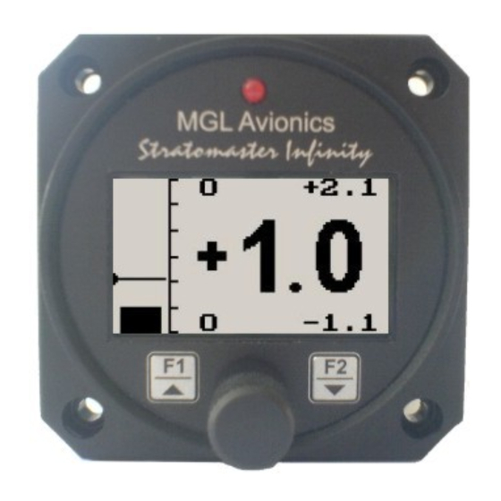
The GF-1 is a 2 1/4" G-force meter capable of measuring G-forces exerted in an aircraft up to +-10g. The forces acting on
the aircraft are easily seen on a large backlit graphic display both numerically and graphically. The GF-1 also has the
facility to record maximum G-forces obtained in permanent memory as well as a temporary memory to record G-forces
reached from the time of power up. It also features 2 independent cycle counters to capture the amount of times a preset
force has been exceeded. The GF-1 is able to measure G-forces even if the instrument is not mounted exactly on the
vertical axis of the aircraft.
1 Features
•
Typical, accurate range up to 20g (from -10g to +10g)
•
Records maximum measured forces in permanent memory (both positive and negative G-forces), with
password protected reset facility
•
Two independent cycle counters record the number of times a preset force has been exceeded
•
Temporary memory for maximum positive and negative G-forces encountered (typically during a flight)
•
Clear, large readable G-force numerical value (10G positive and negative)
•
Scalable graphic analog display of force acting on the aircraft
•
2 axis design of the instrument allows mounting in sloped panels (i.e. panel not exactly vertical)
•
Quick calibrations function for operation at temperature extremes using Earth's gravity
•
Bilingual support (English or French)
•
Standard 2 1/4" aircraft enclosure (can be front or rear mounted)
•
Rotary control plus 2 independent buttons for easy menu navigation and user input
•
An external alarm output as well as a red LED illuminates every time the aircraft exceeds a preset G-force
•
Large backlit graphic LCD with adjustable contrast
•
Wide input supply voltage range of 8 to 30V DC with built in voltage reversal and over voltage protection
for harsh electrical environments
•
Light weight design
•
1 year limited warranty
GF-1
+-10g Tilt Compensated dual range
aviation G-force meter
Operating Manual – English 1.05
Advertisement
Table of Contents

Summary of Contents for MGL Avionics GF-1
- Page 1 Introduction The GF-1 is a 2 1/4” G-force meter capable of measuring G-forces exerted in an aircraft up to +-10g. The forces acting on the aircraft are easily seen on a large backlit graphic display both numerically and graphically. The GF-1 also has the facility to record maximum G-forces obtained in permanent memory as well as a temporary memory to record G-forces reached from the time of power up.
-
Page 2: Main Display
GF-1 Operating Manual Page 2 2 GF-1 Layout LED Alarm: The red LED will illuminate if any of the G-force cycle counters have been exceeded Backlit Graphic LCD Display: Contrast and backlight can be adjusted in the menu system Harness:... -
Page 3: Menu System
This display can be accessed by turning the rotary control either clockwise or anti-clockwise. Pressing the F1 key will reset the permanent maximum values to the current G-force value. Pressing any other key will cause the GF-1 to return to the normal display mode. -
Page 4: Display Setup
4.1 Exit Menu Pressing the rotary control on this menu item will cause the GF-1 to exit the menu system. All changes made during navigation of the menu system will be saved in non-volatile memory on exiting the menu system. -
Page 5: Adc Values
GF-1 Operating Manual Page 5 Move the highlight over the “DONE” menu item and press the rotary button to return to the main menu Set the maximum G-force value that you would like the analog bar graph to display Set the positive G-force limit above which the cycle counter should increment... -
Page 6: Loading Factory Default Settings
You have now calibrated both the horizontal and vertical G-force using Earth’s gravity as the reference. 5 Loading Factory default settings Pressing and holding the F1 and F2 keys simultaneously on power up will cause the GF-1 to load pre-programmed factory default settings. The following screen will be displayed:... - Page 7 The unit should not be cleaned with any abrasive substances. The screen is very sensitive to certain cleaning materials and should only be cleaned using a clean damp cloth. Warning: The GF-1 is not waterproof. Serious damage could occur if the unit is exposed to water and/or spray jets.
-
Page 8: Installation
9.1 Connection Diagram The use of an external 1A fuse is recommended. Connect the supply terminals to your aircrafts power supply. The GF-1 can be used on both 12V and 24V without the use of any pre-regulators. Ensure that the supply voltage will not drop below 8V during operation as this may result in incorrect G-force readings. - Page 9 GF-1 Operating Manual Page 9 10 Warranty This product carries a warranty for a period of one year from date of purchase against faulty workmanship or defective materials, provided there is no evidence that the unit has been mishandled or misused. Warranty is limited to the replacement of faulty components and includes the cost of labour.


Need help?
Do you have a question about the GF-1 and is the answer not in the manual?
Questions and answers